Introduction
This page documents the work completed for Week 3 – Computer Controlled Cutting.
Here I will describe the machines used, the materials tested, and the workflow from design to cutting.
Assignments
Group Assignemnt
Group Assignment Link This week our assignment is:
- Vinyl Cutting
- Cut something on the vinyl cutter.
- Laser Cutting
- Design, laser cut, and document a parametric construction kit, accounting for the laser cutter kerf.
- Extra credit: design it to be assembled in multiple ways.
- Extra credit: include elements that are not flat.
- Extra credit: engrave as well as cut.
Vinyl Cutting
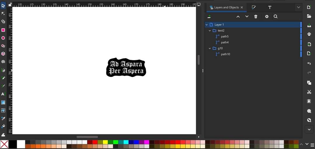
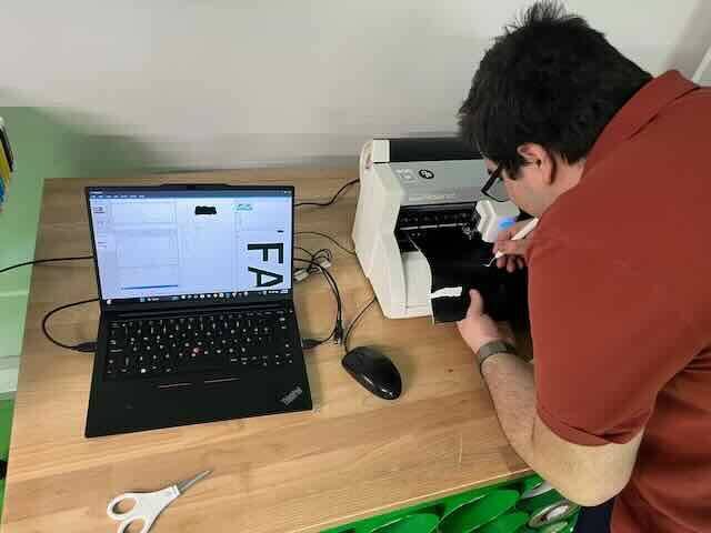
I designed a sticker for my laptop using Inkscape and cut it on the Roland GS2‑24.
I wanted to have a sticker of our FRC team’s motto, “Ad Astra per Aspera”, which is a Latin phrase meaning “to the stars through hardships” according to Wikipedia. I started by inserting the text and choosing a font. Then I used Object → Object to Path to convert the text into paths and duplicated it. On the duplicated text I applied Outset to create the background, then used Fill between paths to fill the gaps in the background, and finally used Union to merge everything into one path. I then used Simplify to make the curves smoother.
When the design was finished, I imported it into Illustrator to adjust the stroke color to the GS2‑24 preset cut‑contour colors so that, when I exported it as .eps and opened it in the GS2‑24 software, the machine would recognize where to cut. I also separated the two colors (white and black), since I needed to cut them on separate rolls with different vinyl colors. I started with the black background since it was a single piece and much easier to weed and apply to my computer.
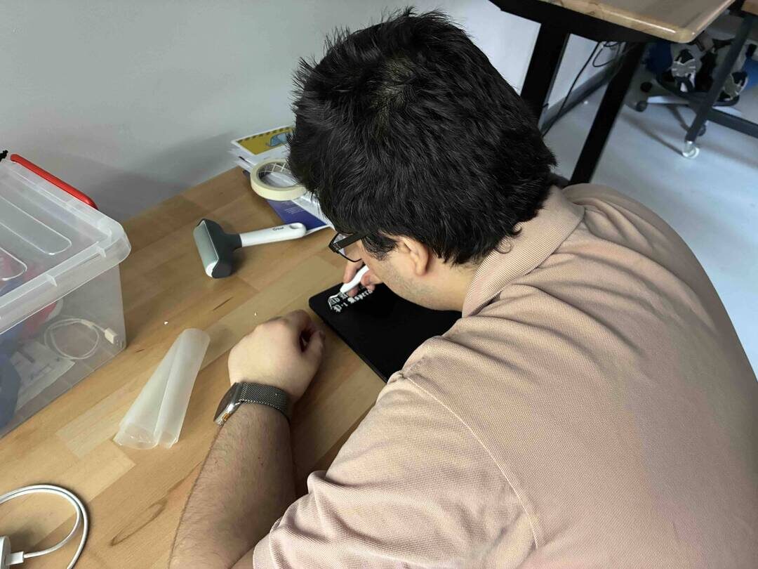
I used a needle tool to weed out the excess vinyl from the main roll.
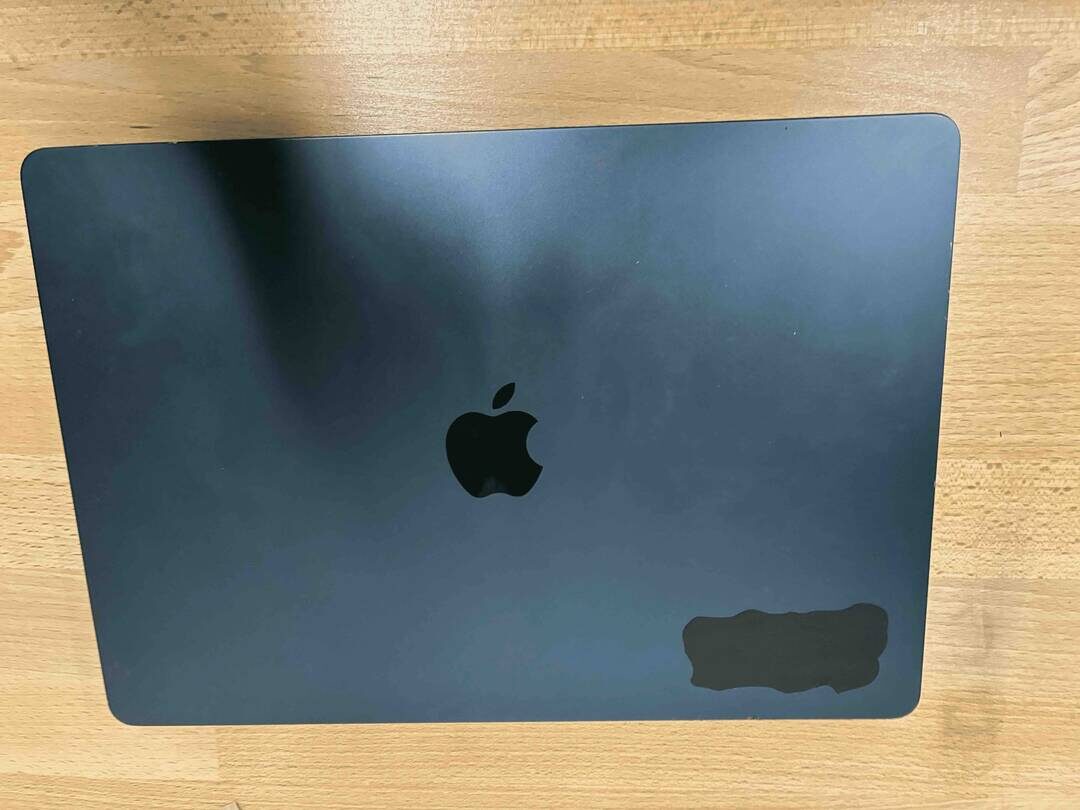
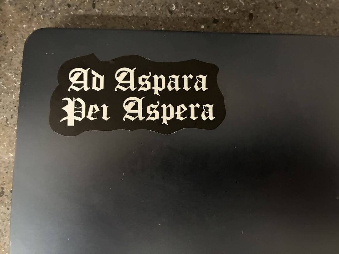
I then stuck the black vinyl on my computer by hand.
Next, I loaded the white vinyl roll on the GS2‑24 and cut the text. To transfer the letters, I used transfer tape, which is a slightly sticky tape that picks up the cut vinyl from the backing.
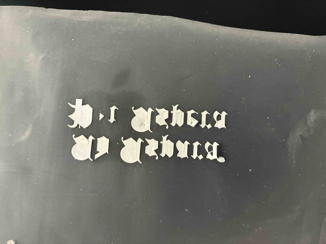
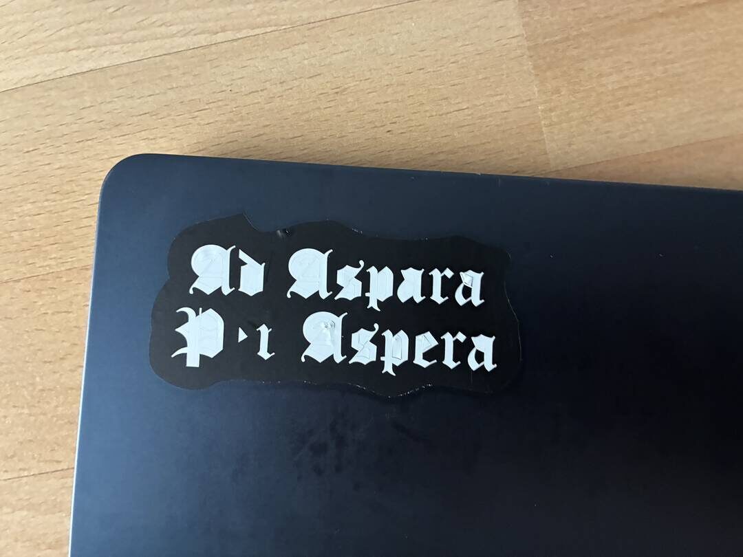
Then I transferred the white text onto the black background and used the needle tool again to weed the unwanted vinyl inside the letters. In retrospect, choosing a simpler font with less detail would have made this process much easier.
Laser Cutting
For the laser cutting assignment, I designed a parametric construction kit for a model satellite.
I started by designing the side panels of the satellite.
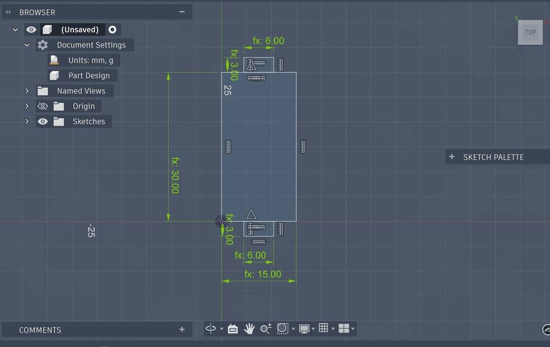
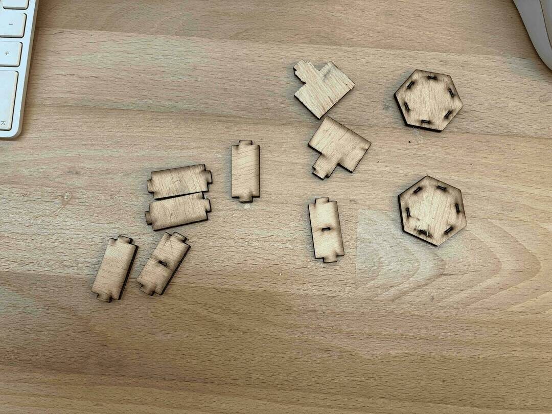
The side panel design is a simple rectangle with two smaller rectangles sticking out from the middle of the longer sides to act as joints for connecting to other parts. A key detail is that I made the height of the joint rectangles equal to the material thickness, so when they slot into other 3 mm‑thick parts they do not protrude.
Next, I designed the top and bottom panels of the satellite.
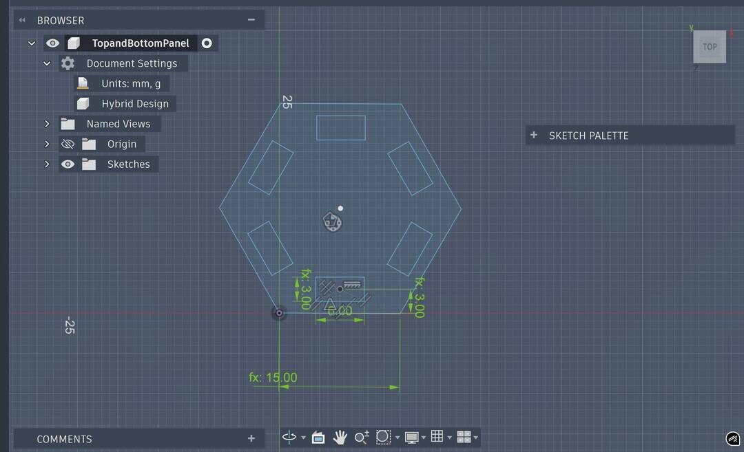
For these, I drew a hexagon and added rectangular slots inside it that serve as connection points for the side panels. Then I used a circular pattern tool around the hexagon’s center to duplicate this rectangle evenly around the shape.
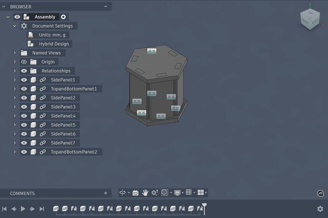
The initial assembly looked good, but I wanted it to look more like a satellite with solar panel wings, so I added those next.
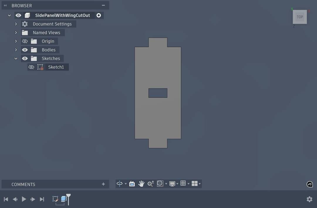
I designed a modified side panel with a cut‑out in the middle where the wing elements could attach.
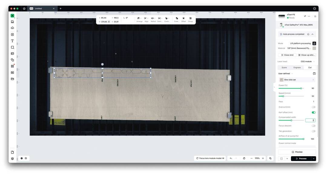
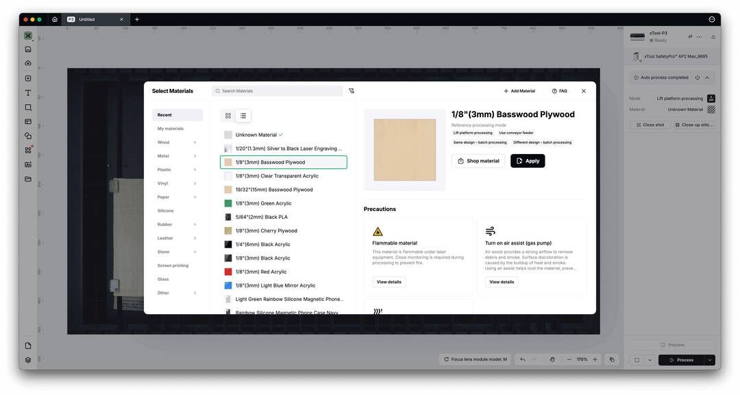
I cut the design from 3 mm plywood using the xTool P3 and its software, xTool Studio. I started from the material presets in xTool Studio and then adjusted the kerf using the kerf offset setting. At first, I entered a kerf offset of 1, assuming it would offset the cut inwards, but it worked the opposite way and made the joints too tight. Using that information, I adjusted the kerf offset again until the joints fit correctly.
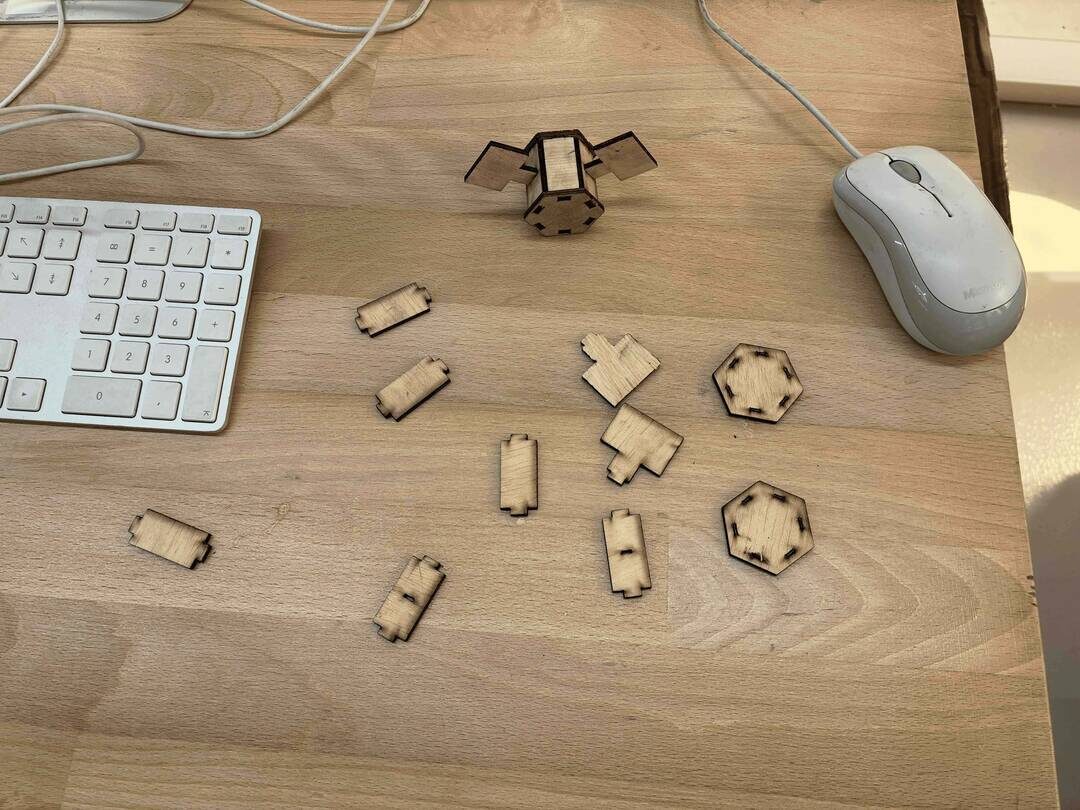
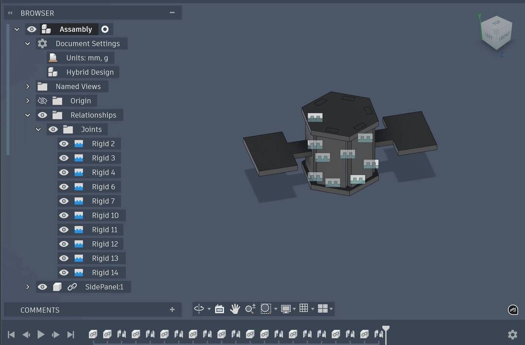
In the end, I obtained a parametric hexagonal satellite whose wing positions and overall dimensions can be adjusted by changing the parameters in the design. The parts press‑fit together thanks to the kerf compensation, and the model can be assembled in different configurations.