Assignment
- model (raster, vector, 2D, 3D, render, animate, simulate, …) a possible final project
CAD (Fusion 360)
I will CAD the 3D robot chassis for my robot education kit.
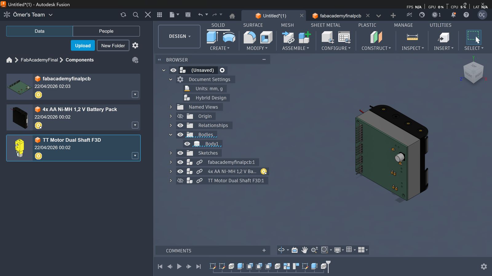
I started by inserting my PCB STEP file and battery pack, connected them with a 15 mm thick square, and cut the mounting holes through.
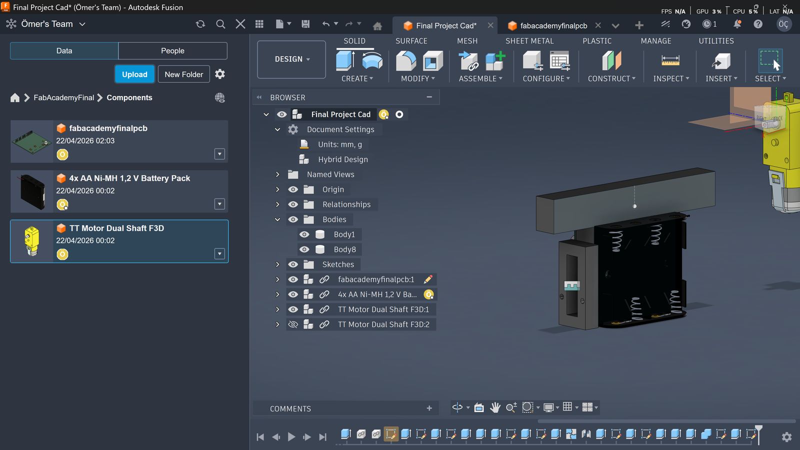
Then I designed a mounting structure for the yellow motor by referencing its own geometry. It is a rectangle with an internal cutout for the unused shaft and two matching mounting holes. I designed this as a separate body so I could mirror it.
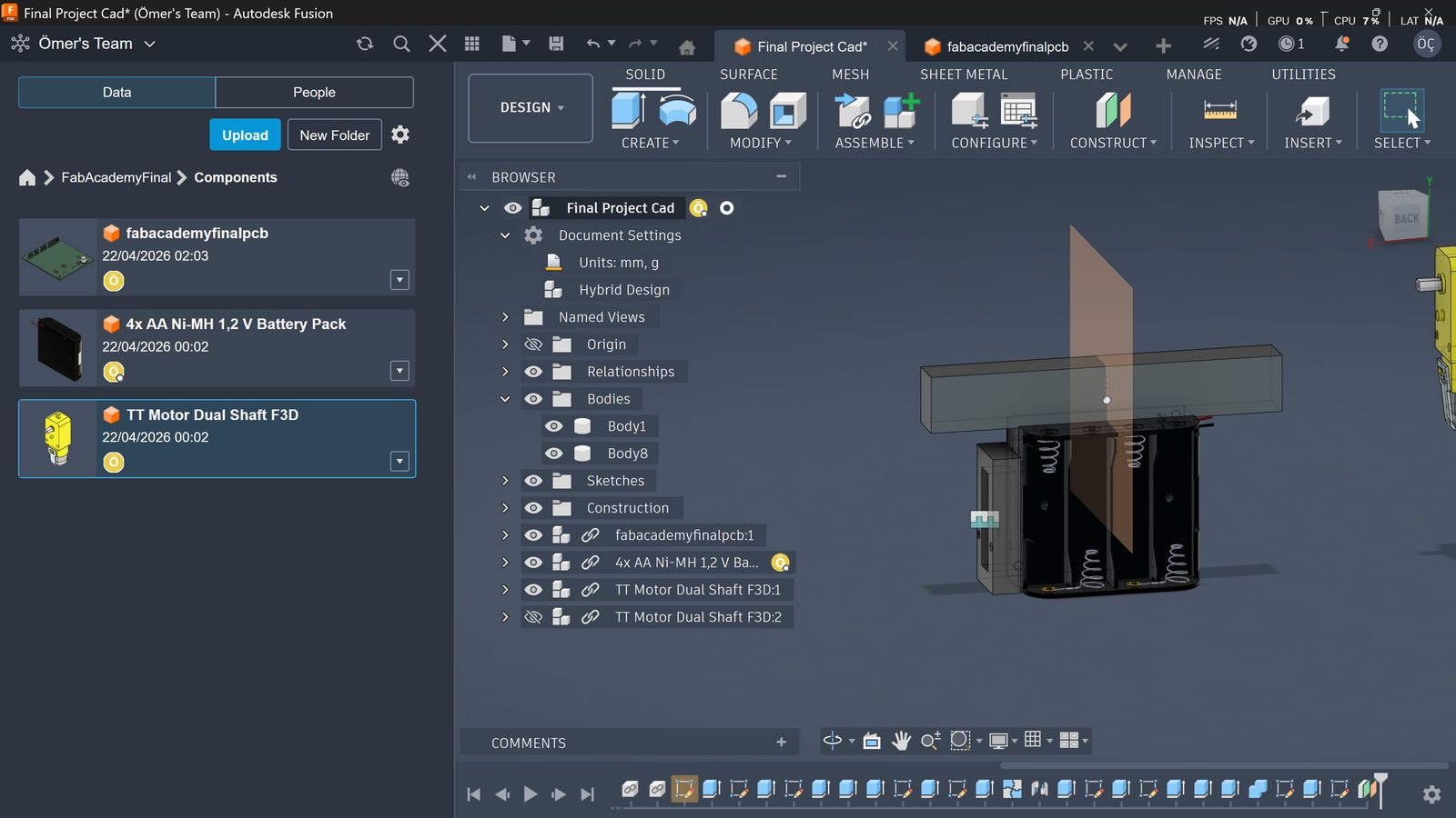
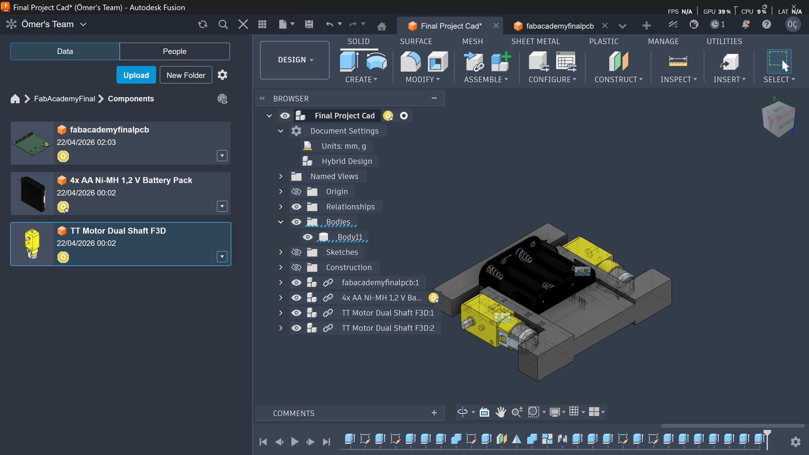
I then added a construction plane in the middle of the part so I could use that as reference for mirroring.
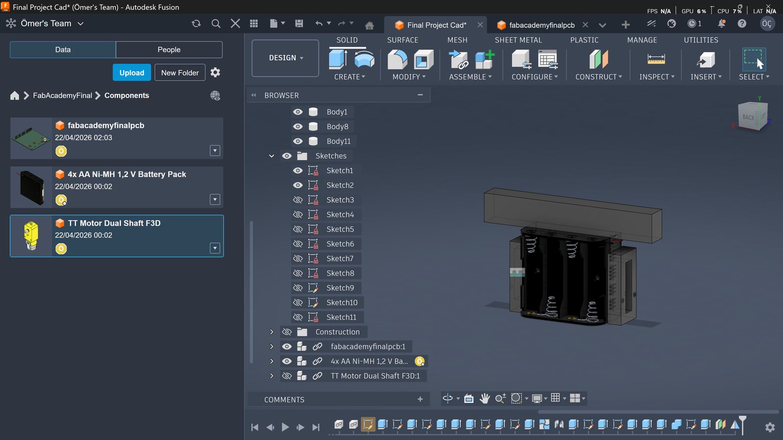
Then I mirrored the body as planned and used the combine function to combine the three bodies into one.
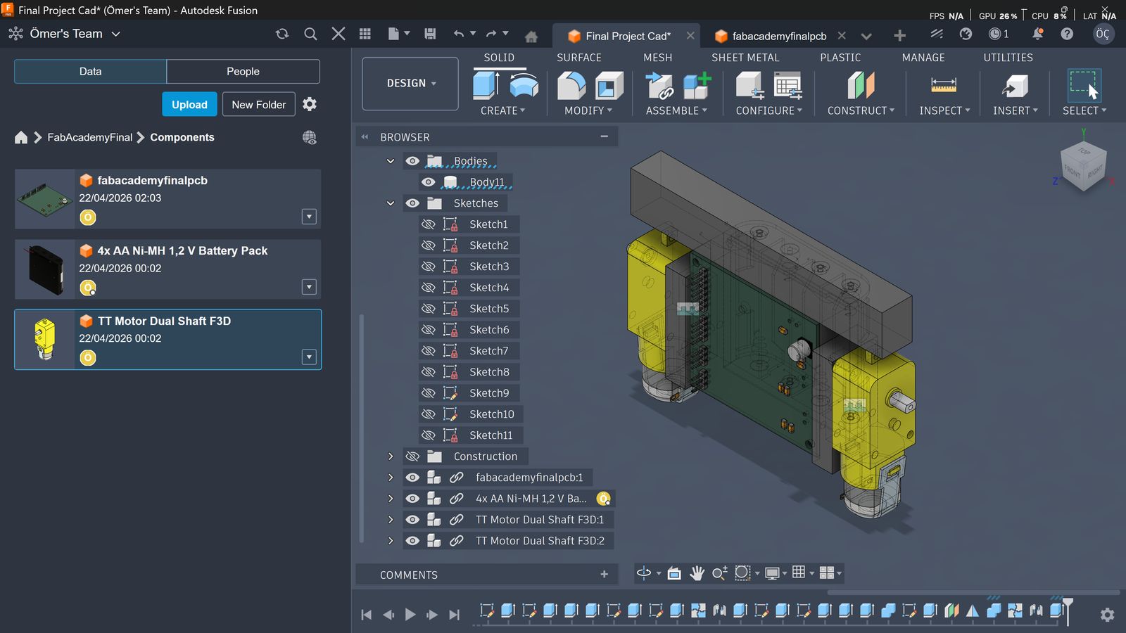
Then I rigid-grouped the motor assembly and used the joint function to join the motors to the main 3D part.
Then I extended the part forward to add caster wheels. I will add two casters, one on each side, to properly support the robot.
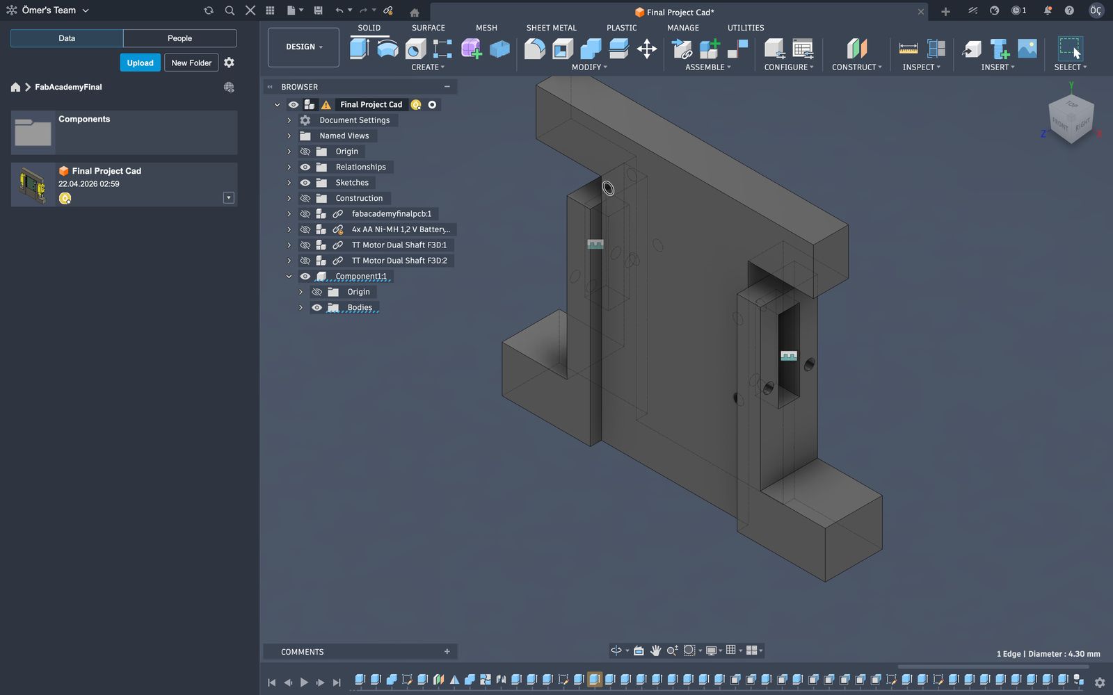
I expanded each hole to 4.3 mm in diameter so I could press in brass nuts (5 mm outer diameter). I made the holes slightly smaller so the brass nuts have material to bite and hold. I also decided to use Pololu 1/2" metal ball casters, so I added four holes for those brass nuts as well. I also added 0.2 mm chamfers on each hole to make insertion easier.
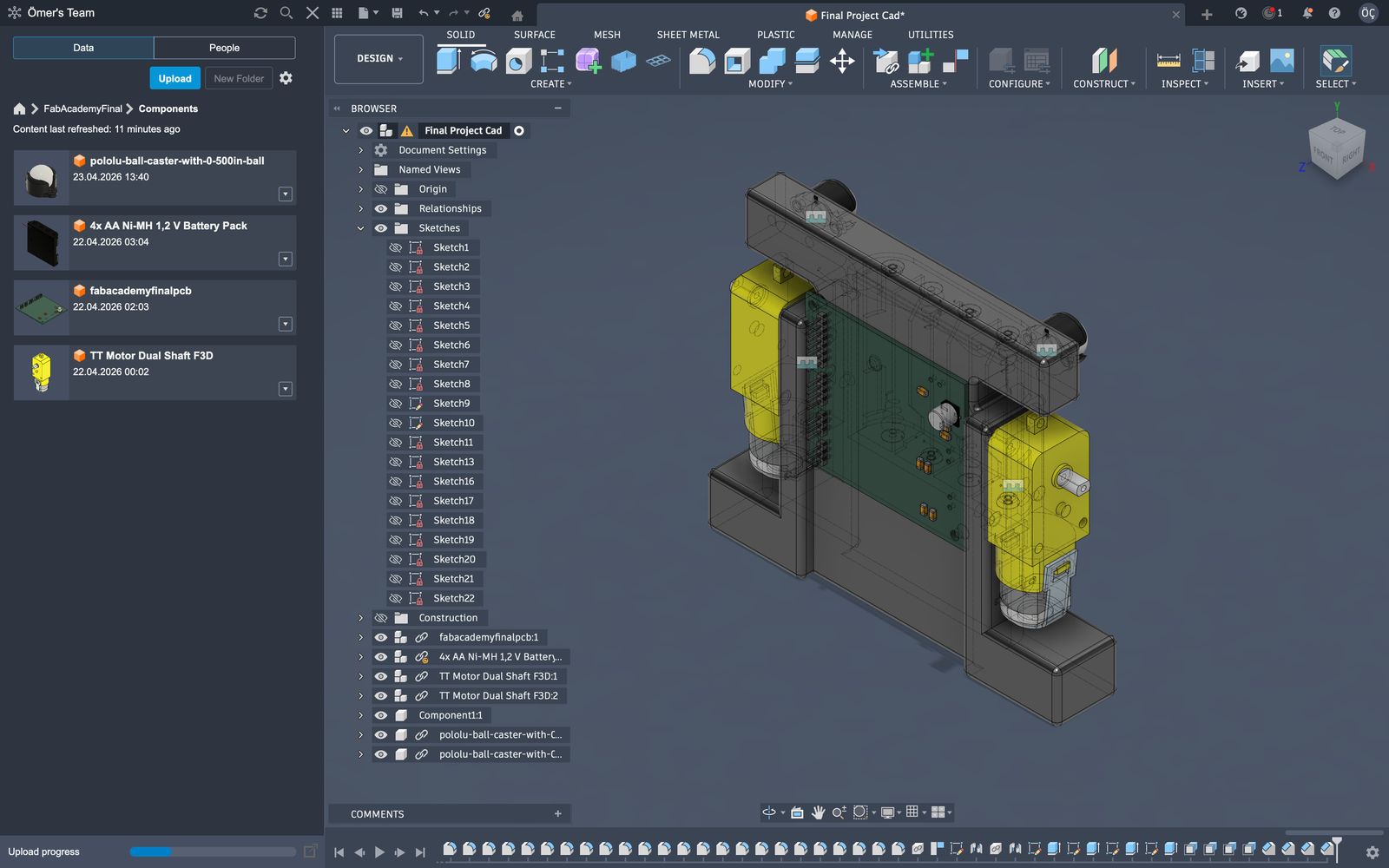
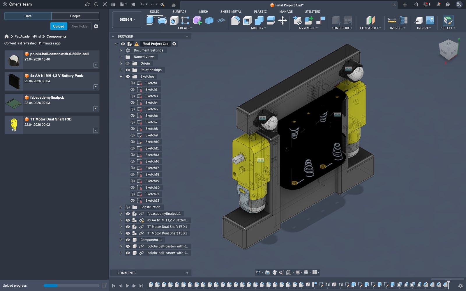
This is how the final design looks. I will use this to as the v1 body of my final project to see if everything works.
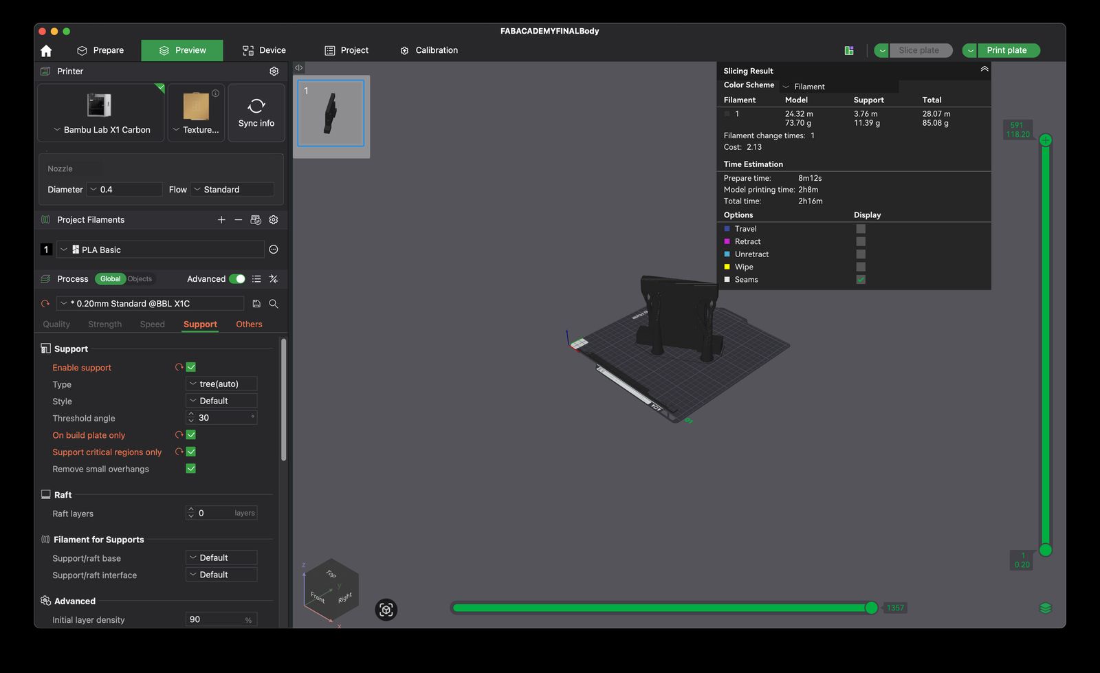
Then I sliced the files to send them to print.