Assignment:
Group Assignment Link • design a mold around the process you’ll be using, produce it with a smooth surface finish tha does not show the production process toolpath, and use it to cast parts • extra credit: use more then two mold parts • extra credit: make your own materials
Design
For this weeks assignment I want to cast a trinket for like a keychain futuring our Labs logo.
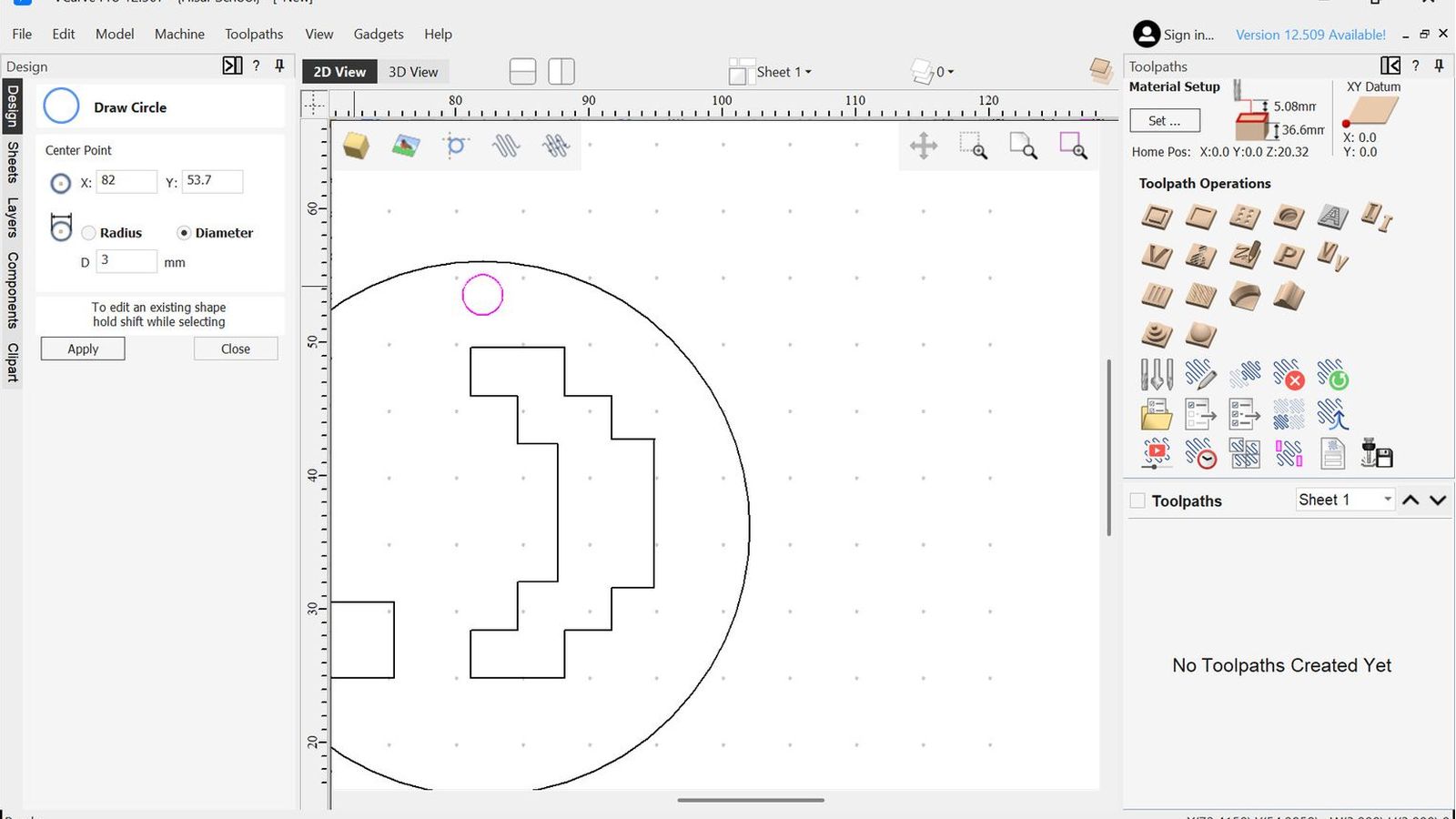
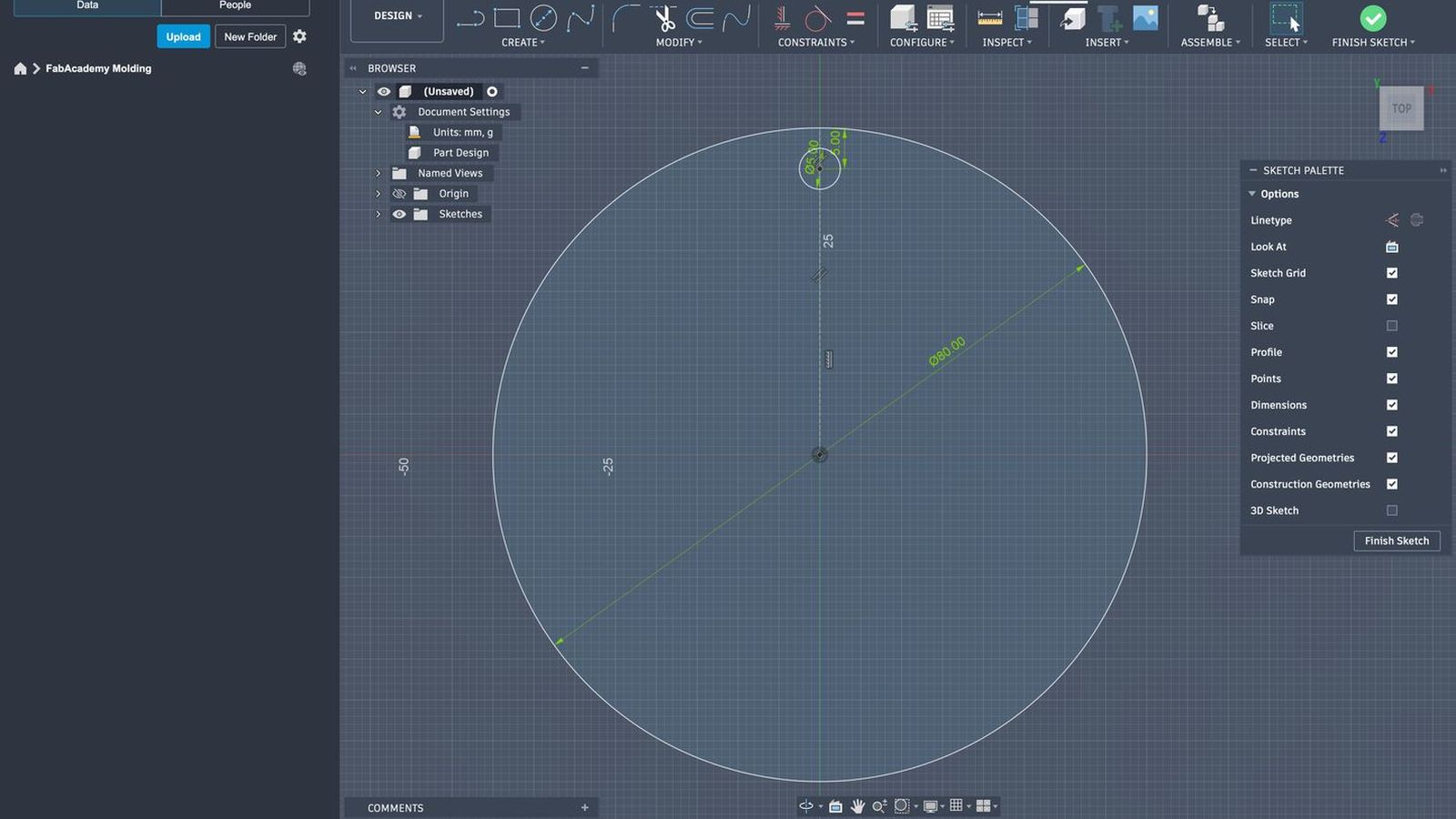 I started by making a circle for the base of my design I made it 80mm in diameters. I didn’t want it to be too small since it would make me use a smaller end mill which will make the procsses longer or make me switch more tools for some futures. I also added a 5mm hole on top of the base to attach it to something like a keychain ring or to a necklace chain etc.
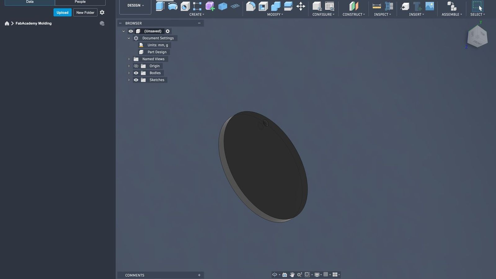 then I extruded it to an 5mm thickness so it would be rigid.
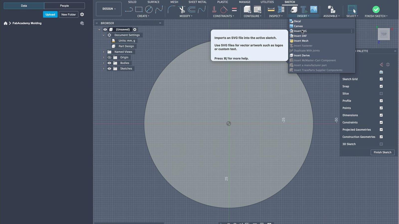 Then I imported our logo as an SVG file which I exported from canva.
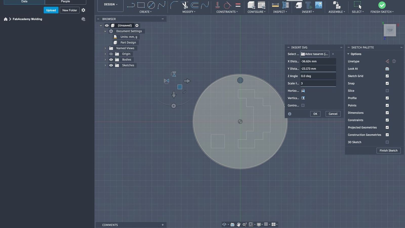 I scaled and moved the file so it would be in about the correct oriantation and size. I would want at least 3mm between every component of the desing including the design to the outer frame of the circle base and the line gaps between the design in self since I want to use an 3mm flat end mill this would Allow me to mill the design into a wax with least possible tool changes and paths later on.
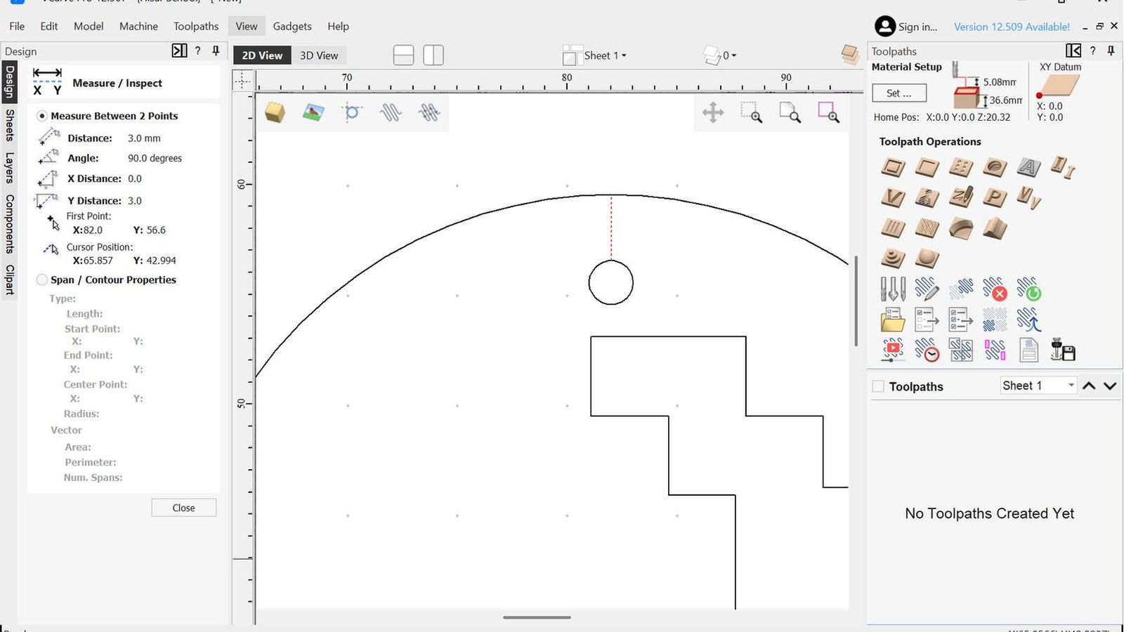
 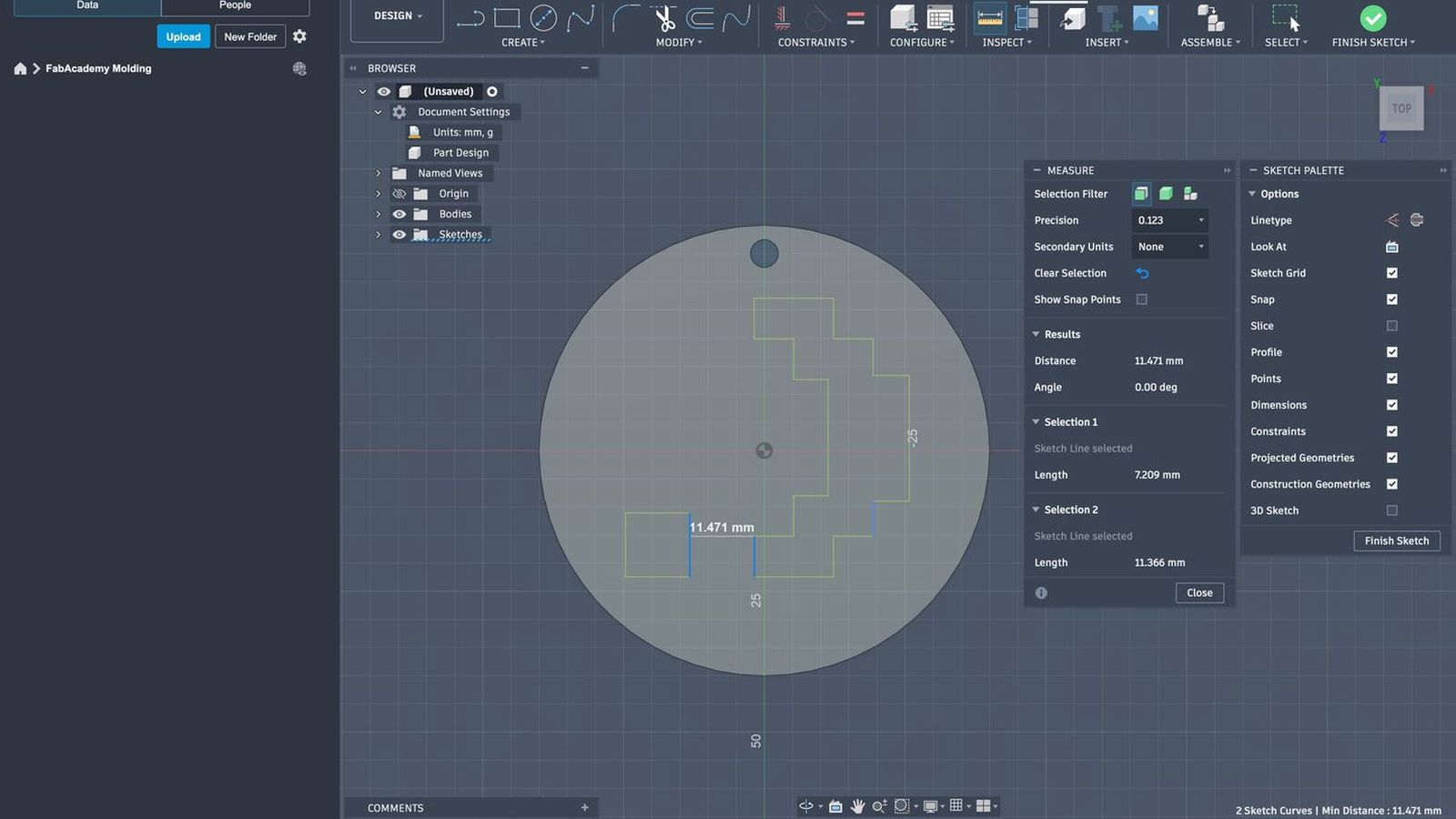 There is only two components in the desing the dot and the paranthesis and the gap between them is 11.471 mms on the closest point so we are good on that sideç Next I will se the minimum distance to outer frame of the base circle and see if a 3mm tool will fit there as well
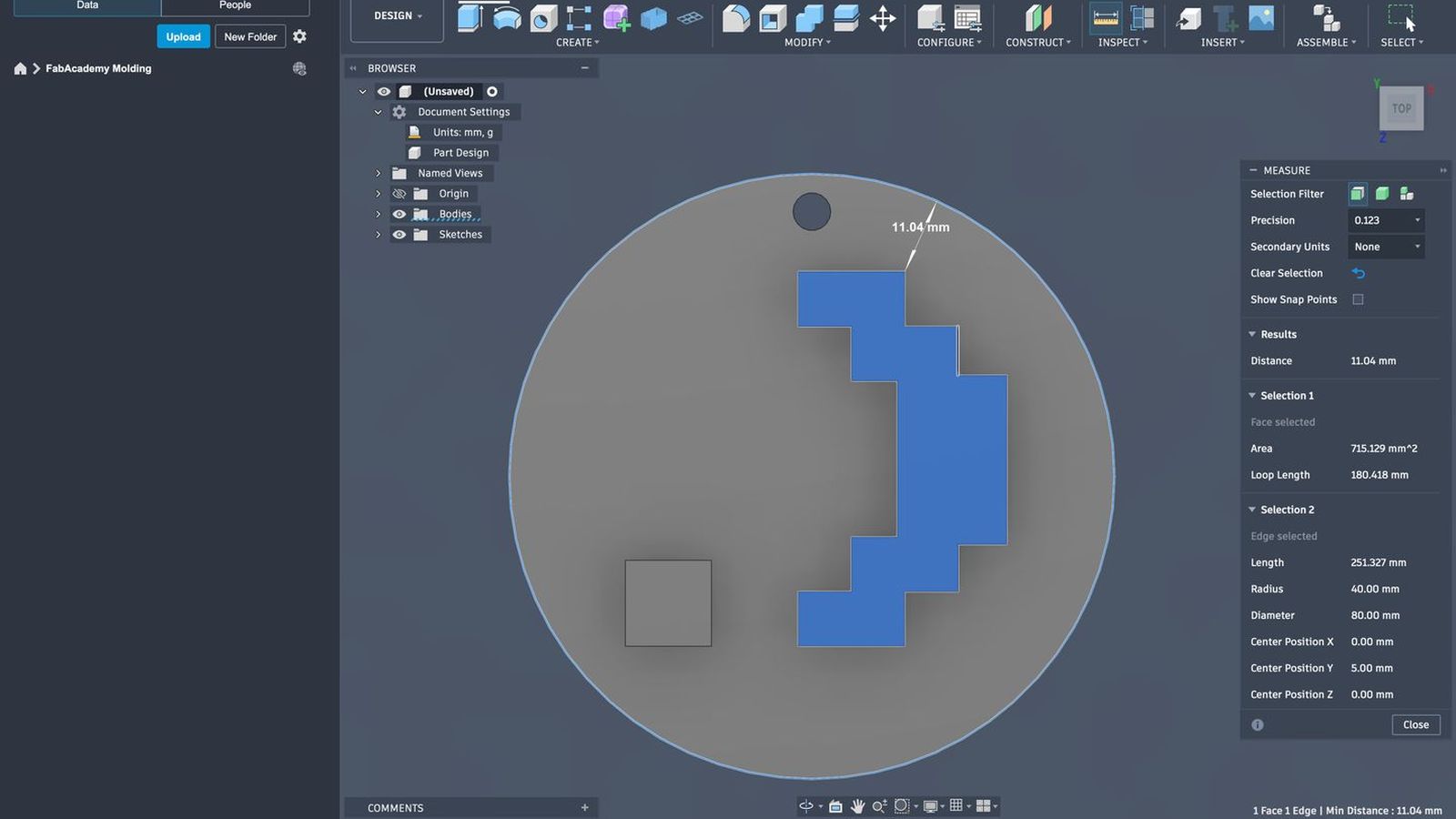
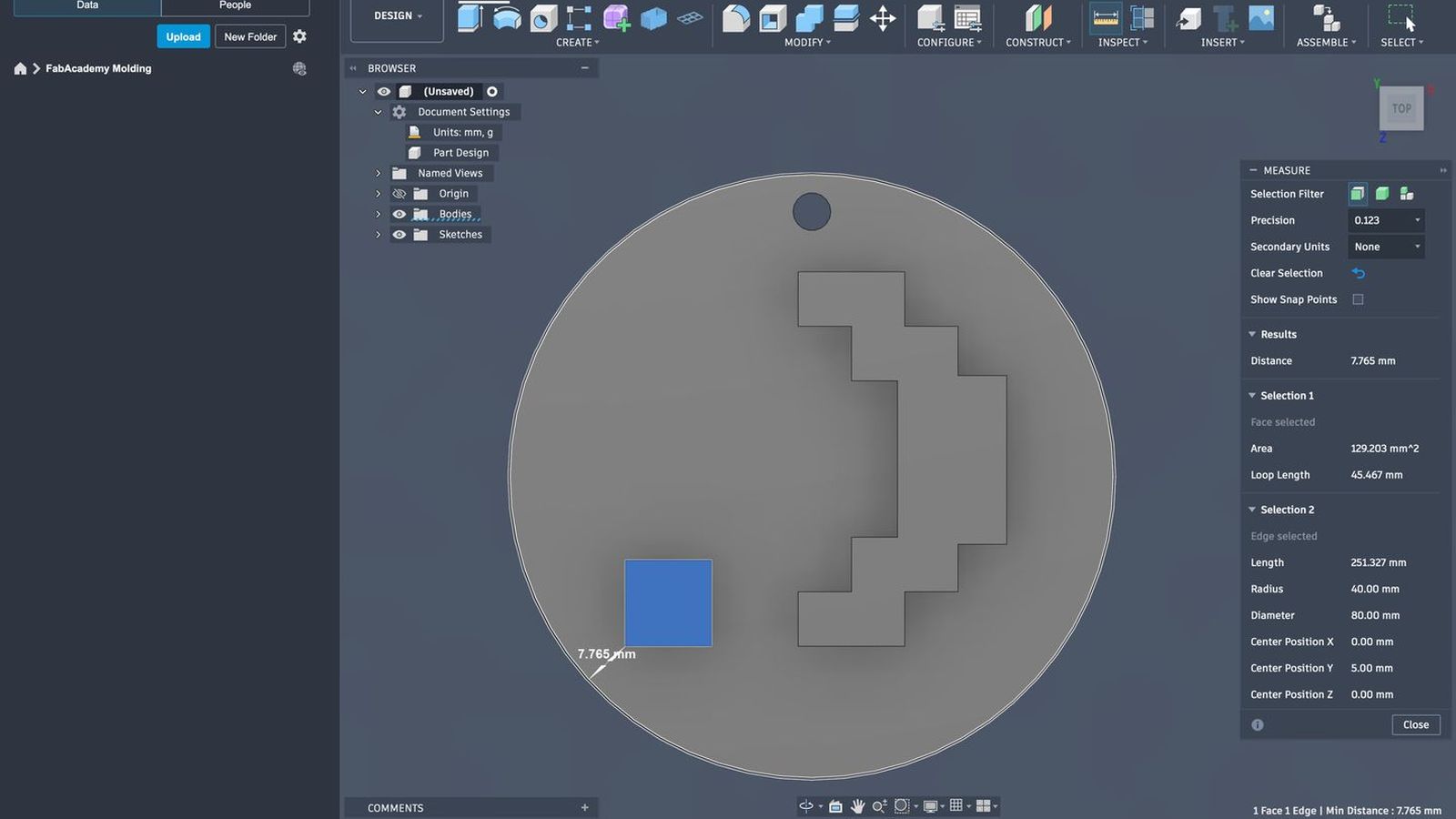 I use the inspection tool directly on the face so rather then finding the closest point by hand or eye balling it I will make fusion find the minimum distance for each component of the design. Since both of them clear my 3mm goal I will procced to export the design to vcarve to make toolpaths. I know it is a fairly simple design but since this is the molding and I have little experience with it I wanted focus on that aspect and make something a bit simpler.
Toolpath Generation and Wax Carving
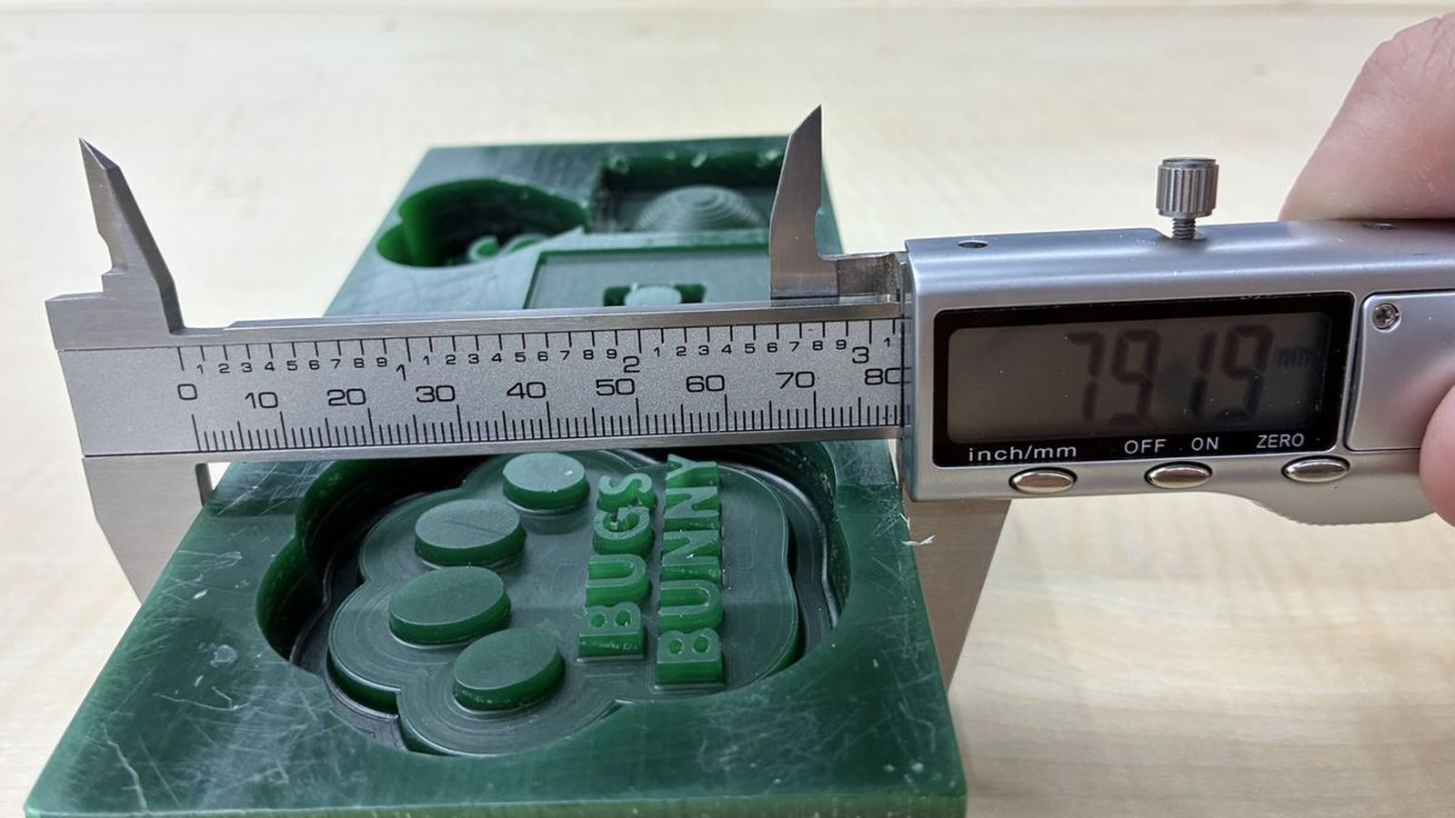
I will use v carve to generate tool paths using a 3mm one flute flat end mill to carve the wax for mold making. To first Configure I will mesure my stock wax. This wax has been used before so I will try to locate a part that I can fit my design into
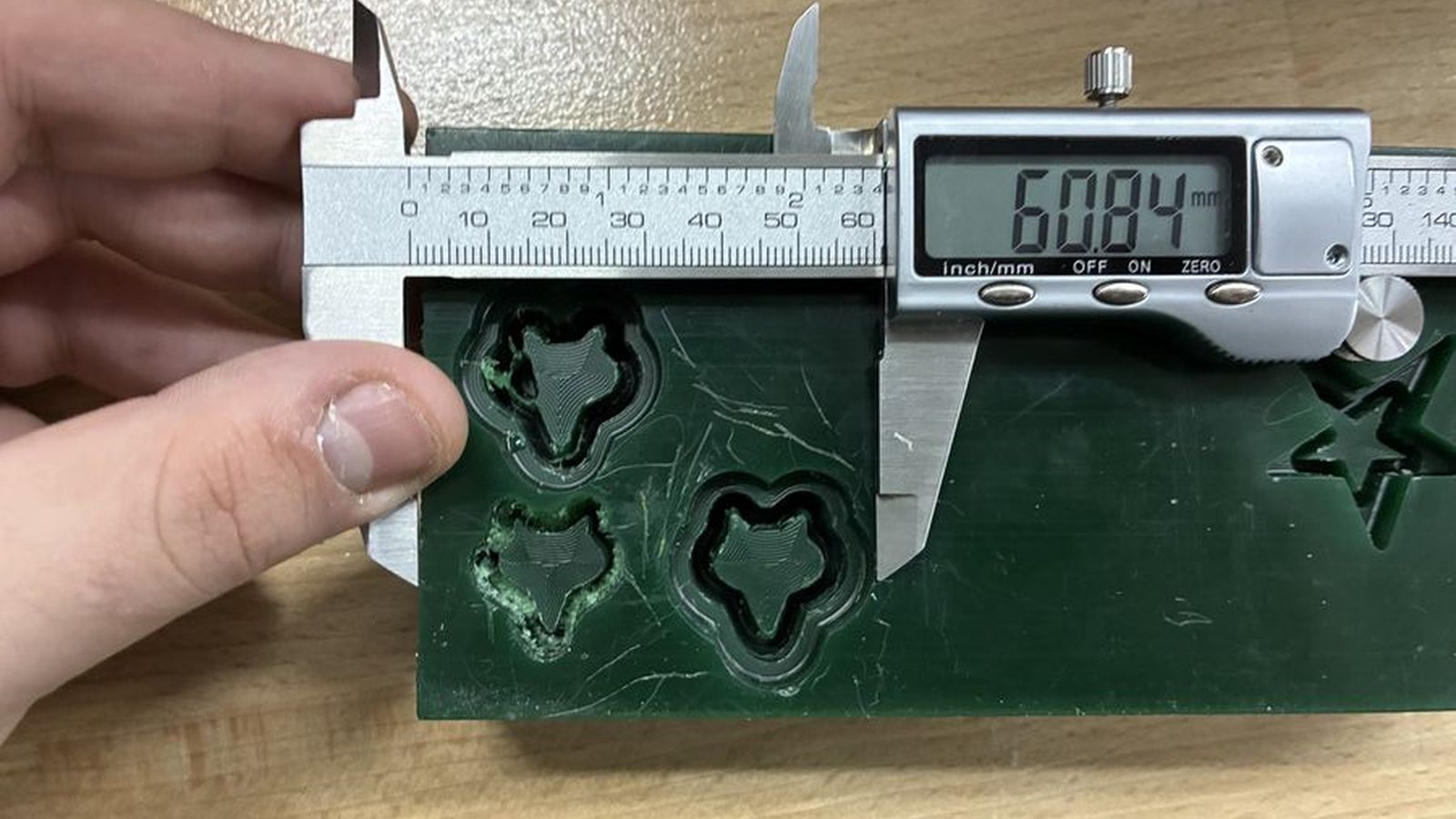
 Mesuring the Width
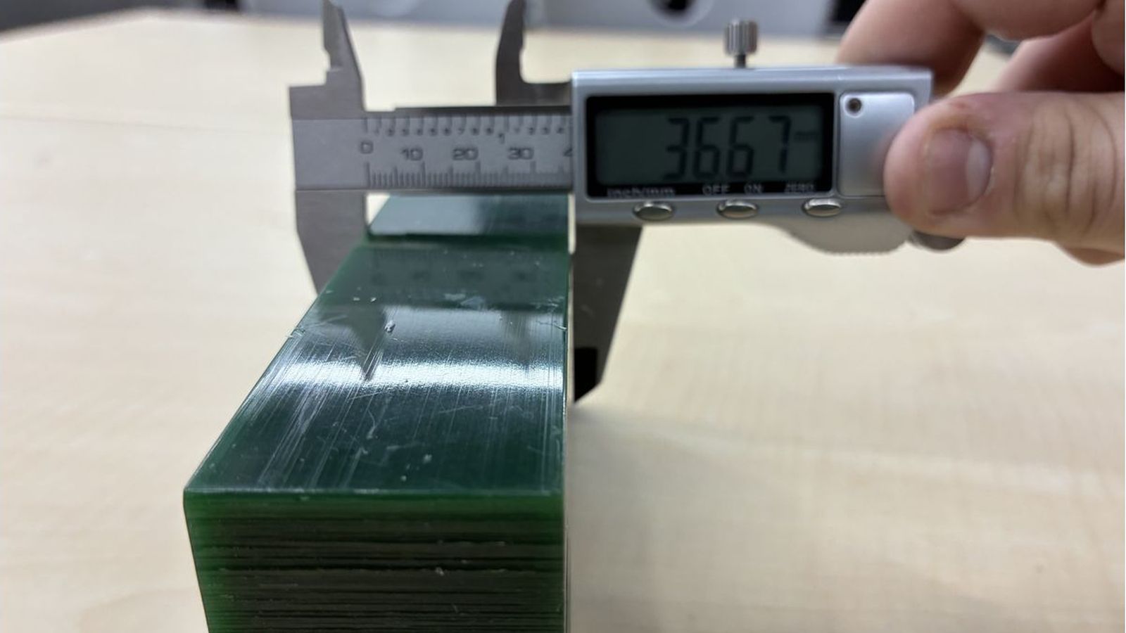 Mesuring the Thinckness.
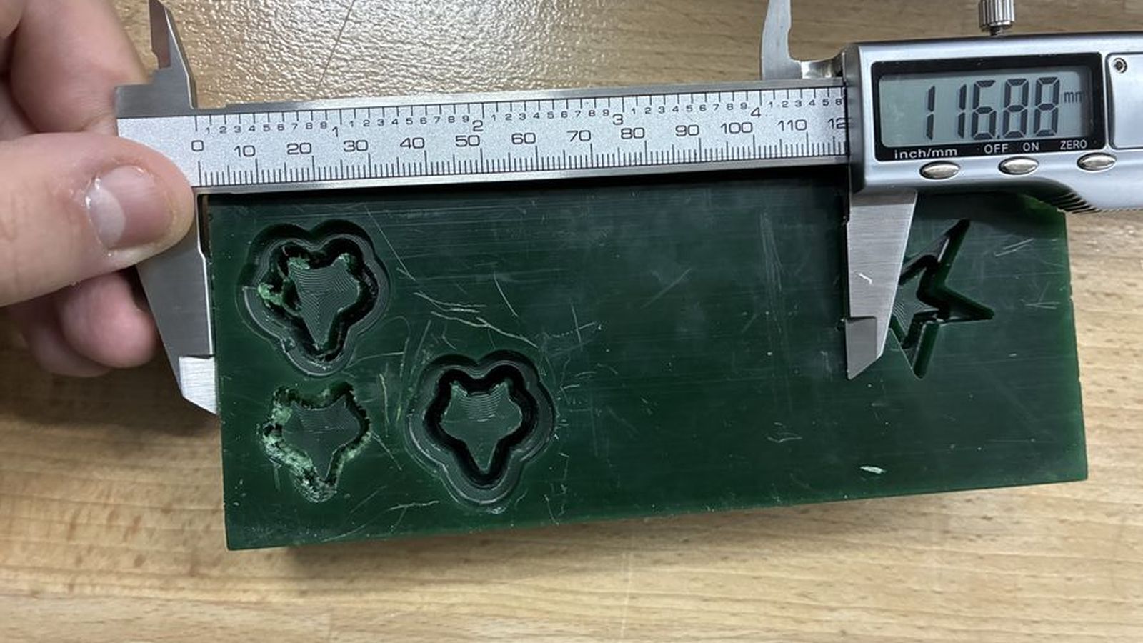
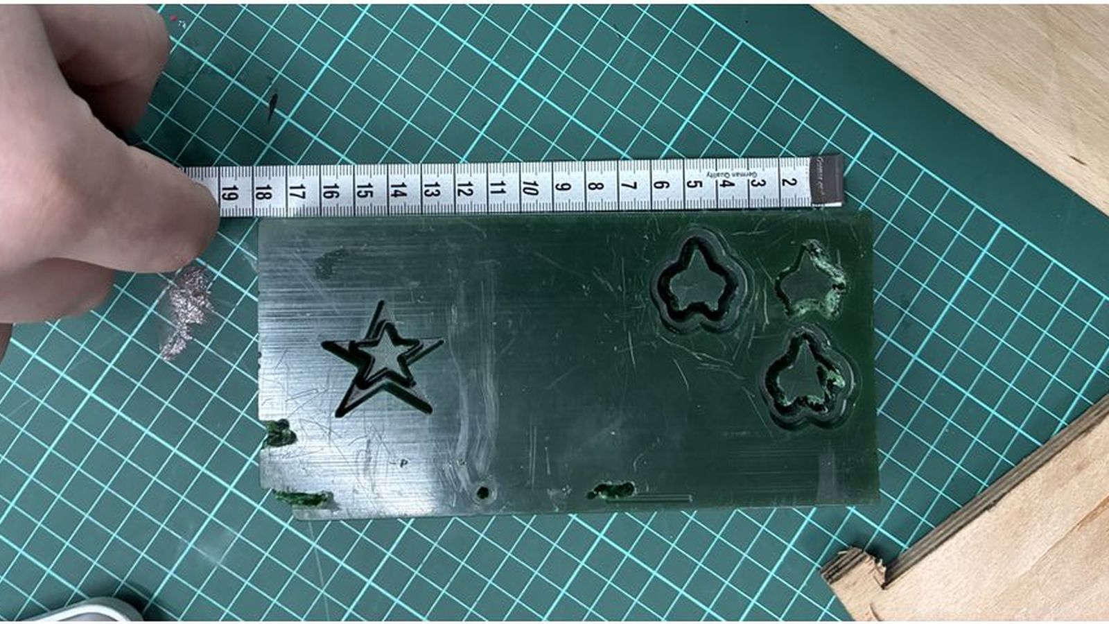 Mesuring the Length (Since my callipers only open about 150mms I used a mesuring tape)
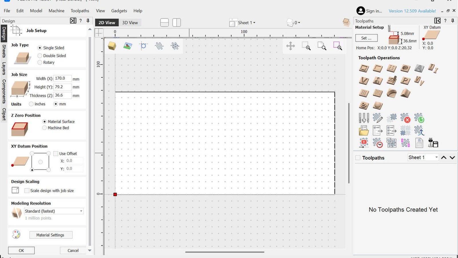
Then I entered theese values to vcarve to create the workpice I will be working on getting the datum point as the bottom left corner this will be important since this means I need to zero the XY postion of the machine on the bottom left corner of the workpiece I also selected the z zero position as the top of the workpiece material so I will Z zero when the tip of my bit touches the workpiece where I can use a trick to make it more easy and repeatable I will just adjust the z height of the machine a bit off the workpiece material making sure the bit has enough stickout to reach the most deep point of the design (10mm for my case) I will just zero the Z position and open the set screw on the machine to gently drop the bit onto the workpiece to ensure that my z zero position is correct rather then adjusting step size and carefully finding the z position each time I change bit(I will use one bit as mentioned in this case but the trick still works).
Mesuring the Length (Since my callipers only open about 150mms I used a mesuring tape)
Then I entered theese values to vcarve to create the workpice I will be working on getting the datum point as the bottom left corner this will be important since this means I need to zero the XY postion of the machine on the bottom left corner of the workpiece I also selected the z zero position as the top of the workpiece material so I will Z zero when the tip of my bit touches the workpiece where I can use a trick to make it more easy and repeatable I will just adjust the z height of the machine a bit off the workpiece material making sure the bit has enough stickout to reach the most deep point of the design (10mm for my case) I will just zero the Z position and open the set screw on the machine to gently drop the bit onto the workpiece to ensure that my z zero position is correct rather then adjusting step size and carefully finding the z position each time I change bit(I will use one bit as mentioned in this case but the trick still works).
 Setup photo
Then I located a open spot to carve my design into
Setup photo
Then I located a open spot to carve my design into
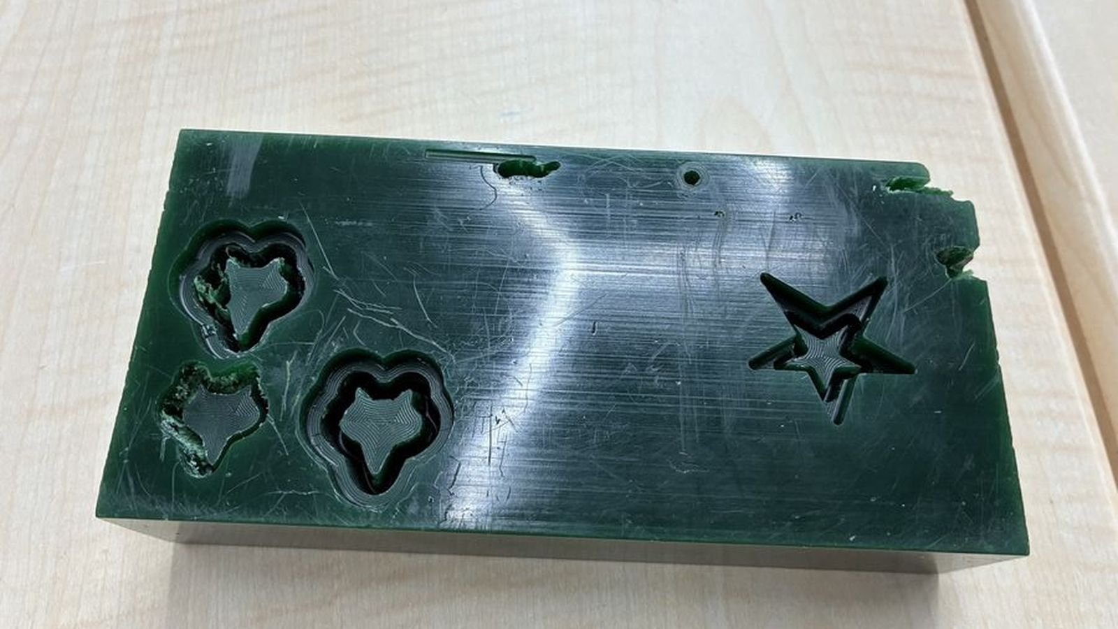
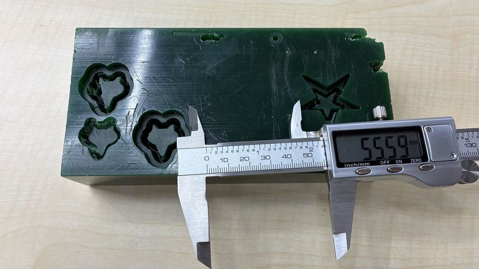 But sadly it is not big enough there is only 55.59mm between the walls of the previously carved designs where my design hada 80mm diameter circle so I will scale the design to %50 making the circle 40mm in diameter.
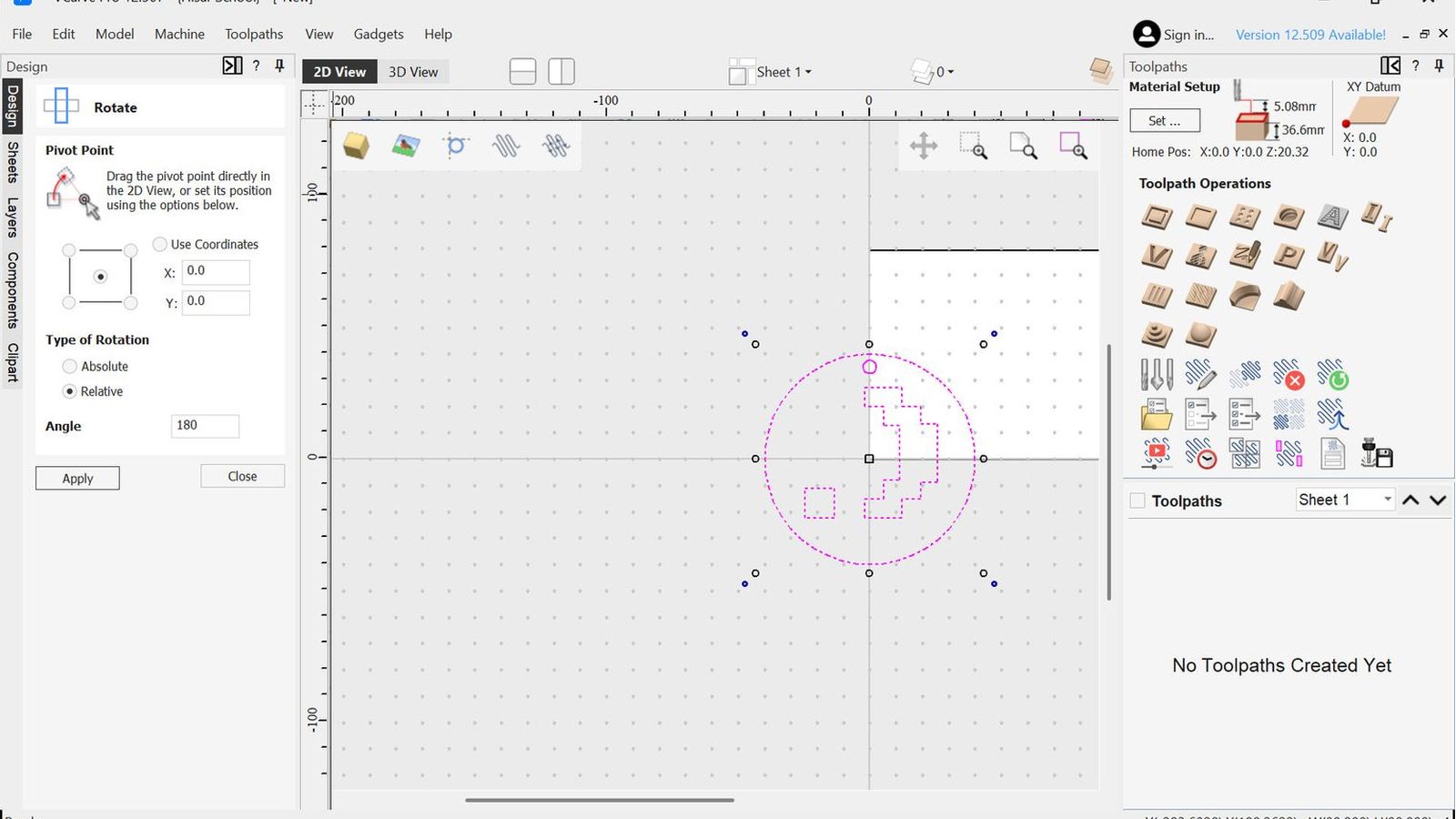
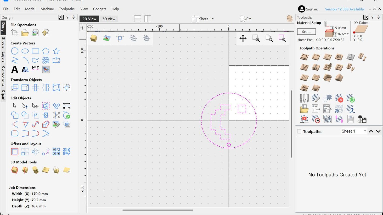 So I imported my design into v-carve using the import vector option. rotated it 180degrees and uniformly scaled it down to 50% of the original size.
 Rotate Photo
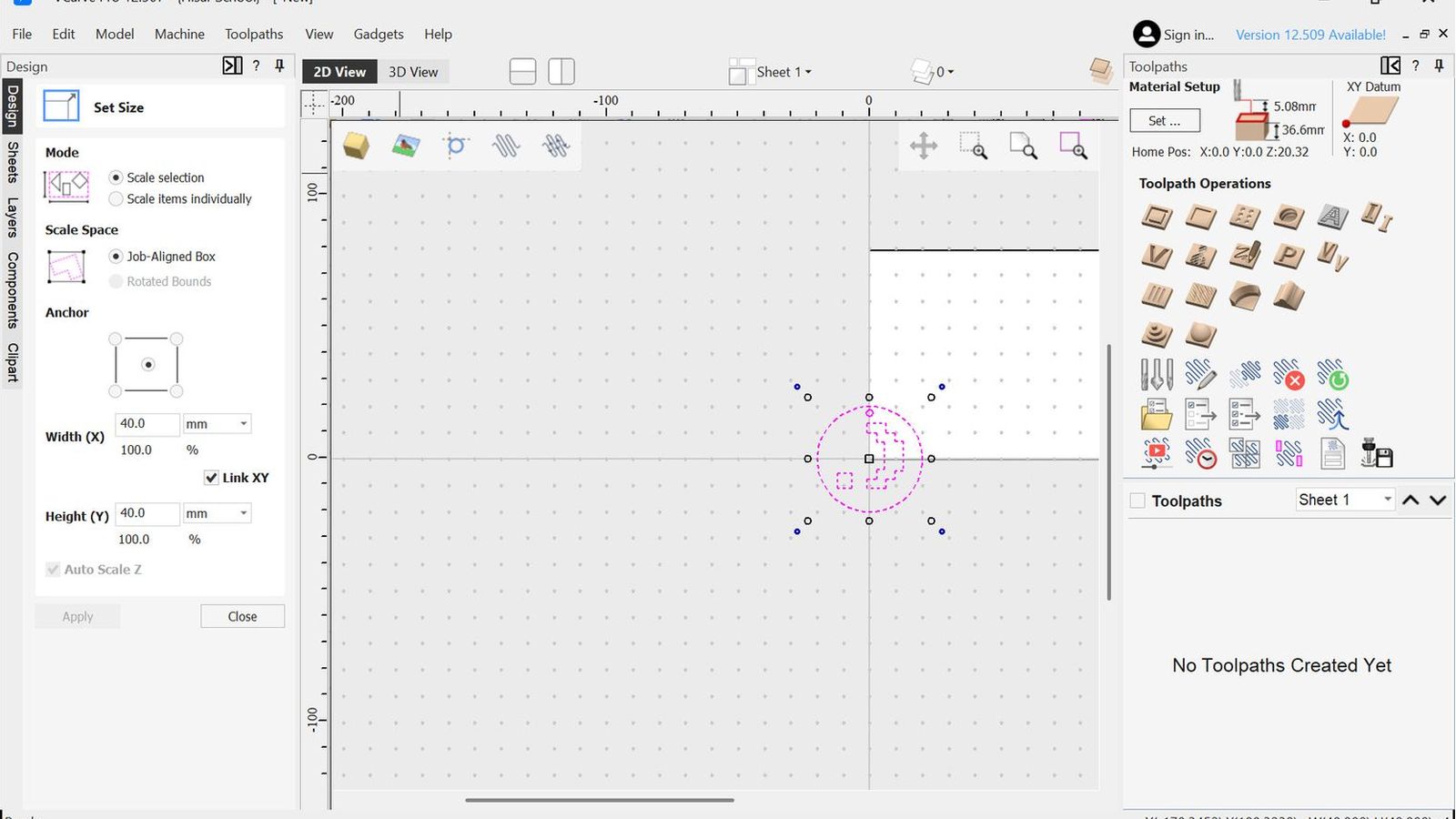 Scale photo
 Then I mesured the most outer walls of the prevously carved designs from the left side of the wax block since that is my datum point to move my design so it would be between theese two points so It wouldn’t collide with the previously carved designs. I used the move selection option in absolute move option so I would move the selection relative to the workpiece on the obsulute cordinate system where the relative option would move it relativly to it self(for example If I enter 62mm on the X position in absolute mode v carve will move my selections anchor point which is the point of the design that will be taken as refernce 62mm away from the datum point where if I used relative it would move 62mm away from the current position of the anchor point of the selection)
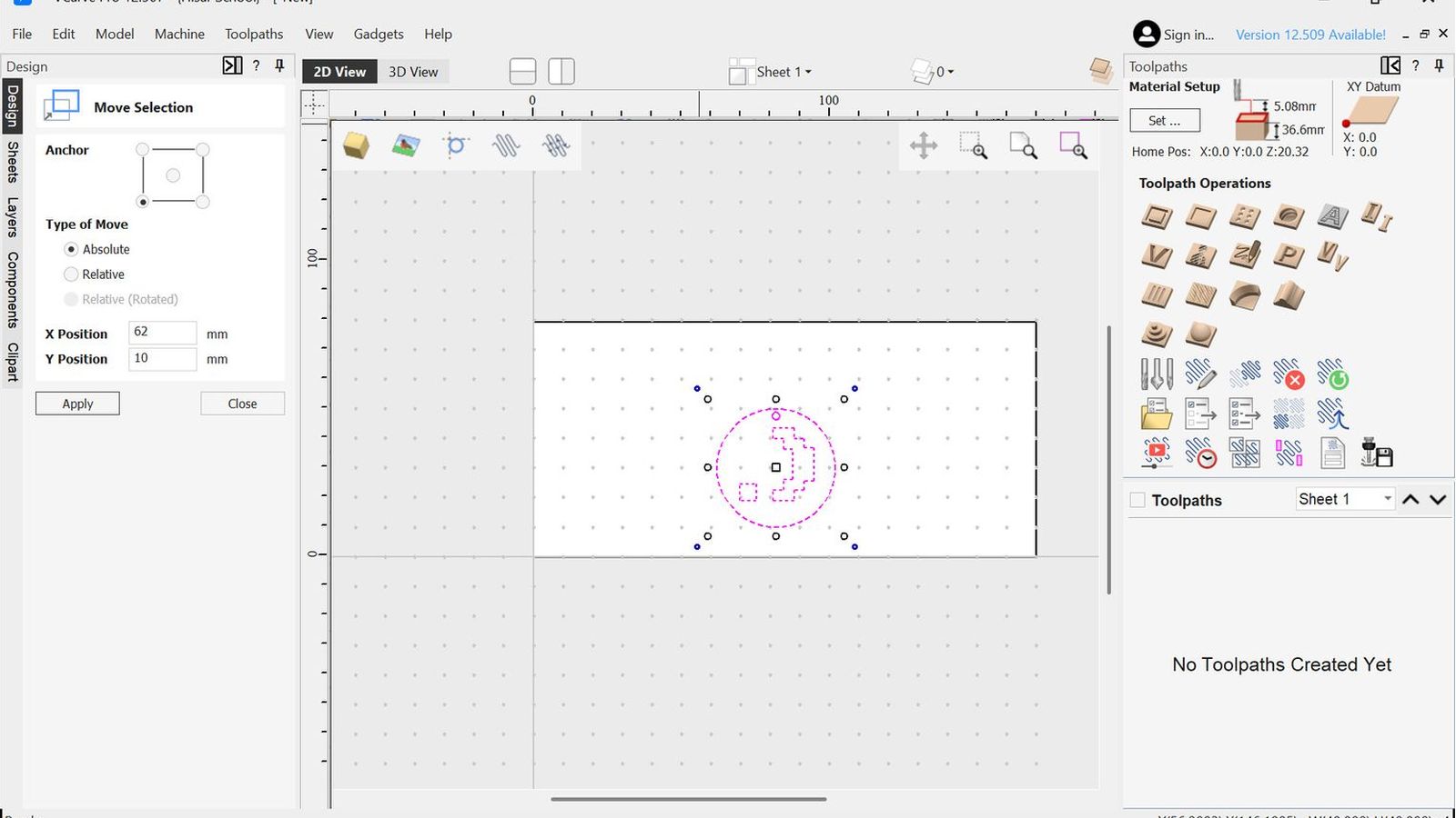
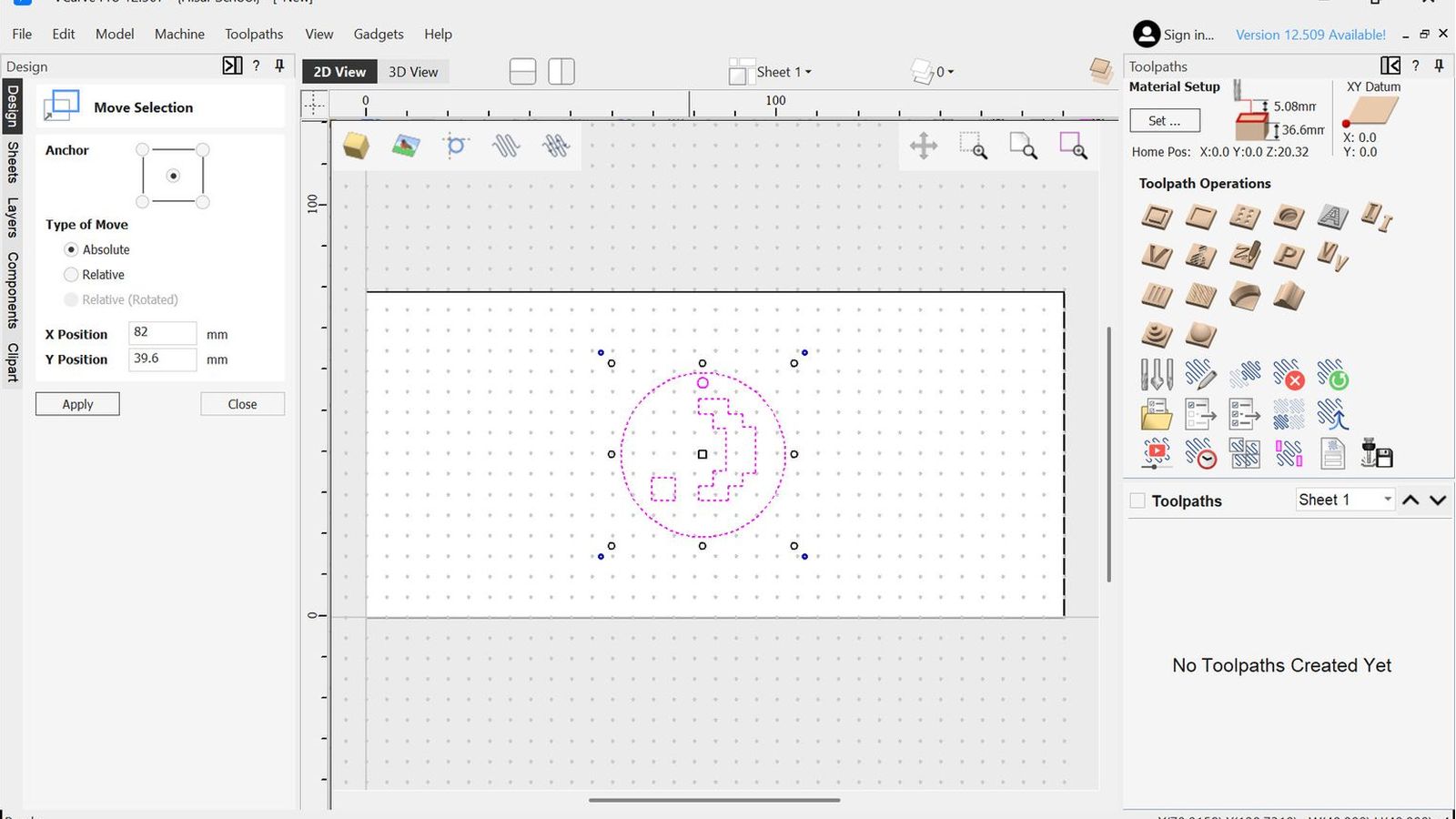
So using this function I centered my design on the y axis and Moved the most left point my design 62mm away from the left side of my wax. Then I configured my bit I will use the same bit but with 2 different configurations one for roughing and the other for finishing so it would achive a good surface finish but also have relatively more aggressive toolpaths to remove material as fast as possible to keep machining time relativly shorter then using the finishing config for every cut I used this site to reference chipload since my bits’ manufacturer doesn’t have an chipload table online
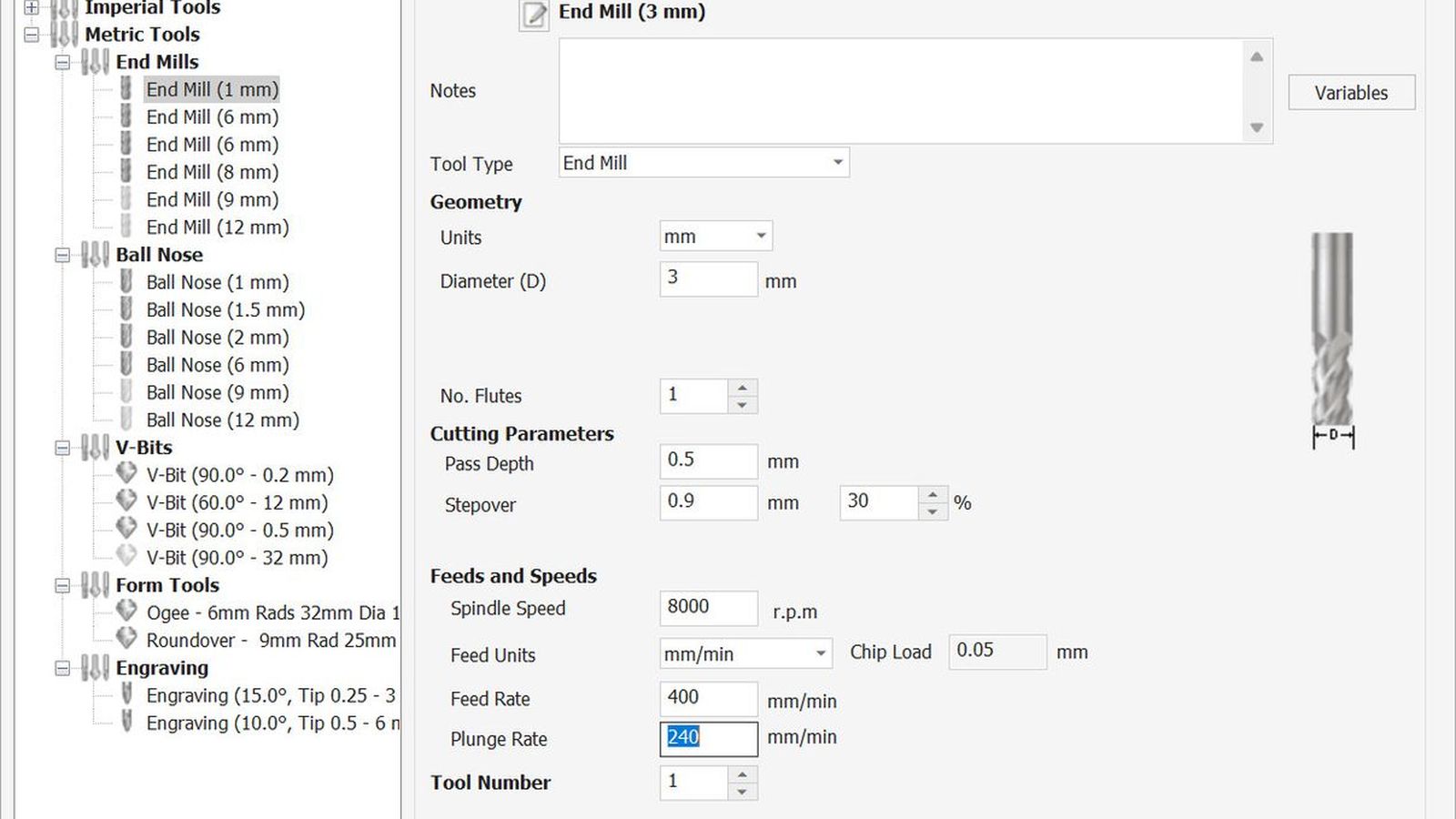 Roughing Tool Config
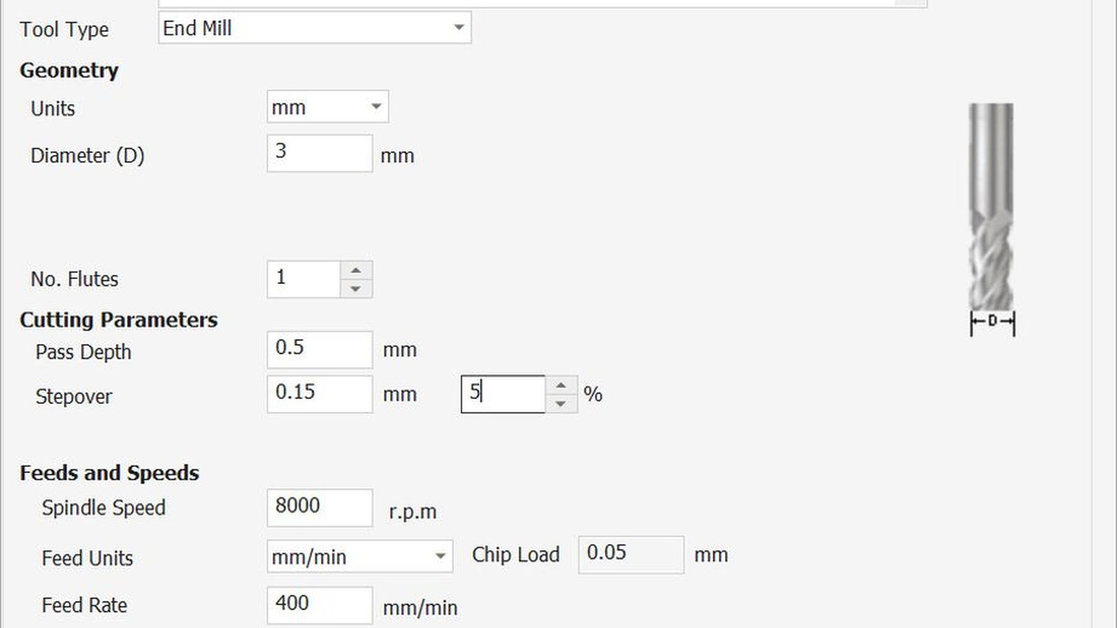 Finishing tool config
the main diffarance of these two configs is the stepover which determents the radial engagment of the bit to the material on pocketing operations. My roughing bit has 30% step over to remove material quicker and the finishing has %5 to achieve a better surface finish. It is the percentages from the total diameter of the tool.

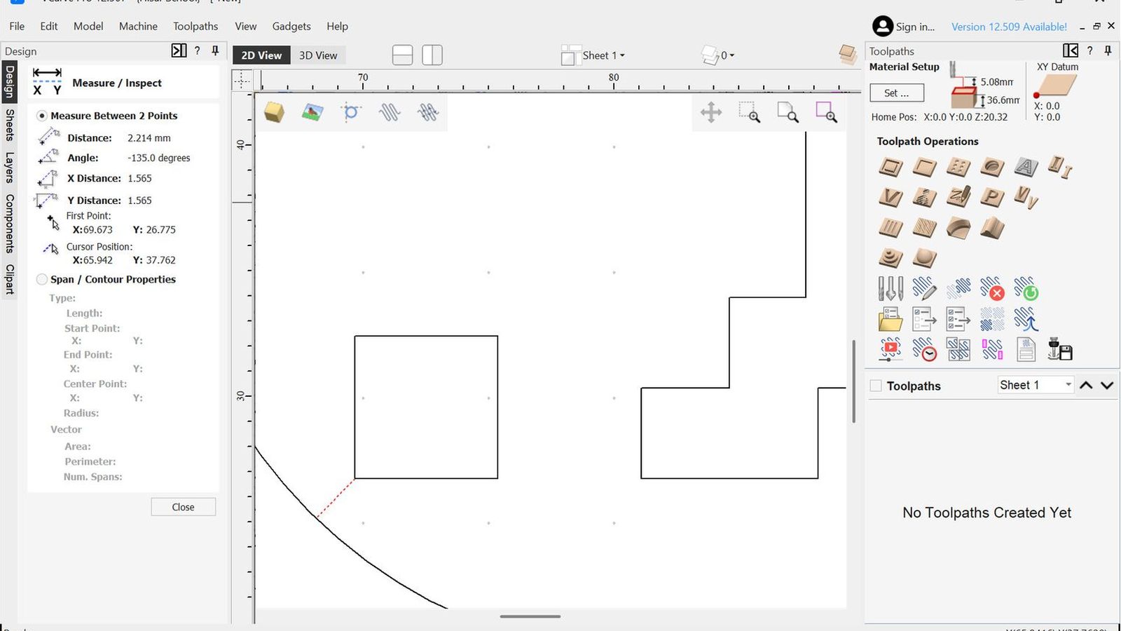
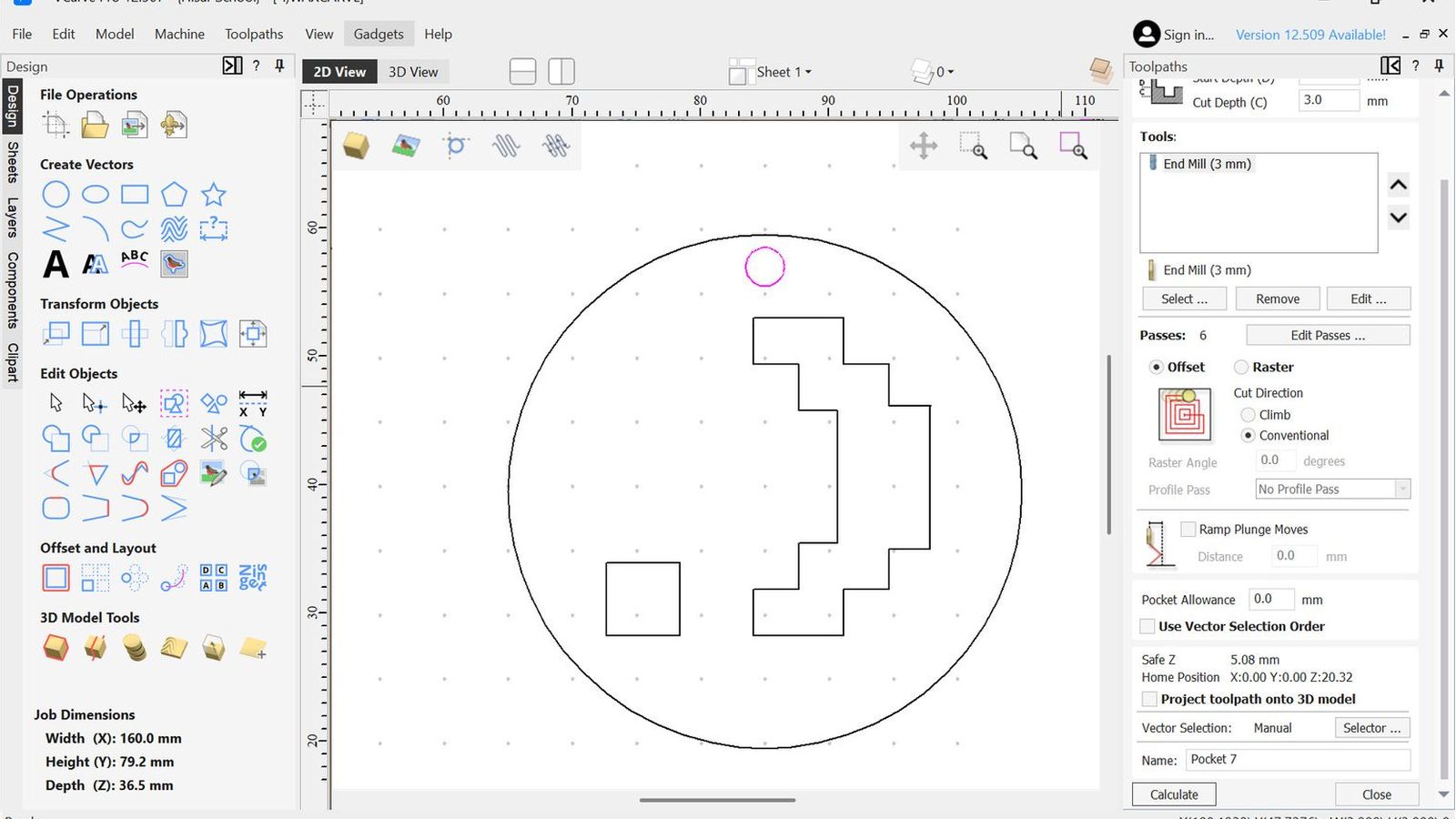
 I then measured design to ensure that the 3mm bit would fit everywhere and I didn’t had to use a smaller bit for some operations.
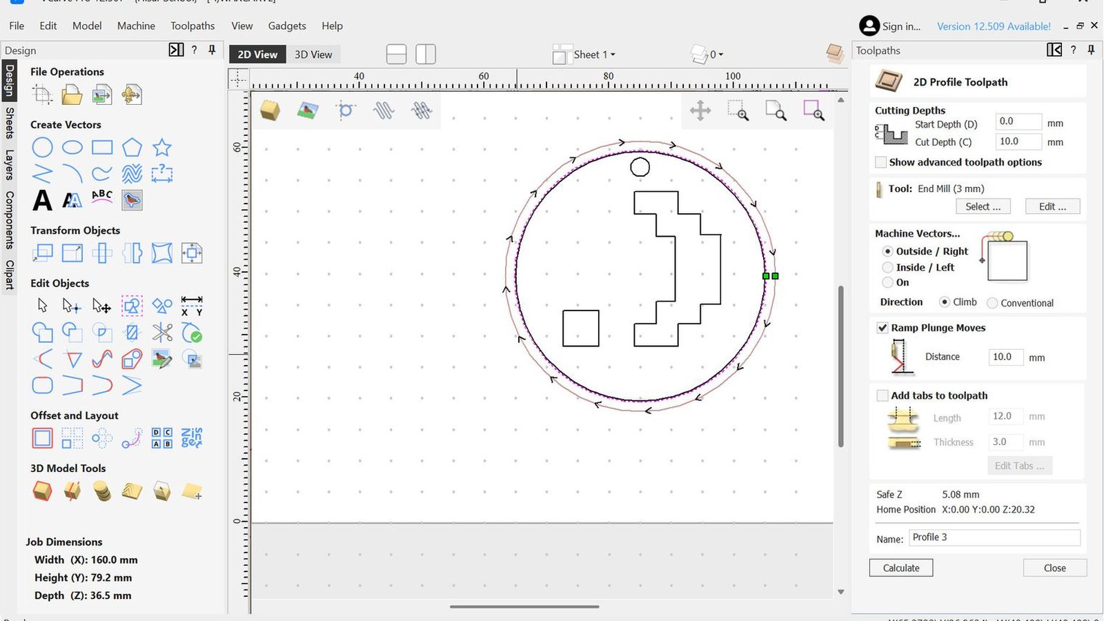
 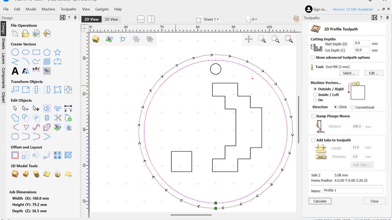 I started by creating a profile toolpath around the outer circle of the design 10mm deep which is the full width of my design this will act as the walls of the mold
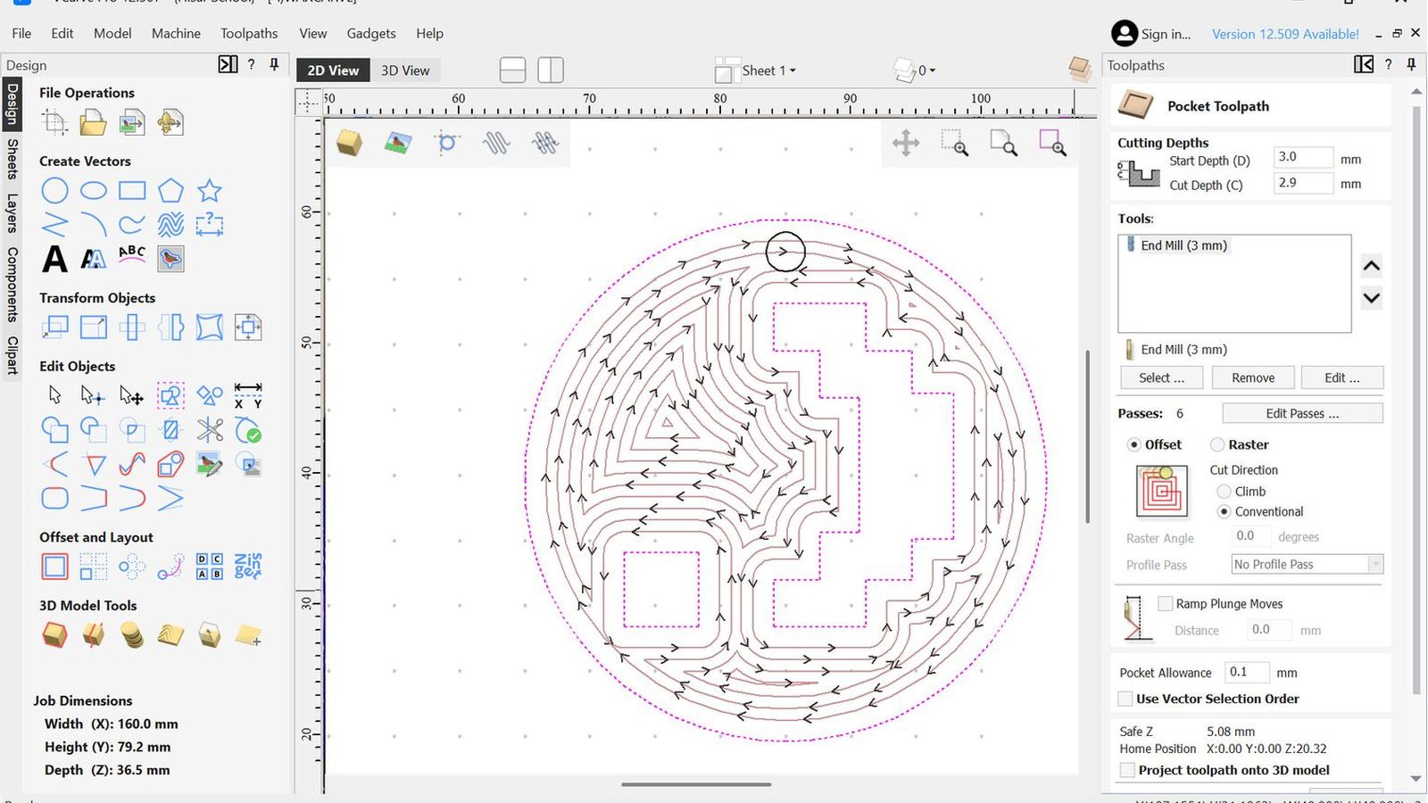
 Then I made a roughing pocketing toolpath that has a 0.1 pocket allowance 3.9 deep this would leave 0.1mm from the walls and the bottom of the pocket for a finishing pass.
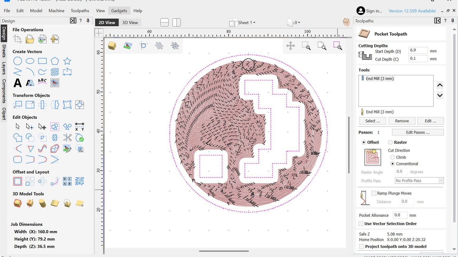
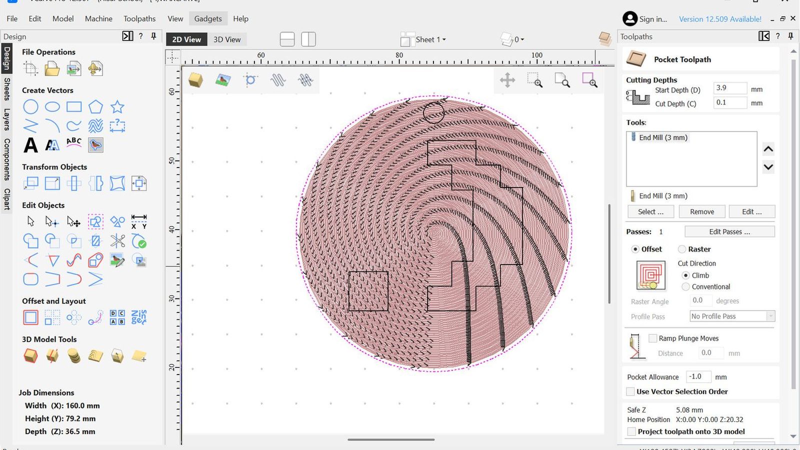 Then I configured the finishing pass which will start from 3.9 and cut 0.1 mms with -1 pocket allowance It is also in reverse direction to the roughing tool path.
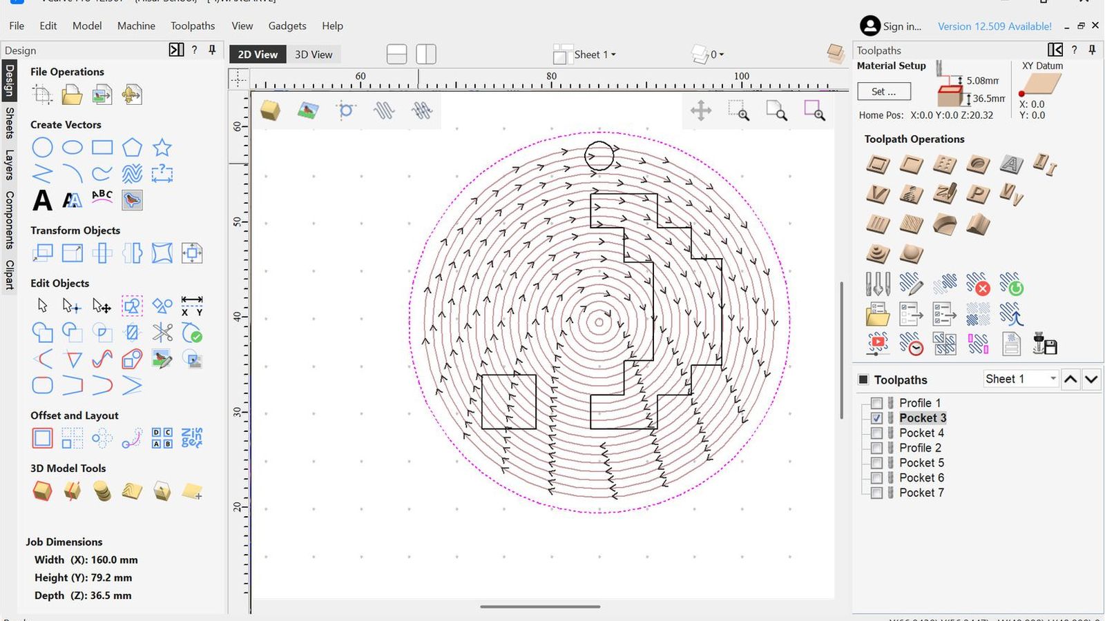
 Then I configured a roughing toolpath for the design it self same as the other roughing toolpath
 Then a finishing toolpath for the design as well same as before
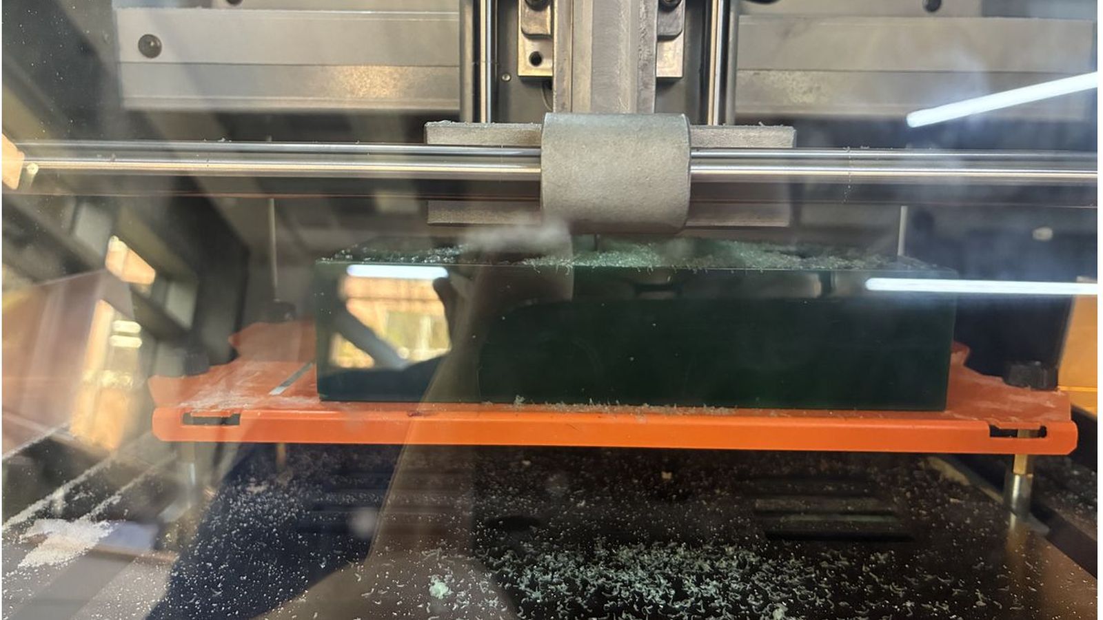
 Then I made a pocket operation for the hole but since my hole diameter is the same as my tool diameter It will just move in the z axis. Then I outputted all the toolpaths after confuguring the xy and z zeros to SRM-20 directly from vcarve since it has a post processor on vcarve I can just output to the machine directly from the save file window. I fixed my workpiece using double sided tape to the machine bed.
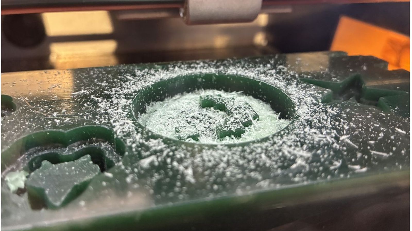
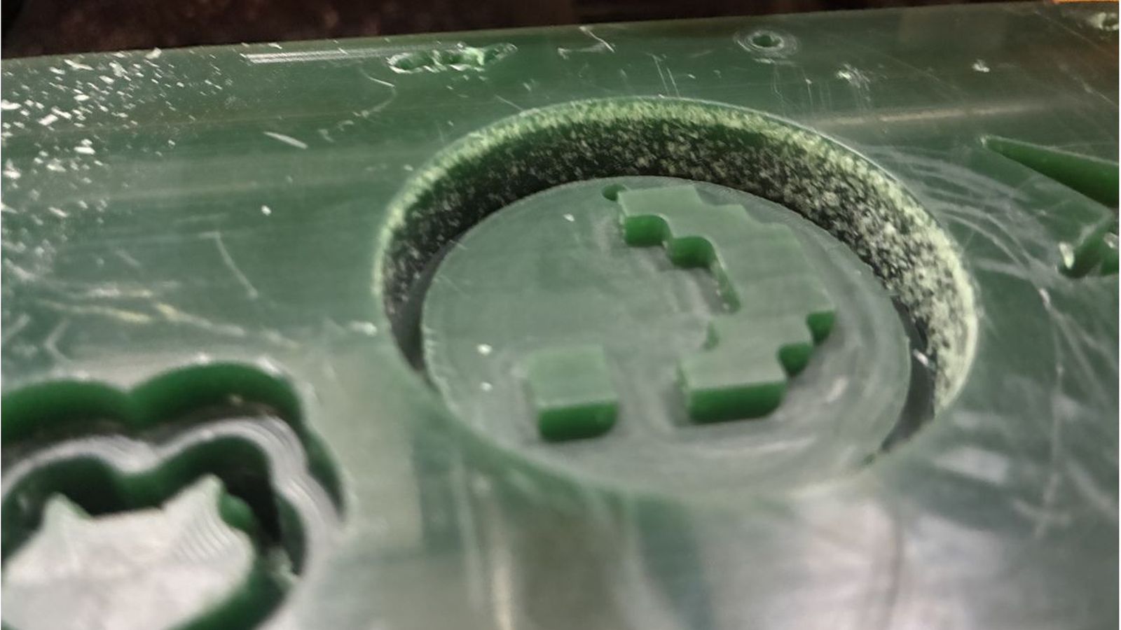 The outer wall of the wax was rough since the profile toolpath had %100 radial engagement. So to fix this I offsetted the outer circle of my design by 0.2mms
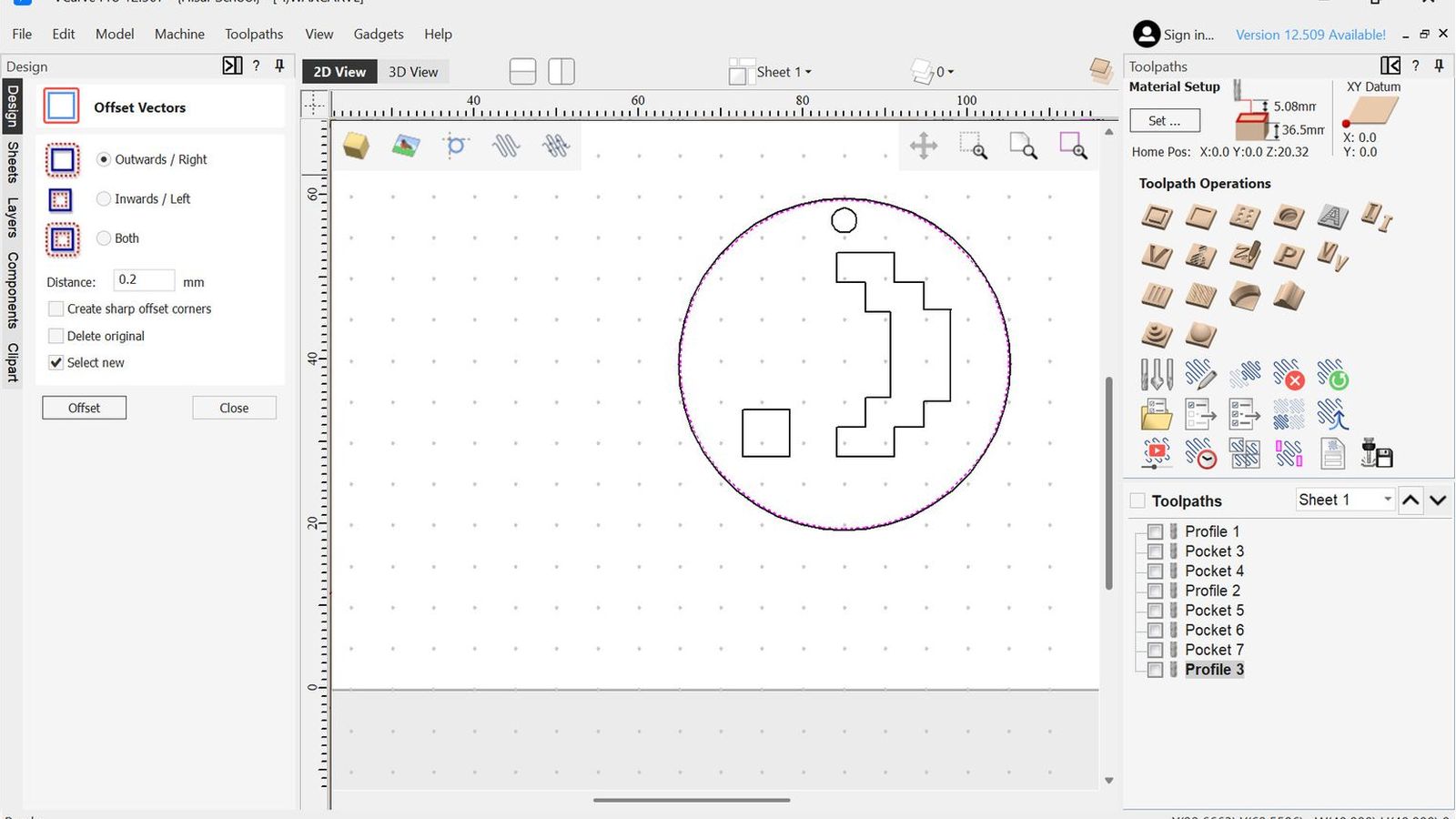 and confugered a profile path on that to finish the outer walls
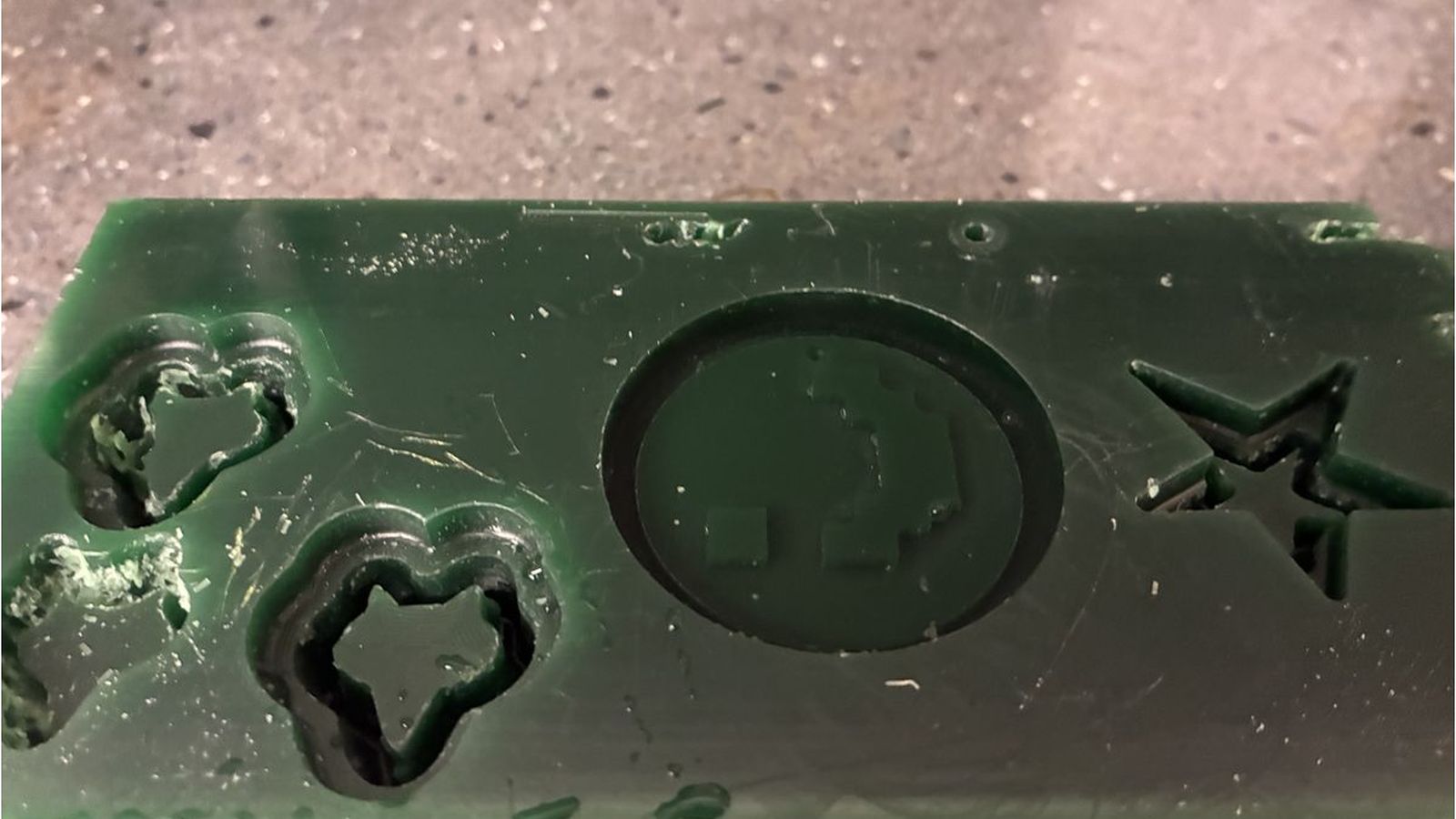
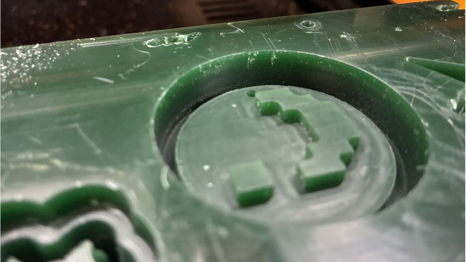 This fixed the problem for the outer walls.
Mold Making
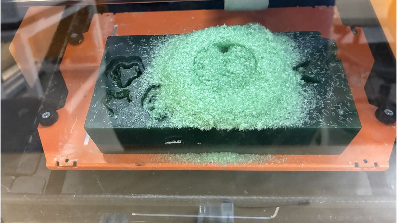
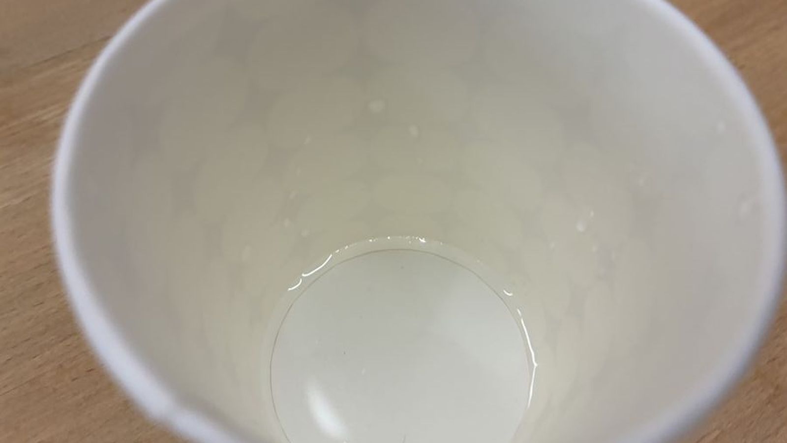
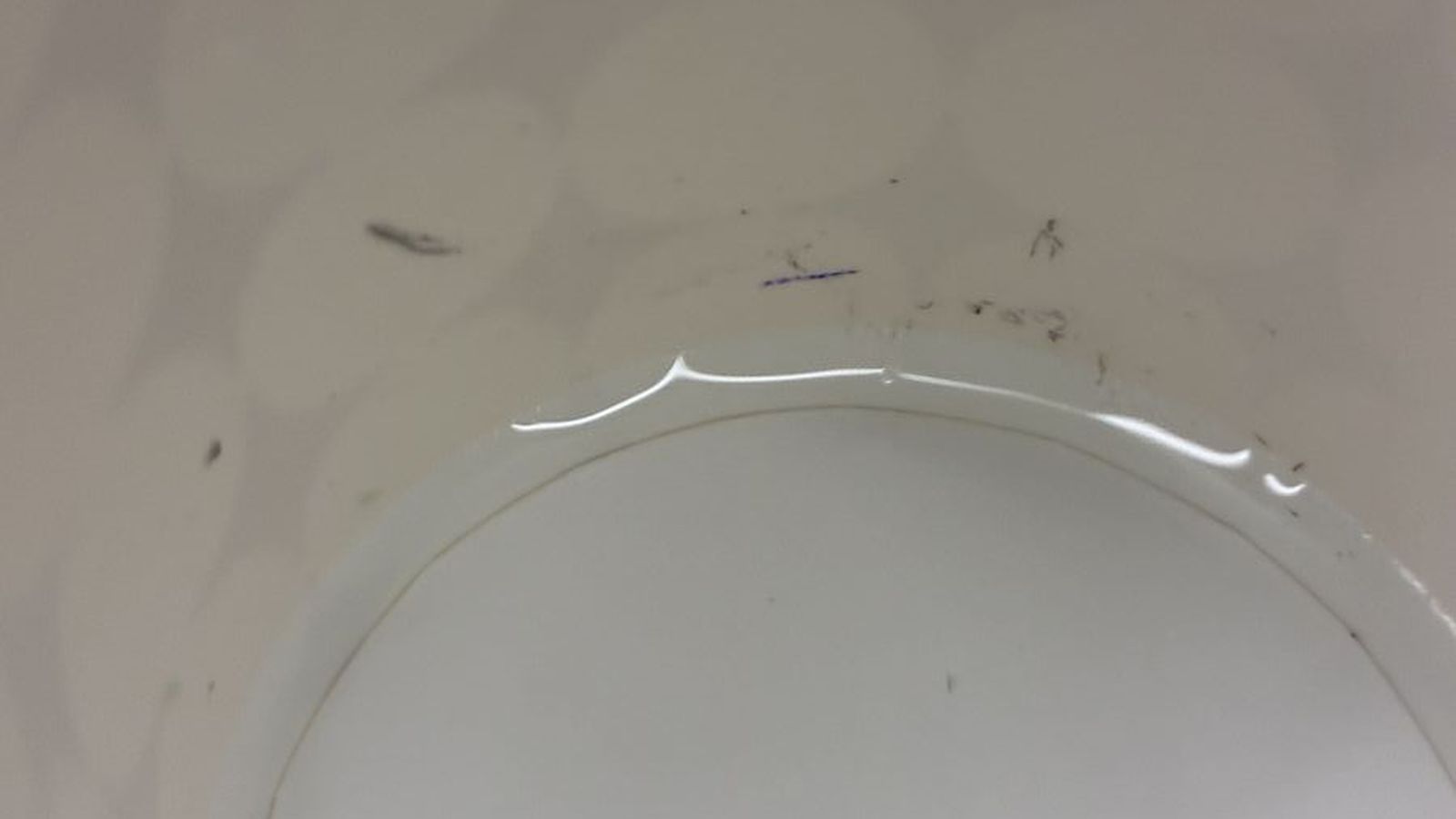
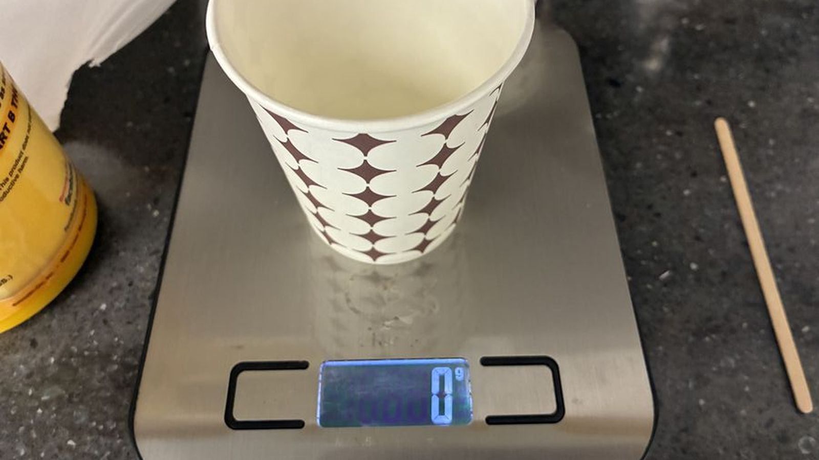
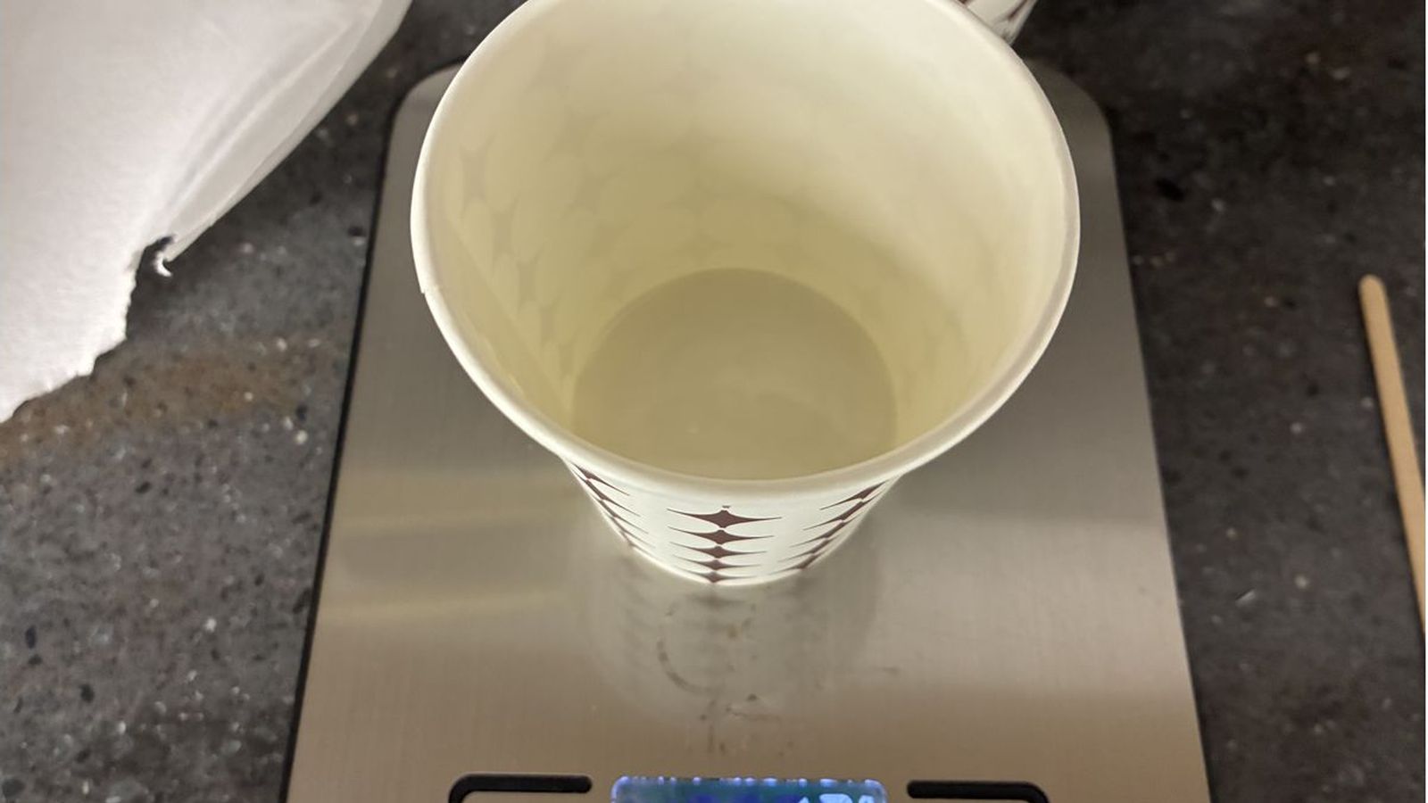
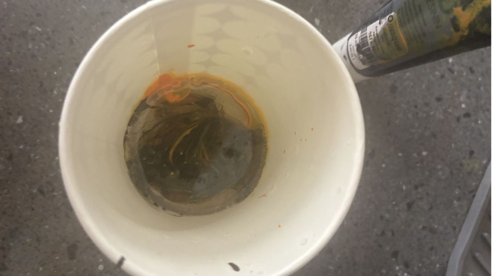
To measure the volume of my mold I filled the wax with water then transfered the water to paper cup which then ı marked the end point of the water with a marker to find volume of my wax engraving.
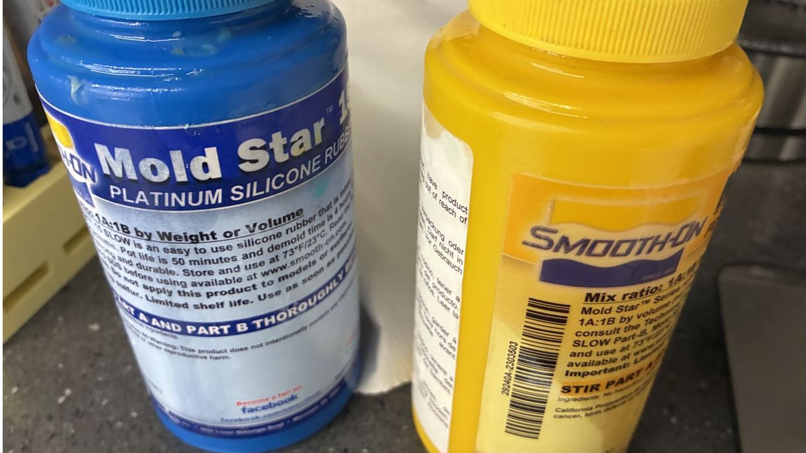
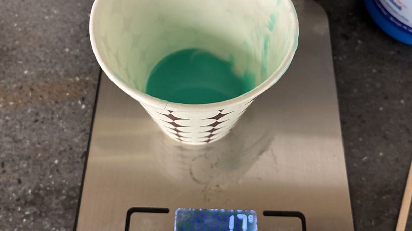
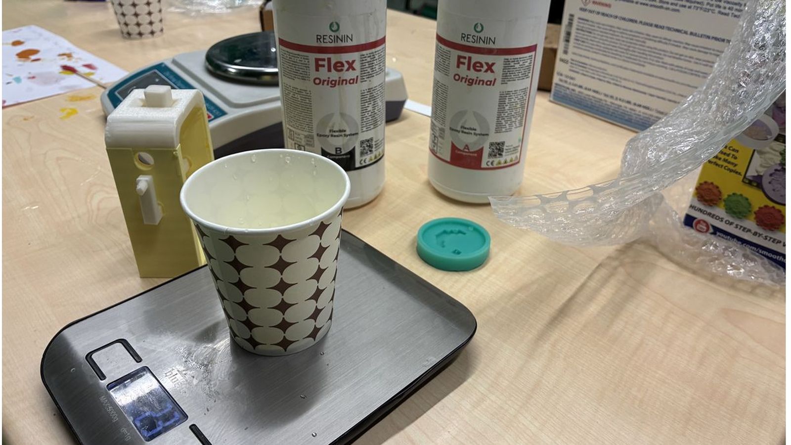
 Then using a scale I mixed 1 part A and 1 Part B molding silicone by weight as instructed to match the volume that I have found previously.
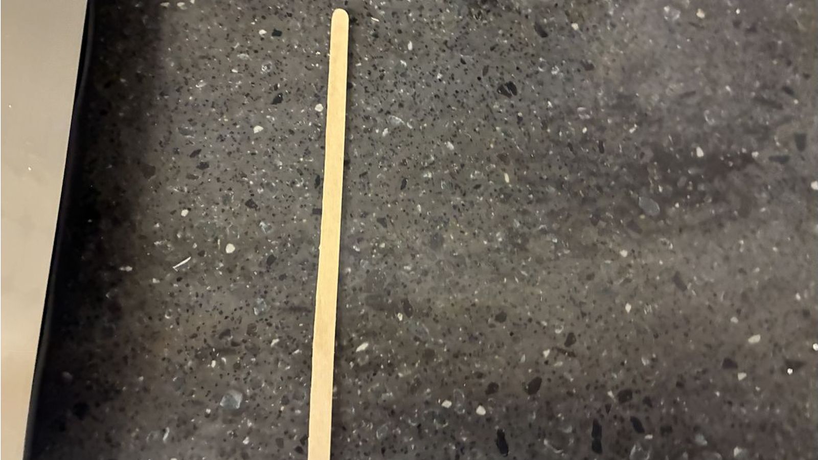
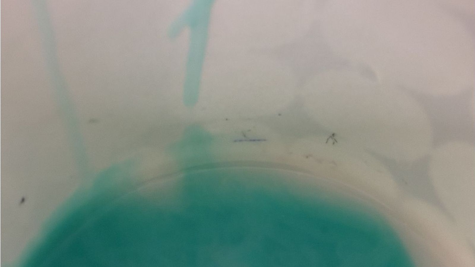 Then I mixed the solution throughly using a disposable wooden mixer. and poured it slowly to not introduce air bubbles and tapped the wax to the table a couple of times to pop the ones on the surface
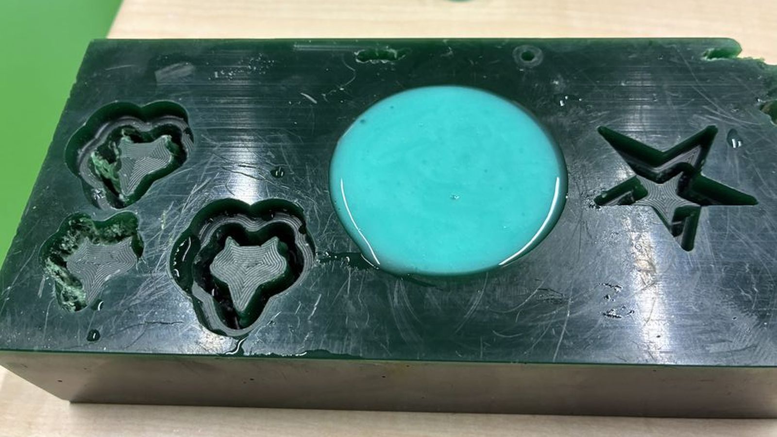 Then I waited over night(Since it was late and went home)
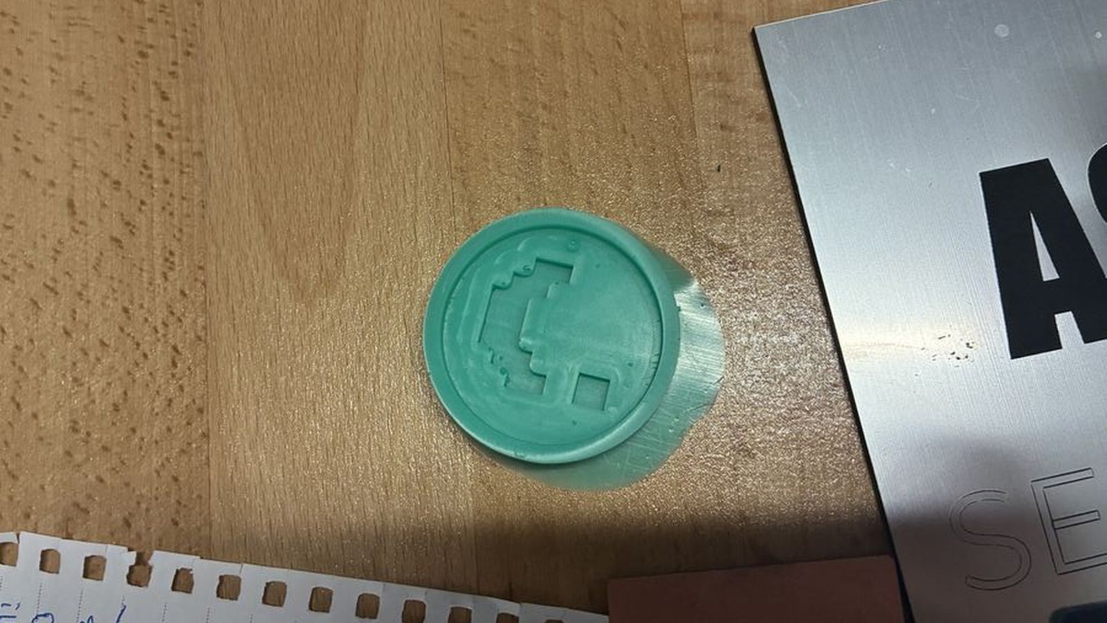
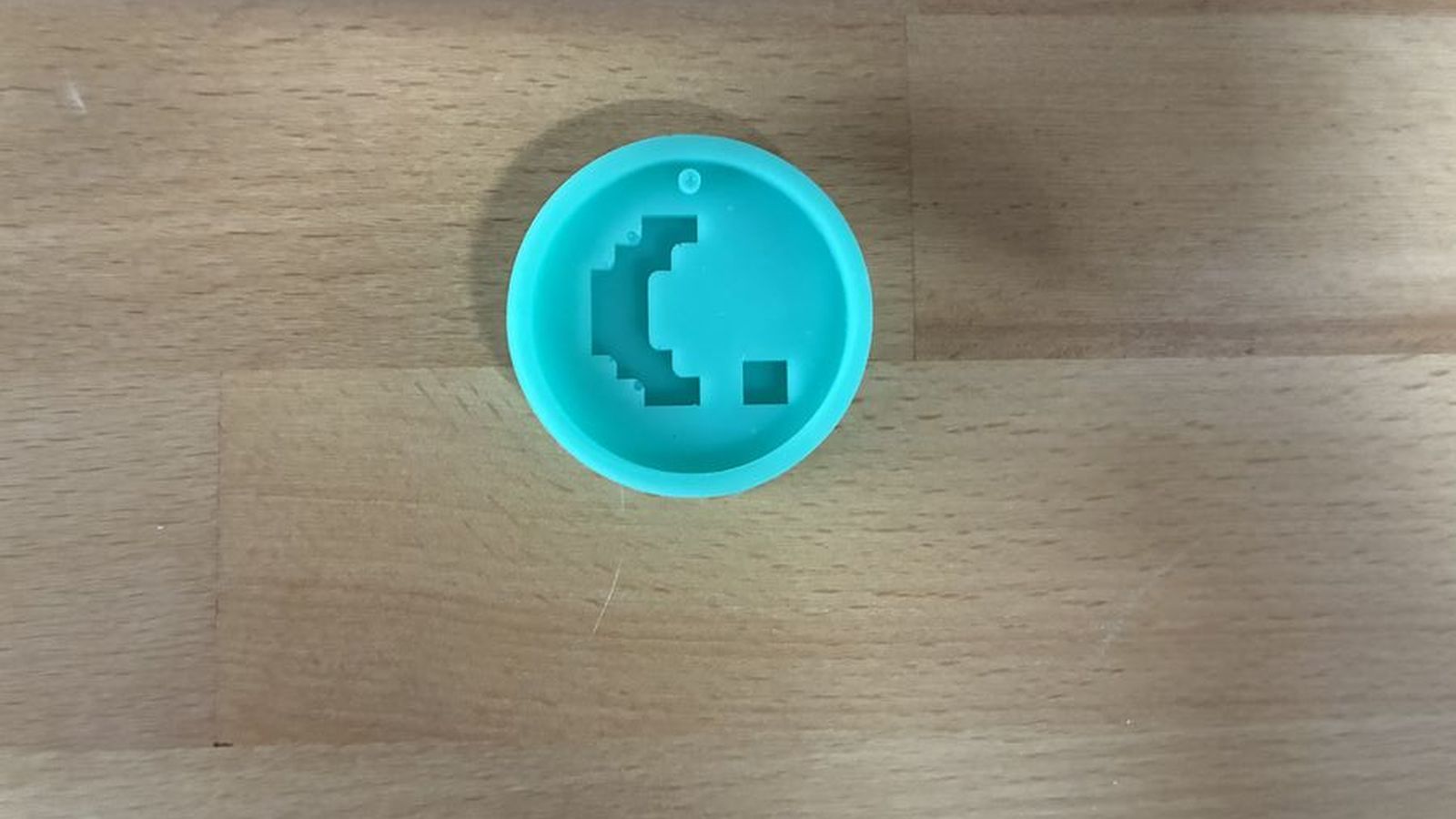 This is how it looked after some clean up
Casting
For casting I used the exact same procsses as the mold but used resin instead of mold silicone this resin also is a two part resin which has an instrection to fix the Parts A and B equaly.
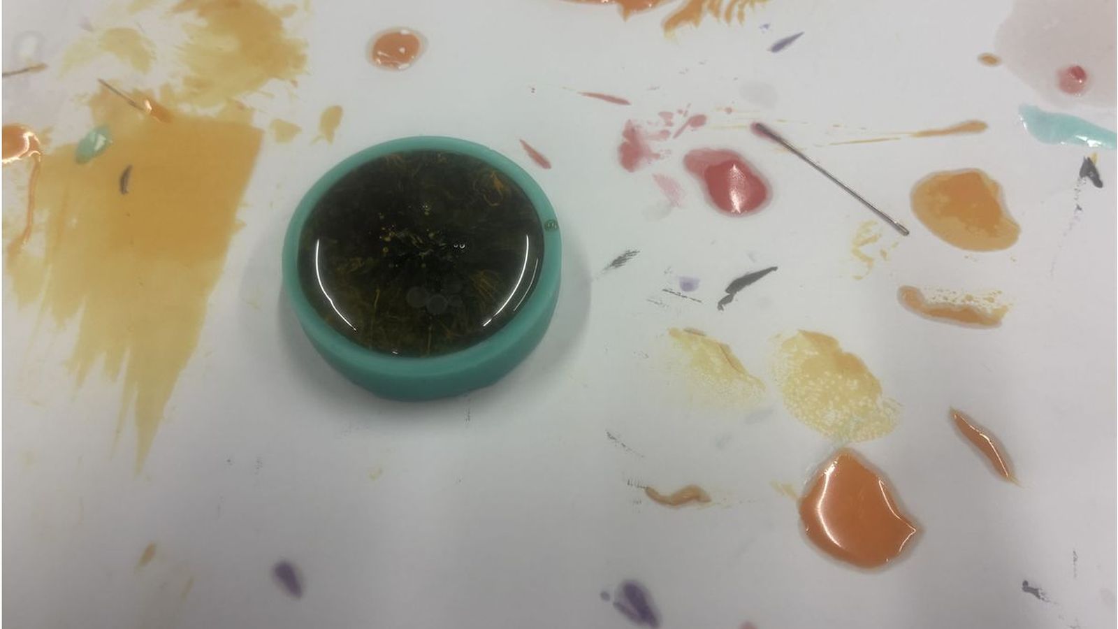
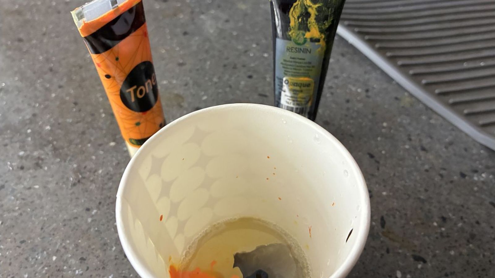 After mixing the resin I added black and orange coloring
 And rather then mixing the colors I just poked it with the wooden mixer to achive and insteresting pattern
 I then filled the mold with the resin mixtured and waited for about 5 hours for it to set
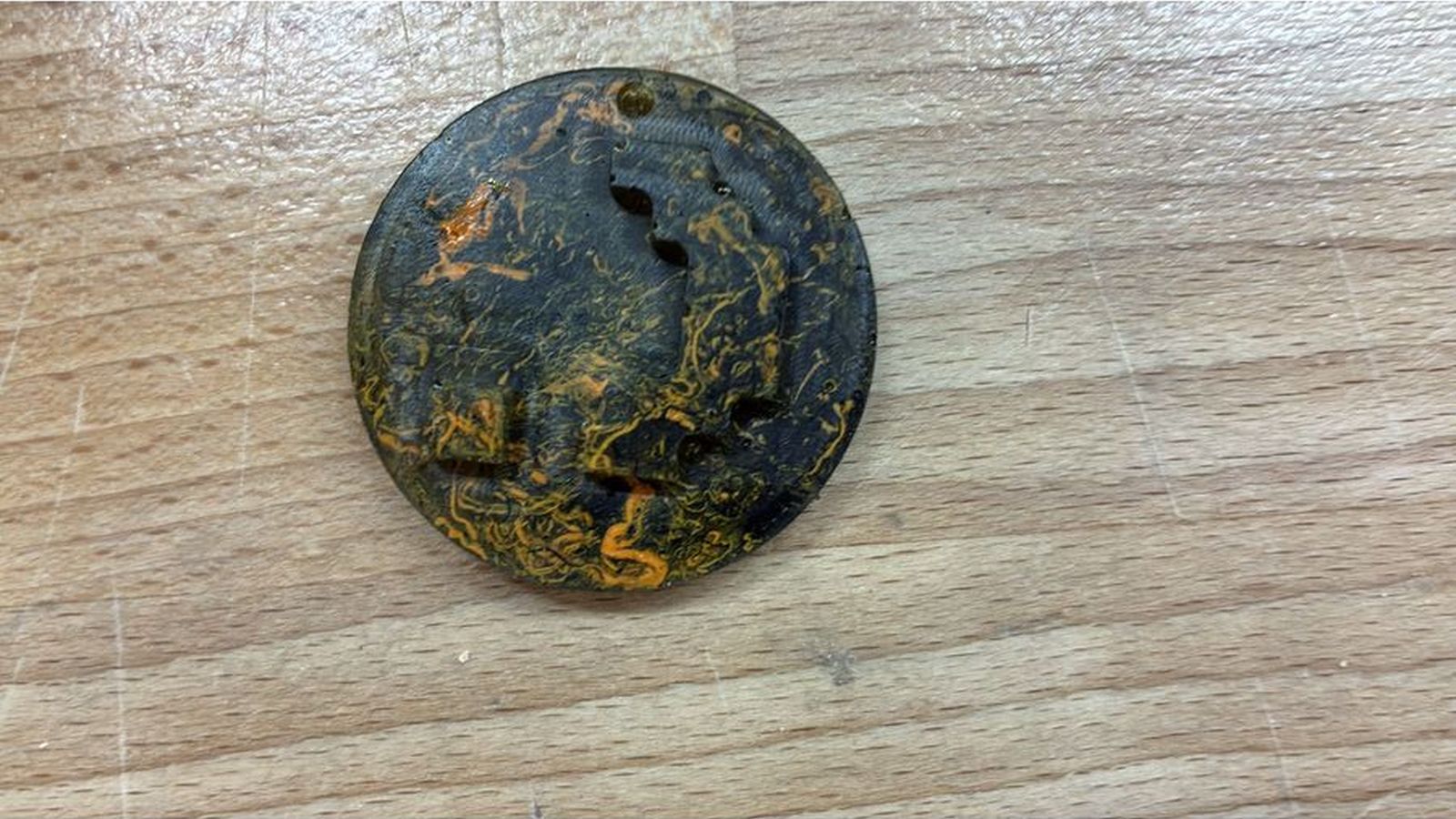 This is how the final cast looks like