Assignment
Group assignment:
- measure the power consumption of an output device
Here is the link to the group assignment
Individual assignment:
- add an output device to a microcontroller board you’ve designed, and program it to do something
Servos
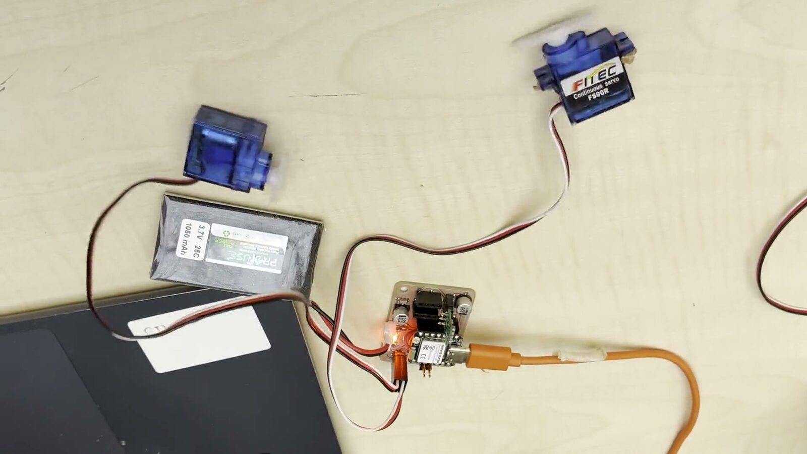
For this week’s assignment I will be commanding 2 servos simultaneously as an output device. I will be using the same board that I produced in my electronics production week and also modifying the code there to run the servos. I am using FS90R contunuis servos from Feetech
Code
Here is the code:
#include <ESP32Servo.h>

Servo servo1;
Servo servo2;

int servoPin1 = 17;
int servoPin2 = 19;

#if defined(CONFIG_IDF_TARGET_ESP32S2) || defined(CONFIG_IDF_TARGET_ESP32S3)
int potPin = 10;
#elif defined(CONFIG_IDF_TARGET_ESP32C3)
int potPin = 4;
#else
int potPin = 34;
#endif

int ADC_Max = 4096;
int val;
int angle;

void setup() {
  ESP32PWM::allocateTimer(0);
  ESP32PWM::allocateTimer(1);
  ESP32PWM::allocateTimer(2);
  ESP32PWM::allocateTimer(3);

  servo1.setPeriodHertz(50);
  servo2.setPeriodHertz(50);
  servo1.attach(servoPin1, 500, 2400);
  servo2.attach(servoPin2, 500, 2400);
}

void loop() {
  val   = analogRead(potPin);
  angle = map(val, 0, ADC_Max, 0, 180);

  servo1.write(angle);
  servo2.write(angle);

  delay(200);
}
So this code uses PWM signals to run 2 contunius servo motors attached to the 17-19 GPIO pins using PWM it uses the ESP32Servo Library which I downloaded from the arduino library manager. And uses the Knob Example sketch included in the ESP32Servo Library as its base which I also used to test my pcb in the electronics production week
Result
Here is a video of them working
I learned how to use GPIO pins to command output deviece. What PWM is and how use it to run continous servos.