PCB - Cube3D MxPro
After I was done designing my pcb board in Kicad I exported the gbr files. There are two software programmes used in this progress, Cube 3D Cam Pro and UUCNC.
Cube 3D Cam Pro:
I opened up my files and selected the right layers.
- Top: for engraving (F-cu.gbr, gtl)
- Mechanical: for edge cuts (Edge_Cuts.gbr, gko)
After this I generated the g-codes
UUCNC:
- I started out by putting the blade and twisting it with wrenches
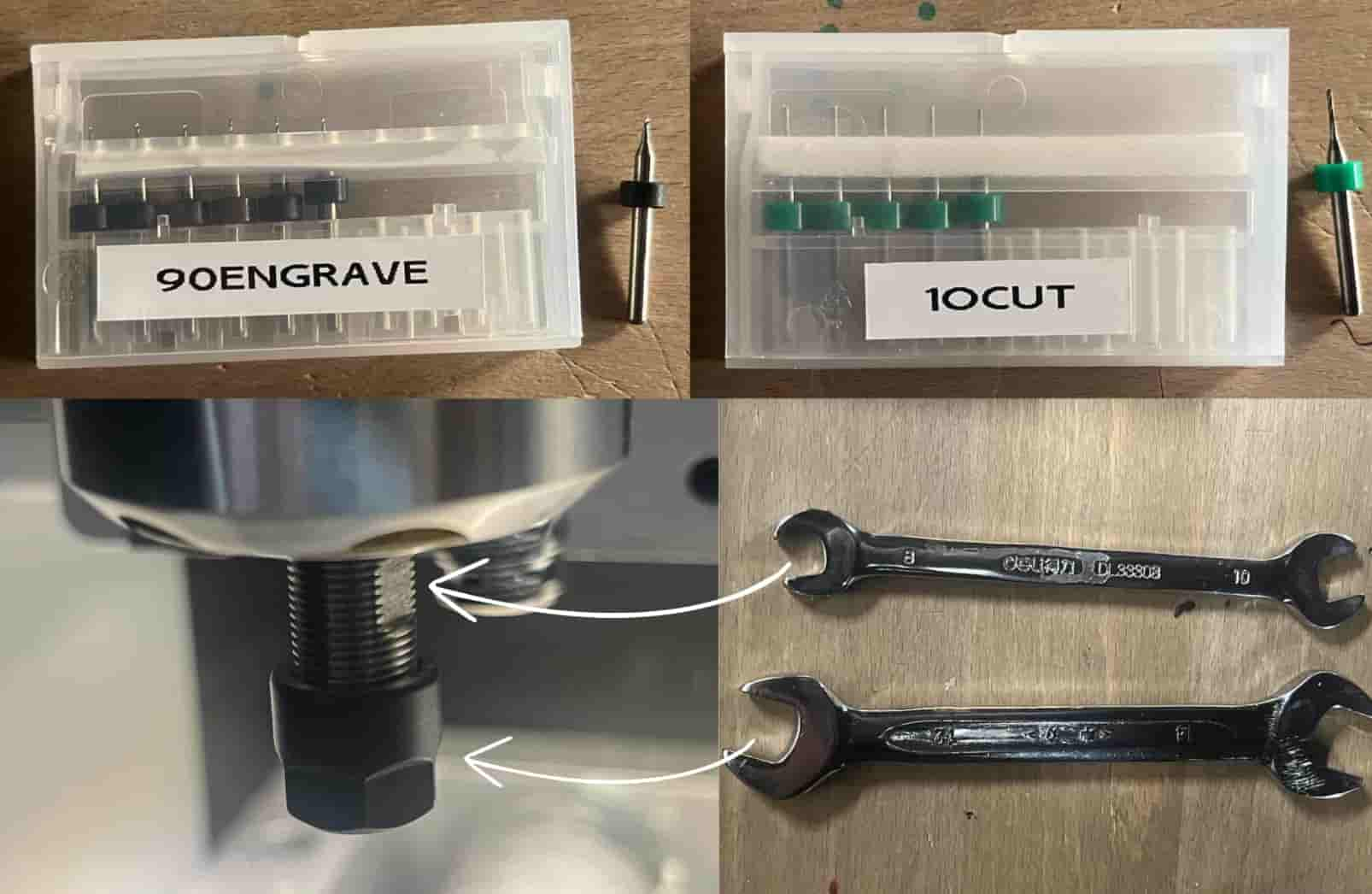
- I set up the coordinates with reset > home all > go to park 2 > zero all (for x and y coordinates)
- Probe testing to set z coordinates to 0
- Exported the g code of the engraving file first and then the edge cut file. I changed the blade in between
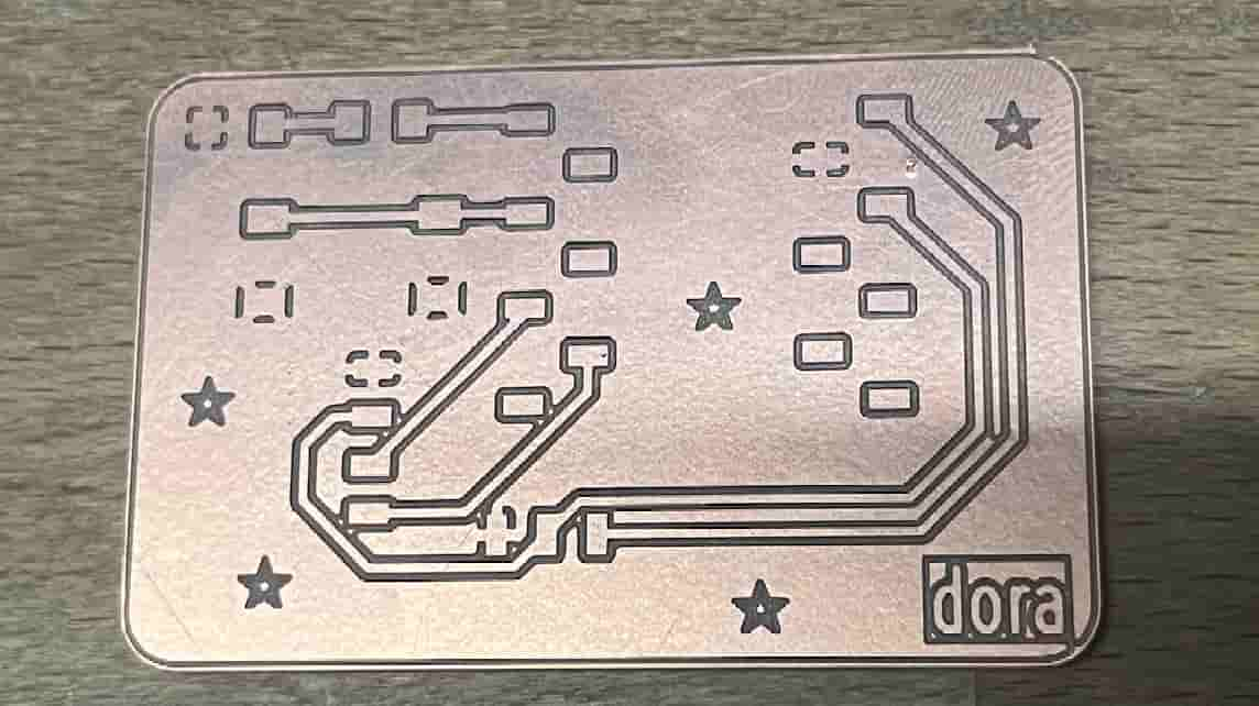
Here is the board of my first design:

I edited the track widths after this print since they came out too thin
Setting up the board
The componenets I chose were:
- seeed studio xiao esp32c3
- LED 1206 with the Cathode (+) connected to GPIO2 and Anode (-) connected to GND
- Resistor 1206 between LED and GPIO
- Switch Tactile spst-no 0.05A 24V
- conn header 4pos 0.1 tin smd
- conn header 3pos 0.1 tin smd
- conn header 5pos 0.1 tin smd
I cut and combined the conn headers to make them fit my board
Multimeter
I used a mutltimeter very frequently. You can use a multimeter to check if everything on the board works properly.
Tracks that are connected and are supposed to have a flow of electricity beep when theyre touched
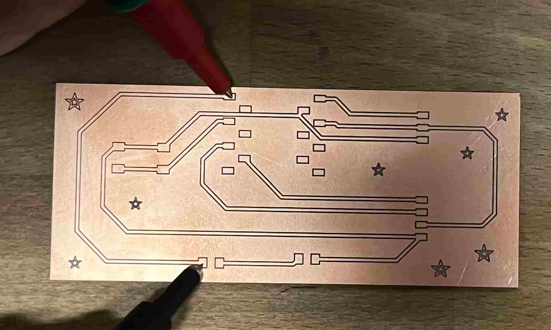
With the same logic, tracks that arent supposed to connect beep if a component is soldered wrong and the melted wire gets on the board, connecting them. I had this fail many times
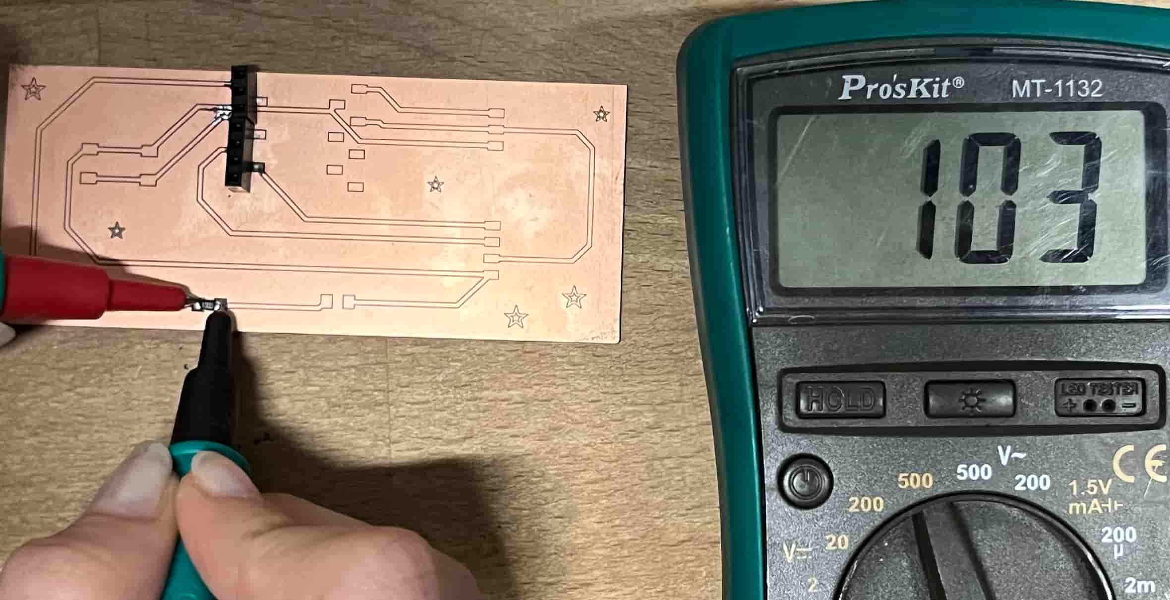
I also tested my resistor. Resistors dont make it beep if theyre working but they show the resistance value on the screen. Here is a soldered 100ohm resistor
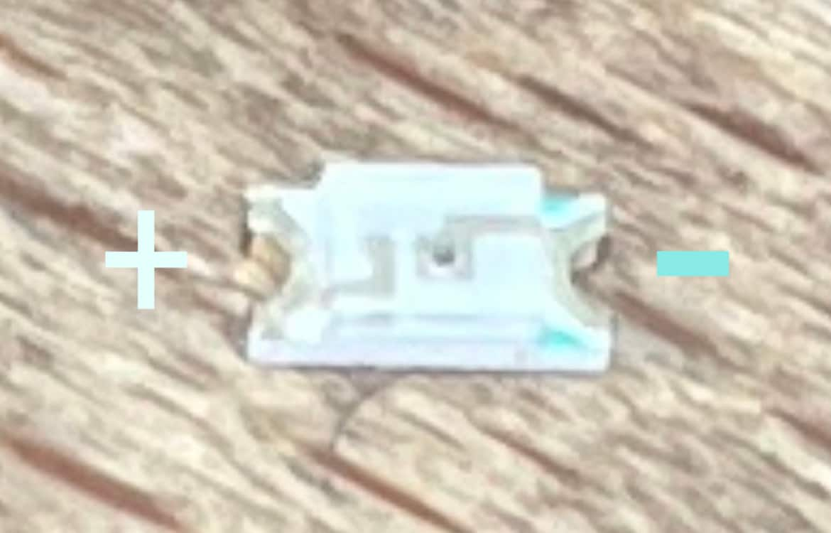
I couldnt figure out which side of the LED was (+) and (-) so I used a multimeter. I chose the LED testing option.

I touched both sides at the same time with the pins to see when it would light up. It lit up when the black part was on the green side of the led and the red on the other.
LED SMD:
Soldering
Board 1
This is the board where I did direct GND Connection to ESP32C3.
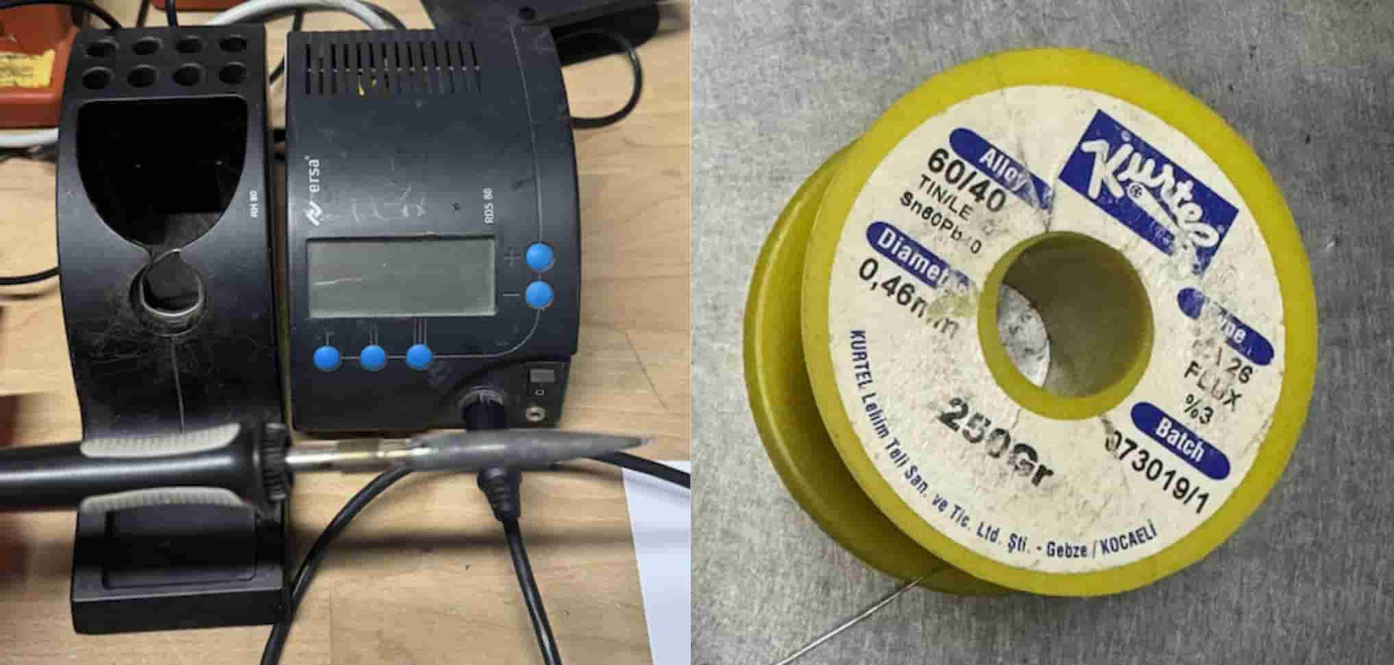
After figuring the LED out I was ready to start soldering. Here is the soldering setup.
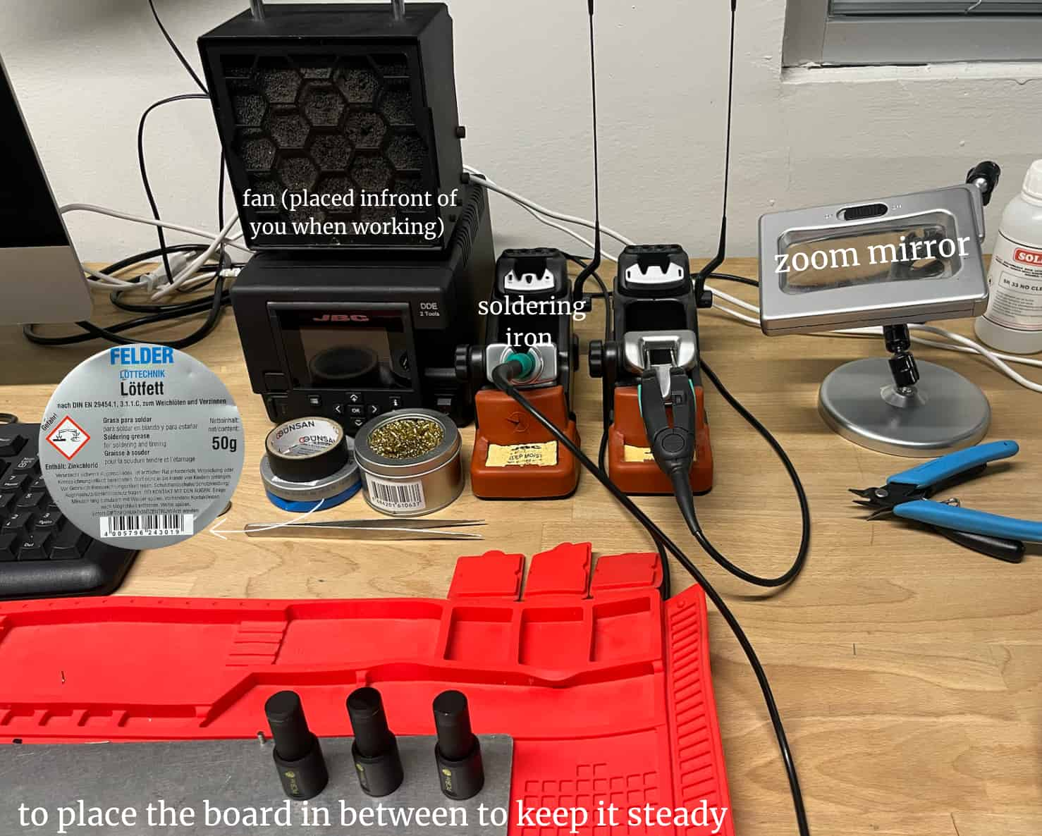
Soldering Paste: The image I pointed out is soldering paste. I used soldering paste to help hold the smaller components in place. I put some on the board where I would be placing the led and resistor components and then soldered them.
Soldering iron tip cleaner: Next to the soldering paste there is the cleaner, sunline SL-08C. I put the tip in this cleaner after using it.
Soldering process: The soldering iron heats up very fast in just a few seconds after you grab it. After placing a component I placed the soldering iron on on side and then brought the wire next to it so it would melt and stick.
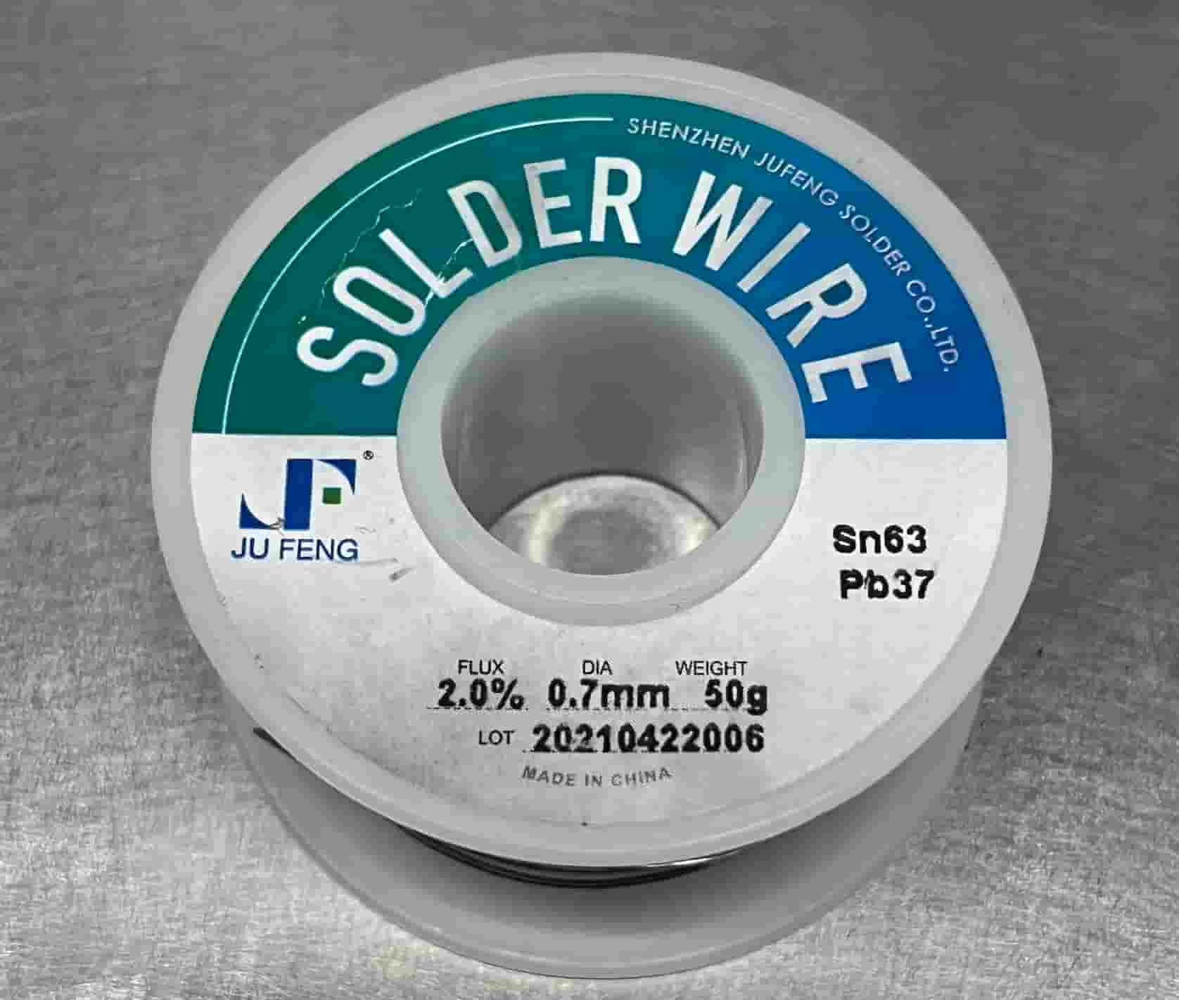
Here is the soldering wire I used:
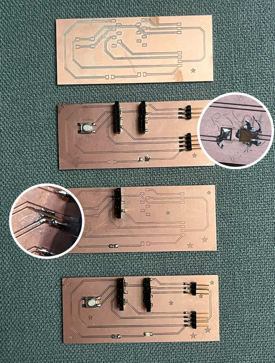
Here are the boards after soldering (all fails) :
Board 2
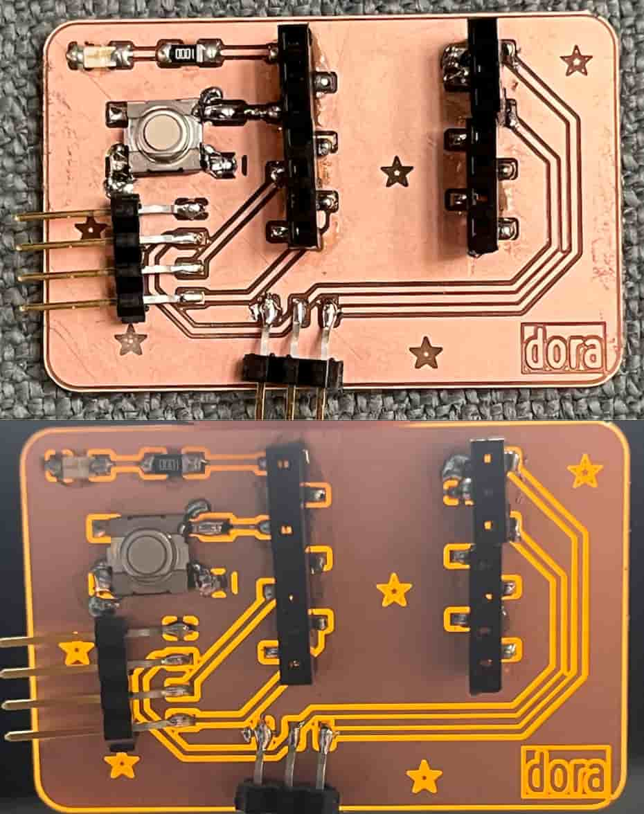
This is the board where I used a Ground Plane as GND. Here is the board:
Here is the board after soldering:
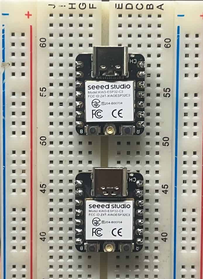
esp32c3
I then soldered the esp32c3 onto the 7-pin male header:
The one on the top is my second attempt. I used a different soldering iron and wire (a thinner one):
Programming
Here is the code I wrote. The led turns on when the button is pressed
|
|
Here is the board:
Group Assignment
You can check our group assignment here