Fusion 360
I started out by drawing a star. I used fillet to make the edges softer.
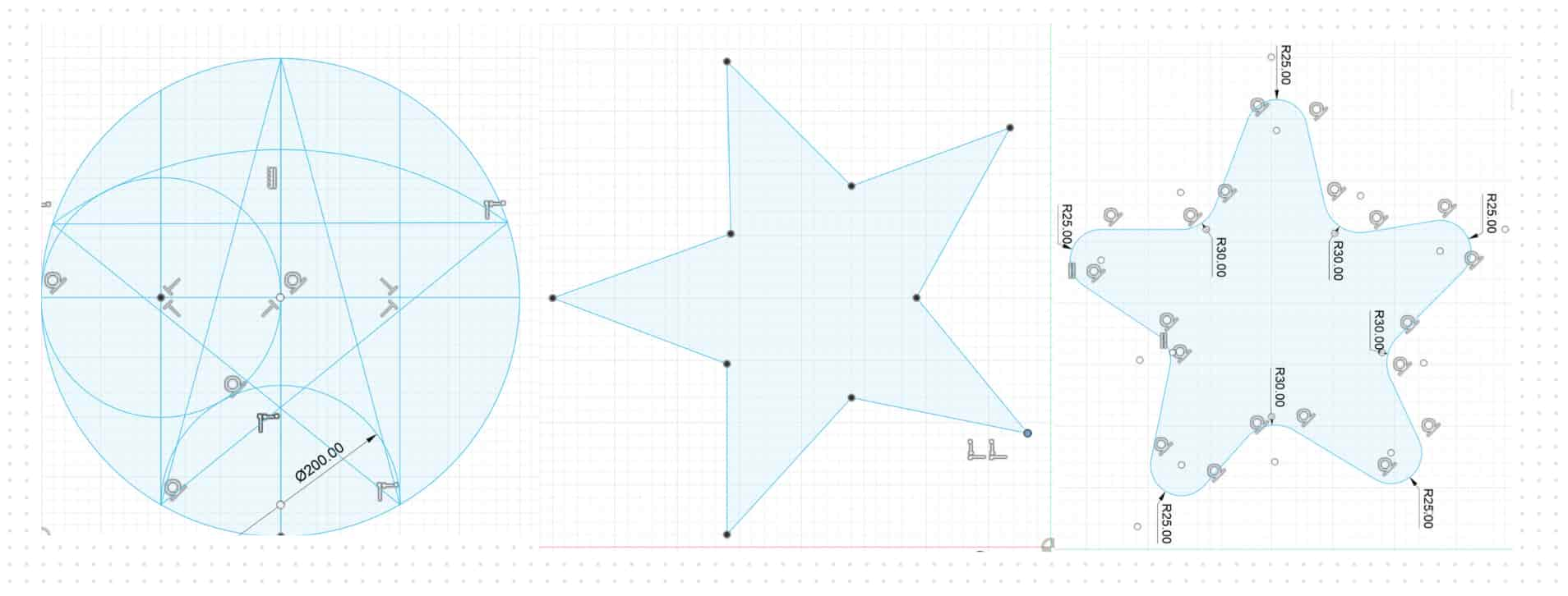
I used a tolerance of 3mm so the parts would fir into eachother. Here are the measurements:
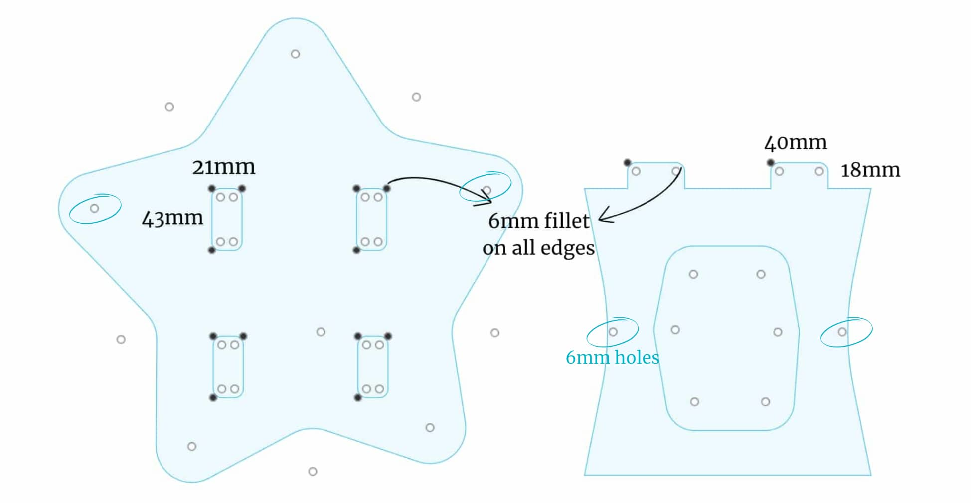
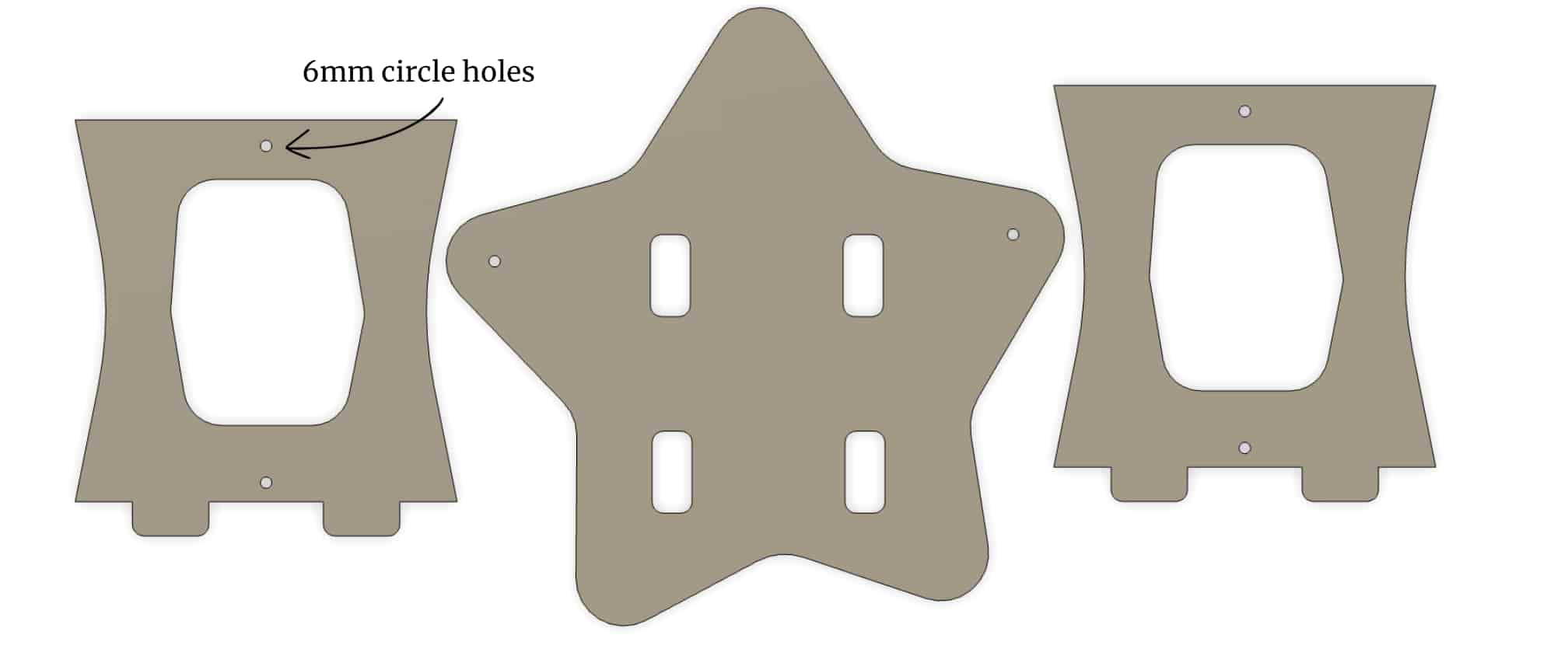
I drew 6mm (depends on blade) circle holes and extruded by 18mm (length of the wood)
Toolpath Generation
This step is to define the cutting paths the CNC machine will follow.
Arrangement
These holes are to put screws in before the cutting process begins. Without the screws the pieces would move after being cut so we need screws.
Creating Arrangement: Creating an arragment from the bodies help create the optimal cutting positions
- First we need to make the bodies into components: Right click Bodies folder > Create Components from Bodies
- Modify > Arrange > Select Components
- Envelopes > Select Plane. Here are the settings:
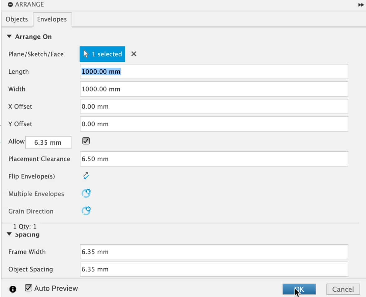
The wood pieces are 1 m so I chose 1000mmx1000mm for length and width
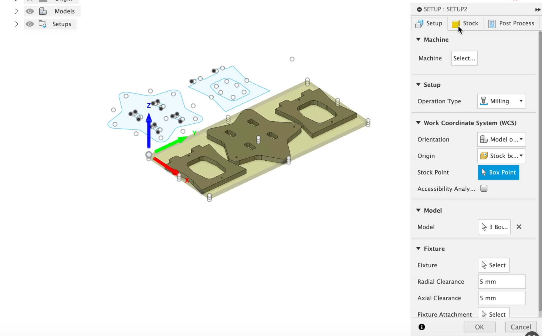
Manifecture > Setup
After arrangement is done we go to:
- Manifecture > Set Up
- Select the models
- Stock > Stock Top Offset = 0
- Stock Point: Choose the corner
Drilling > Coolant = Disabled Drilling > Tool > Select > choose the following blade:

Drill for the holes
Geometry (3rd in Drill) > Selection Mode = Selected faces (select the 6mm holes), Minimum Diameter = 1
Click OK > Creates Setup called [T2] Drill1 [Rapid cutout]
2D Countour - Outline
- 2D > 2D contour > Counter selection > Select the bottom outline of the objects
- Spindle Speed = 1800 rpm
- Cutting Feedrate = 800 mm/min
Click OK > Creates [T1] 2D Contour 1
2D Countour - Inside Cutouts
- 2D > 2D contour > Counter selection > Select the bottom outline of the inner cuts:
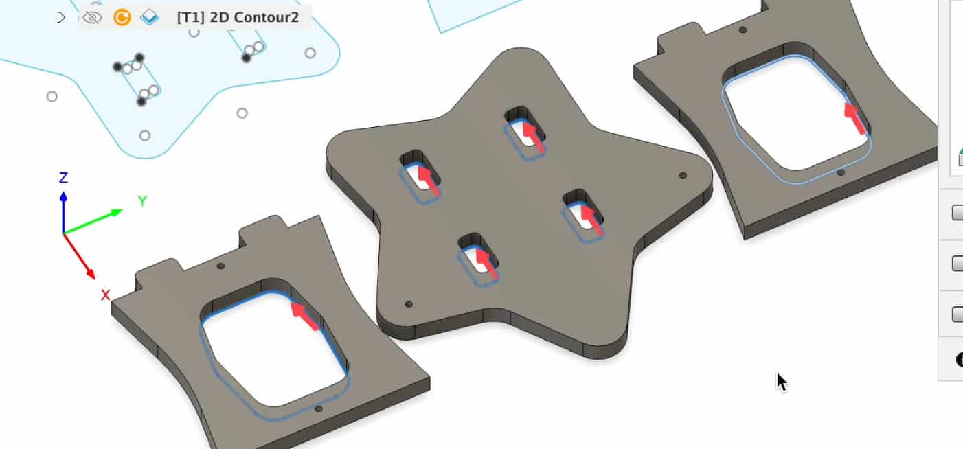
- Same Settings
Click OK > Creates [T1] 2D Contour 2
Simulate and Create
To see the simulation of the cutting process: Right Click setup folder > Simulate
Right Click setup folder > Create NC program > Click Post
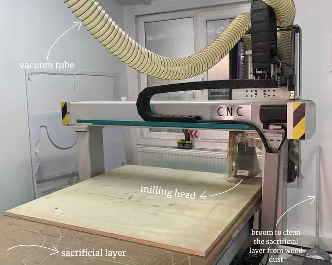
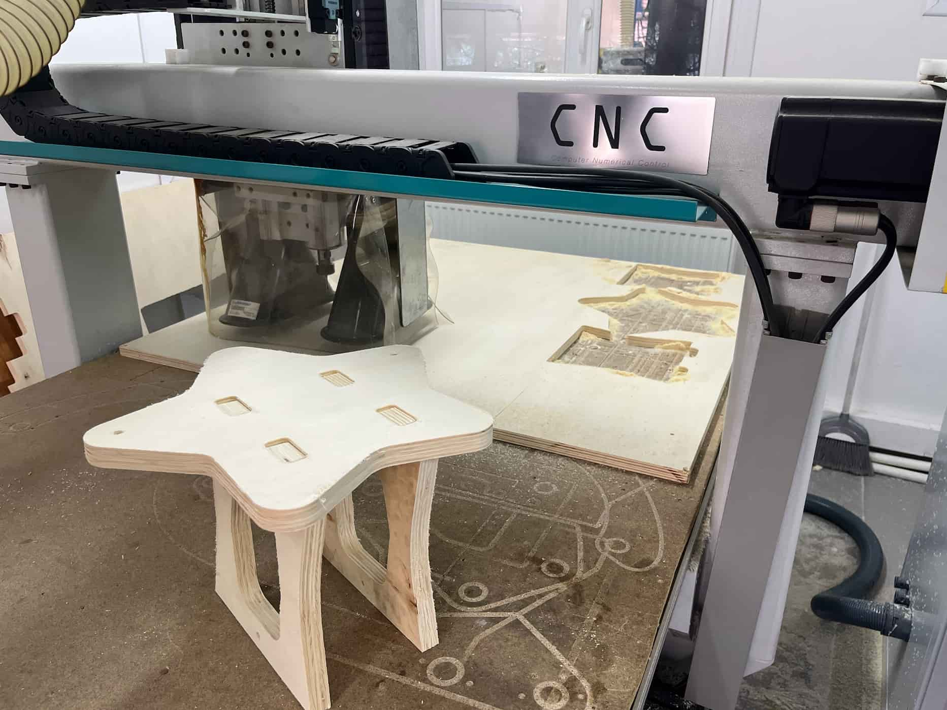
CNC
A CNC is a computer-controlled manufacturing tool used to perform precise machining operations like cutting, drilling and milling. It uses G-Code to determine where to move. It moves in x, y and z directions. Here is the CNC machine:
I put the file I generated into a USB and then connected it to the computer for the CNC.
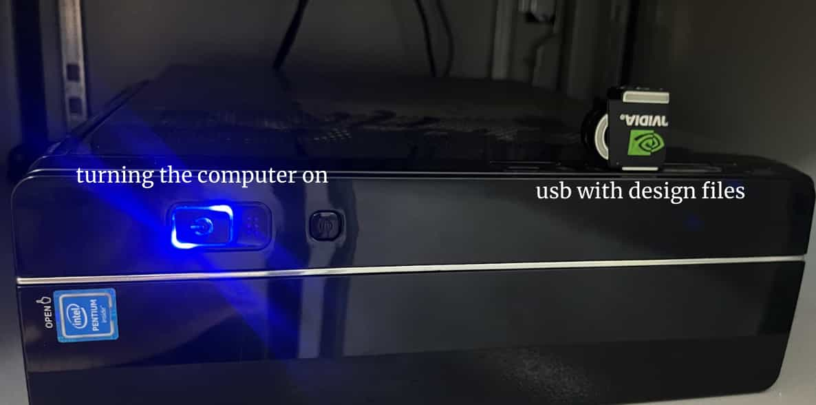
Here is what the software for the CNC looks like:
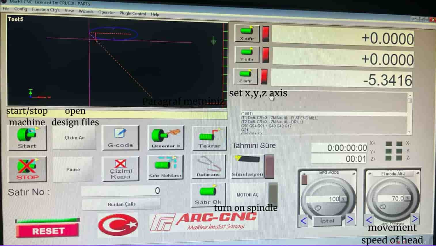
Steps for using it:
- Click Reset and press the physical emergency button The arrows on the keyboard move the head in x y directions and a,s moves z direction (a is up s is down)
- Move the head and click zero x and y
- We need to slow down the movement while setting the z direction so the blade doesnt go down too fast. I changed the setting of the mode on the right bottom corner to around 5%
- Turn on spindle. This starts spinning the blade. I lowered it untill it was touching the wood just a little like the image below:
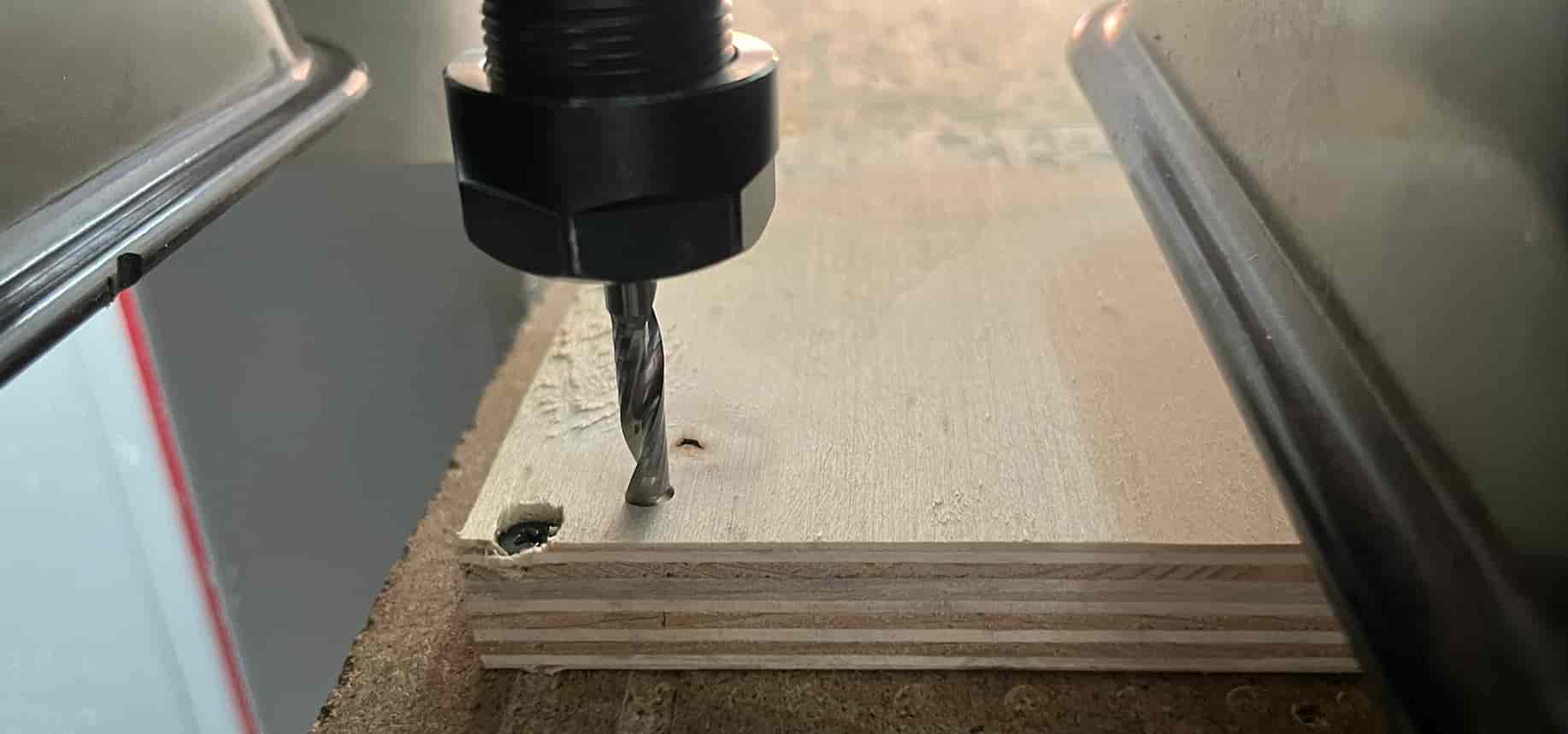
- Click zero z
- Drag the head back up so that it doesnt cut throught the wood when it starts moving to drill and cut
- Import File
- Start
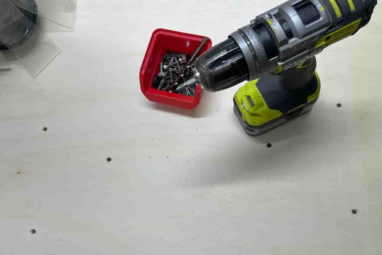
The first thing that happens is drilling so you can put the screws in before cutting begins.
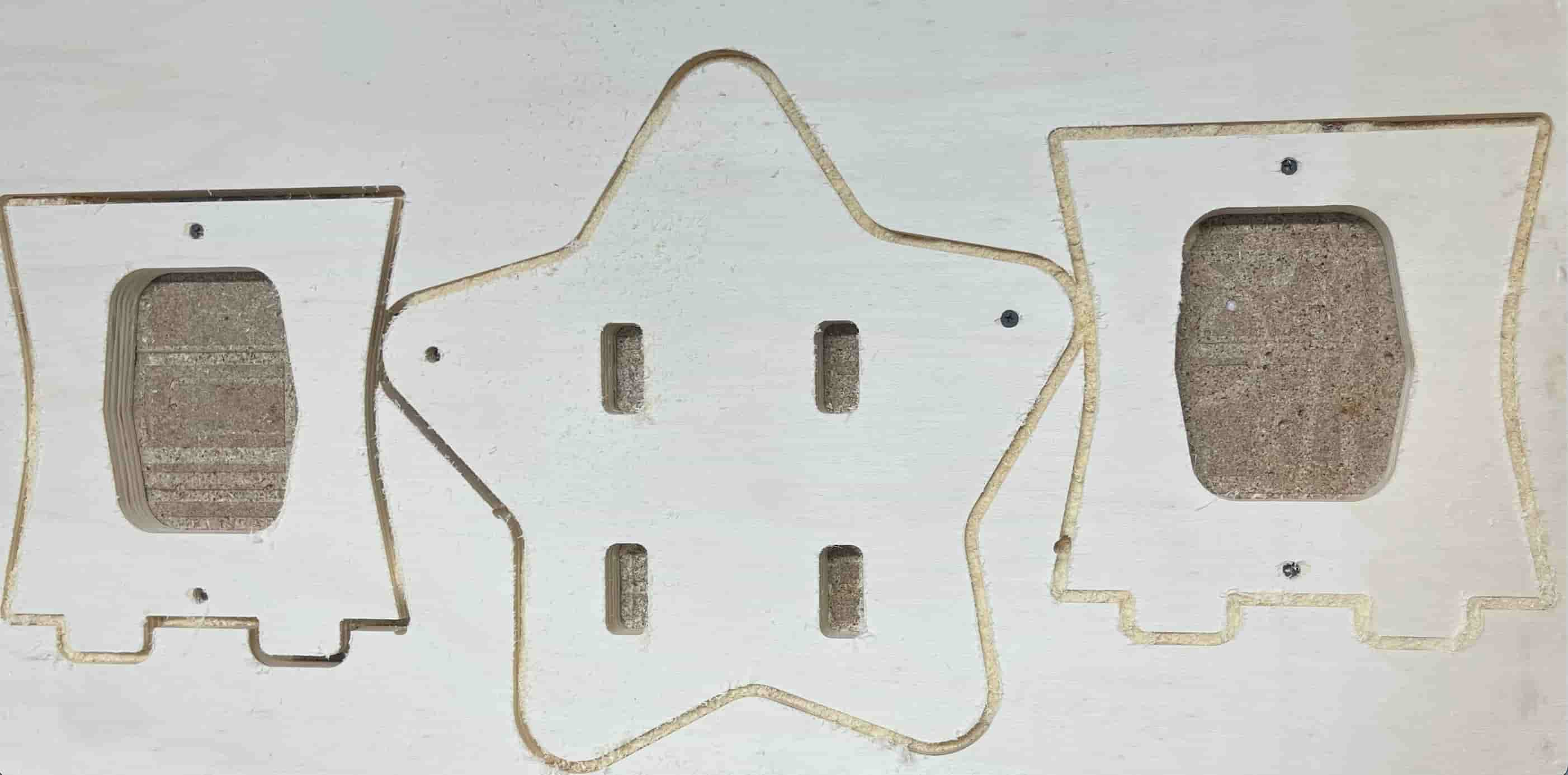
The pieces cut out:
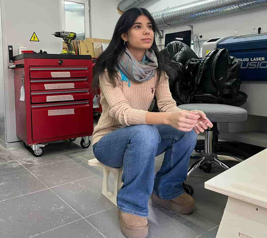
The table put together:
Me sitting on it:
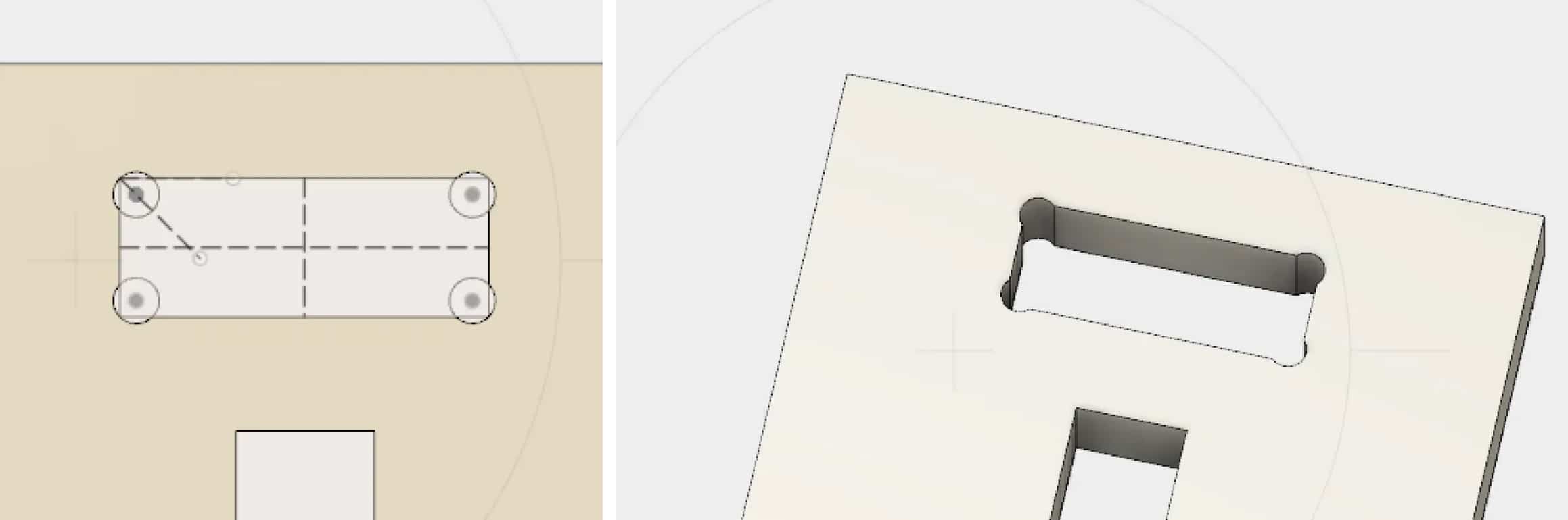
Dog Bone Fillets
I needed to use extra force (pushing on the legs to make it fit into the holes on the chair part) since I didnt use dog bone fillets. This made press-fitting more difficult.
A dog bone fillet is a small round cut added to the corner of a slot so that square tabs can fit properly when using a round milling bit. This makes press-fitting much easier.
Here is an example of how the holes look before and adding dog bones taken from this website:
Conclusion
This week, I learned how to design and prepare files for CNC machining using Fusion 360, including generating toolpaths. I understood the importance of proper fit and how missing dog bone fillets can affect press-fitting and assembly.
Group Assignment
You can check our group assignment here
Files
Here is the f3d file for the star table design: file