Overview
I2C is a two wire communication protocol used to connect low speed devices like sensors, displays, etc to microcontrollers. The two wires are SDA (Serial Data) which carries data, and SCL (Serial Clock) which synchronizes data timing
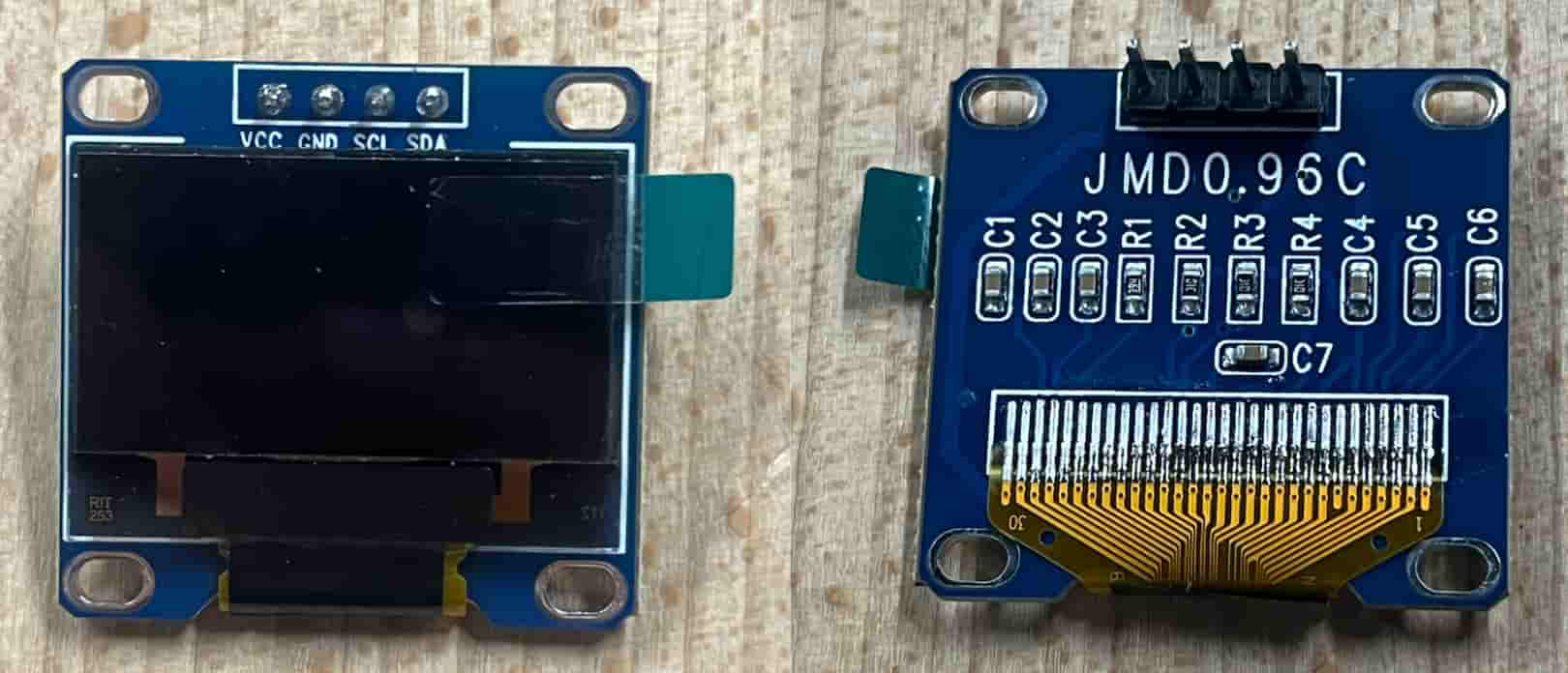
Screen JMDO96C 128x32
Here is what the screen looks like:
What to connect where:
I used the PCB I made in Electronics Production week.
VCC -> 5V
GND -> GND
SCL -> GPIO (6)
SDA -> GPIO (7)
Arduino
Problem
I was having a problem with getting the screen to work.
- First I tried the example code from adafruit and tried to debug with serial. I tried both 128x62 and 128x64 to make sure the issue wasn’t picking the wrong screen size.
- Then I thought it may be a problem with the screen itself and tried a different one. Still Didn’t work.
- Finally I grabbed a multimeter to see if there was anything wrong with the connectivity of my PCB, and there was. One pin of one of the conn headers was slightly raised. I had never used the other GPIO pin before so I hadn’t realized it was not working and causing problems with connectivity. I pressed down with soldering iron slightly and then the issue was fixed, the screen worked with the example code.
Example Code
I installed Adafruit SSD1306 by Adafruit in Arduino and selected board from Tools > Board and made sure I was on the right port which is dev/c.usbmodem1011. I then tried the example code from File > Examples > Adafruit SSD1306 > ssd1306__128x32_i2c
Custom Code
I then tried out my own design. To do this I used this website to resize the image and img2cpp to convert the image to code
Here is the code file.
Group Assignment
You can check our group assignment here