Overview
Output devices are devices that carry out actions based on commands (ex: from a computer). They receive signals and turn them into physical outputs (ex: movement, light).
Servo SG90
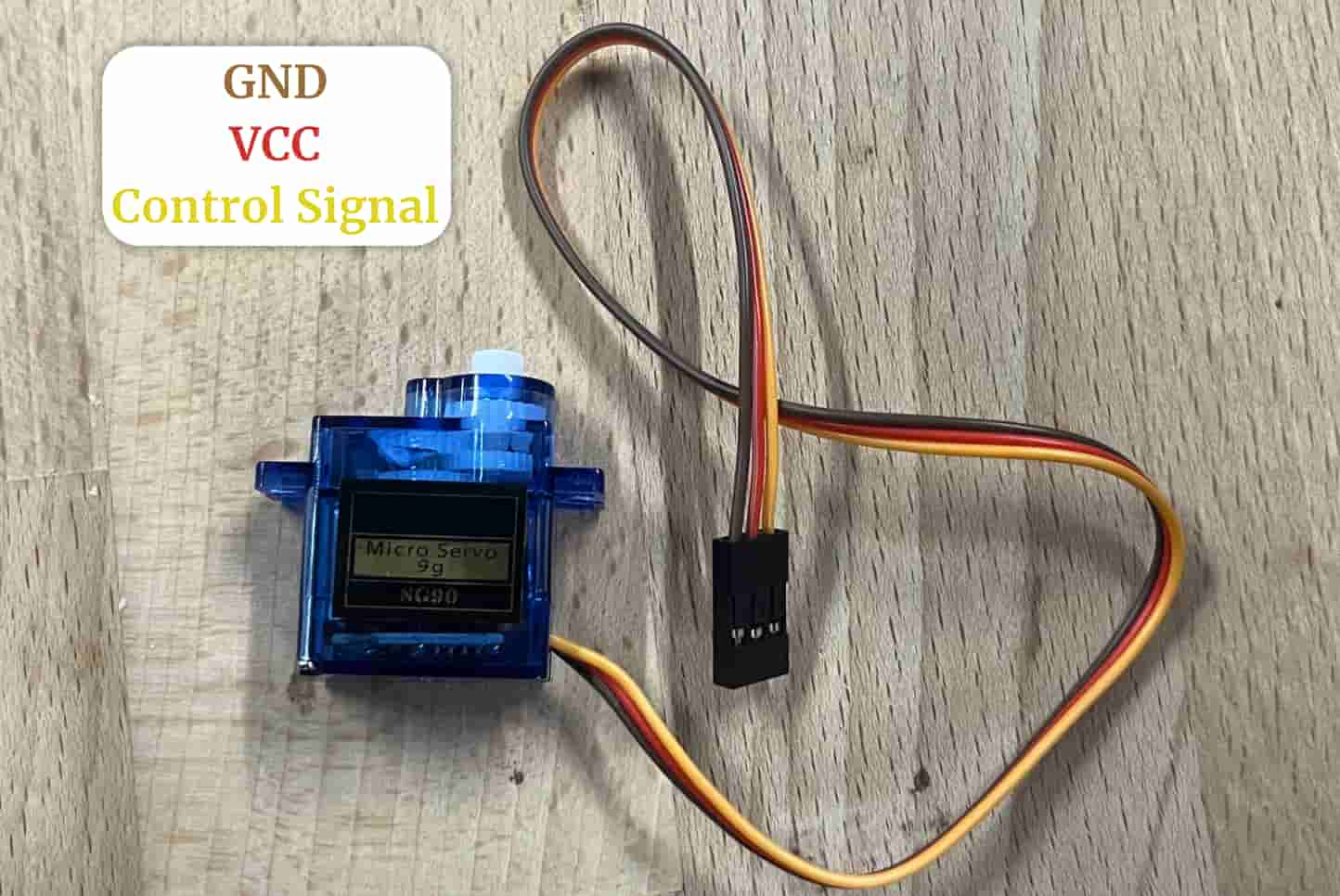
Servo motors spin to certain angles, you can control their angle(with PWM signals) and speed(with delay functions). The servo I am using only moves 0-180 degrees. I connected a Servo SG90 to the pcb i made in Week 8
Here is the Servo:
PWM
PWM signals work by sending ON and OFF signals very very quickly. The the switching between the two states is what determines the output’s strongness (ex: brightness for light, speed for movement).
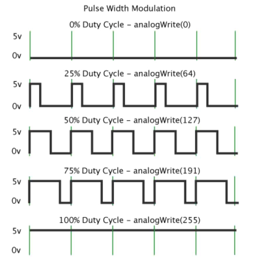
For example when we record a video of a light source with phones (our eyes cant detect the pwm flicker, the brightness seems steady) we can see the light flickering very very fast. This is what creates the light and the flickering is what determines the brightness. The longer the ON cycle (also called duty cycle, duty cycle tells us how long the ON cycle stays on during one pwm cycle) is, the brighter the light source appears.
Similary, servo motor uses pwm to control position. Servo motors work with PWM signals (which i will be sending from Arduino).
- 1ms pulse -> ~0°
- 1.5ms pulse -> ~90°
- 2ms pulse -> ~180°
What to connect where:
Control Signal -> GPIO6 (yellow wire)
VCC -> 3V3 (red wire)
GND -> GND (brown wire)
Code
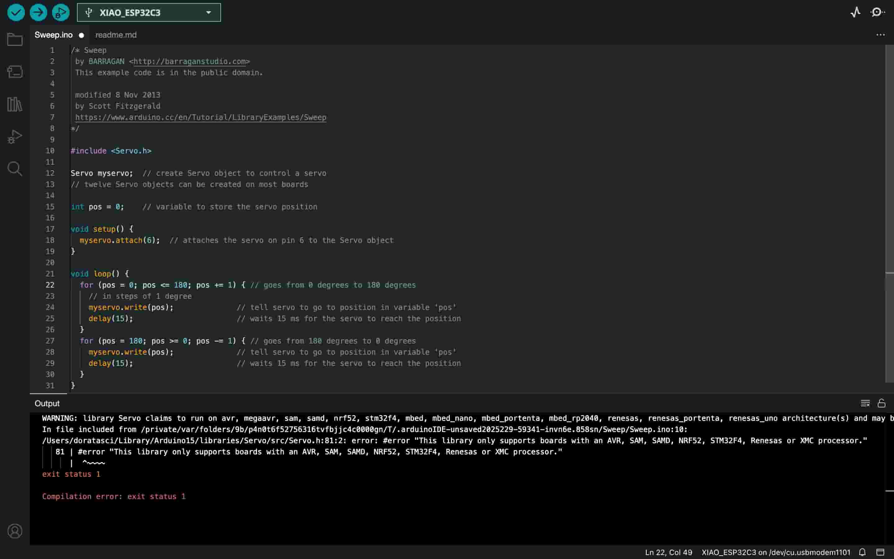
Error
I first tried the public code through File->Examples->Servo->Sweep but it gave an error:
Success
So I installed ESP32Servo by Kevin Harrington, John K. Bennett and checked the library description. The only changes I had to make after was under setup()
Spin code:
|
|
Video:
Group Assignment
Here is the group assignment