Main Idea
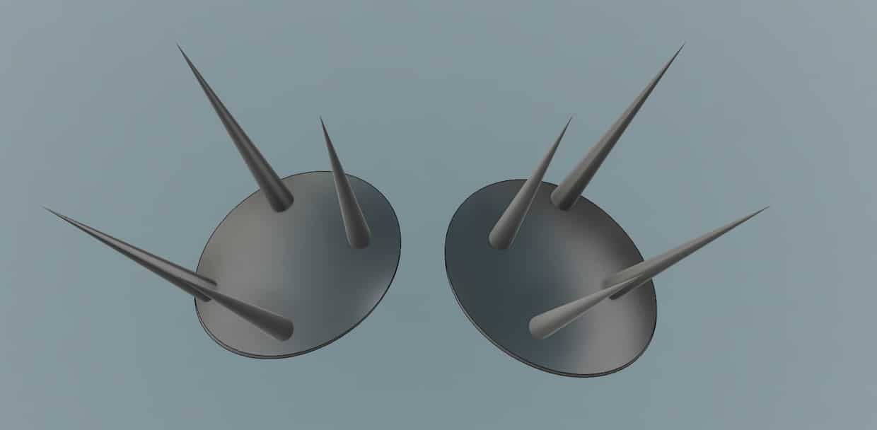
My idea was to create a timer shaped like an urchin. As I mentioned in my About Me page, my inspiration for this project came from a game I’m coding, and I wanted to create a piece that visually represents the passage of time.
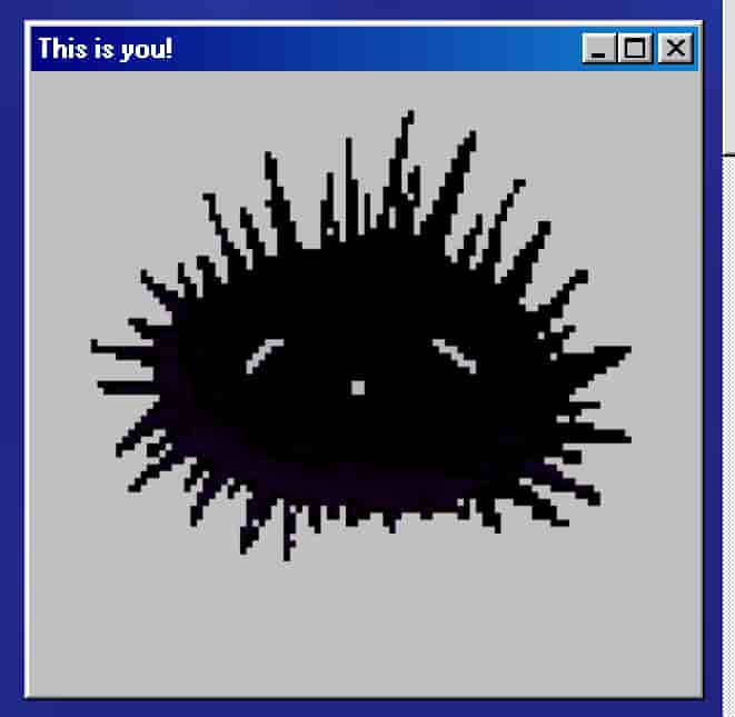
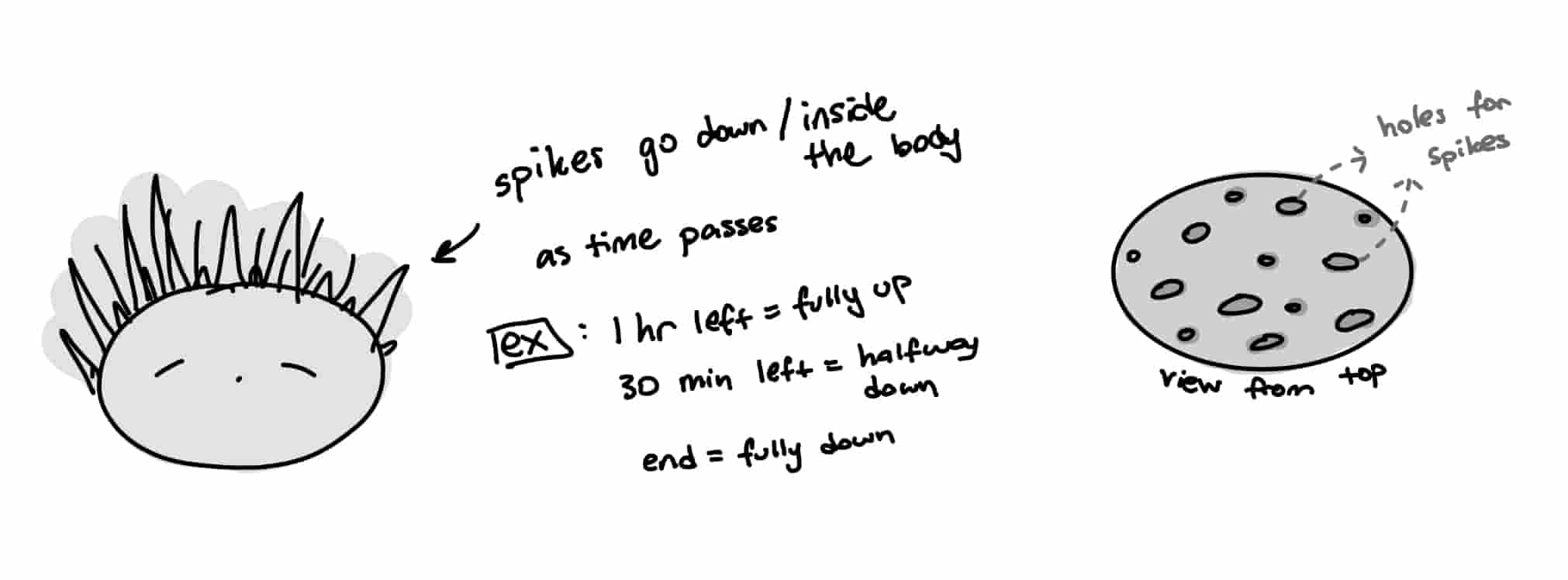
The spikes would start raised and would gradually sink, withdrawing into the urchin’s body at the end of the timer, signifying its death. But this also introduces a theme of starting over or being reborn, as the timer can be reset, and the sea urchin would have its spikes up and high once more, showing an endless cycle.
Purpose, Who Will Use it?
I wanted to create something that would show the passage of time, similar to the feeling of staring at a candle slowly burning and melting away - something you can stare at and observe time passing. I believe this would be useful for those moments when you lose track of time and need a gentle, visual reminder.
It would also be useful in every day life for things like appyling the Pomodoro Technique - A reminder of when you need to be working on a task (spikes up) and when you can rest (spikes fully down), as user is able to change the minutes.
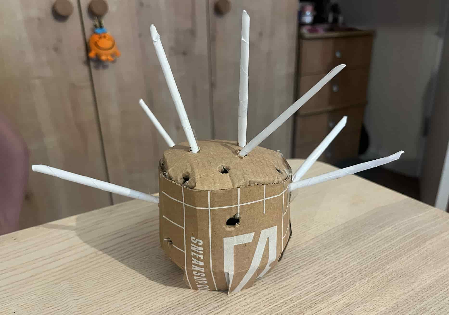
Prototype
Here is the first prototype of my final project:
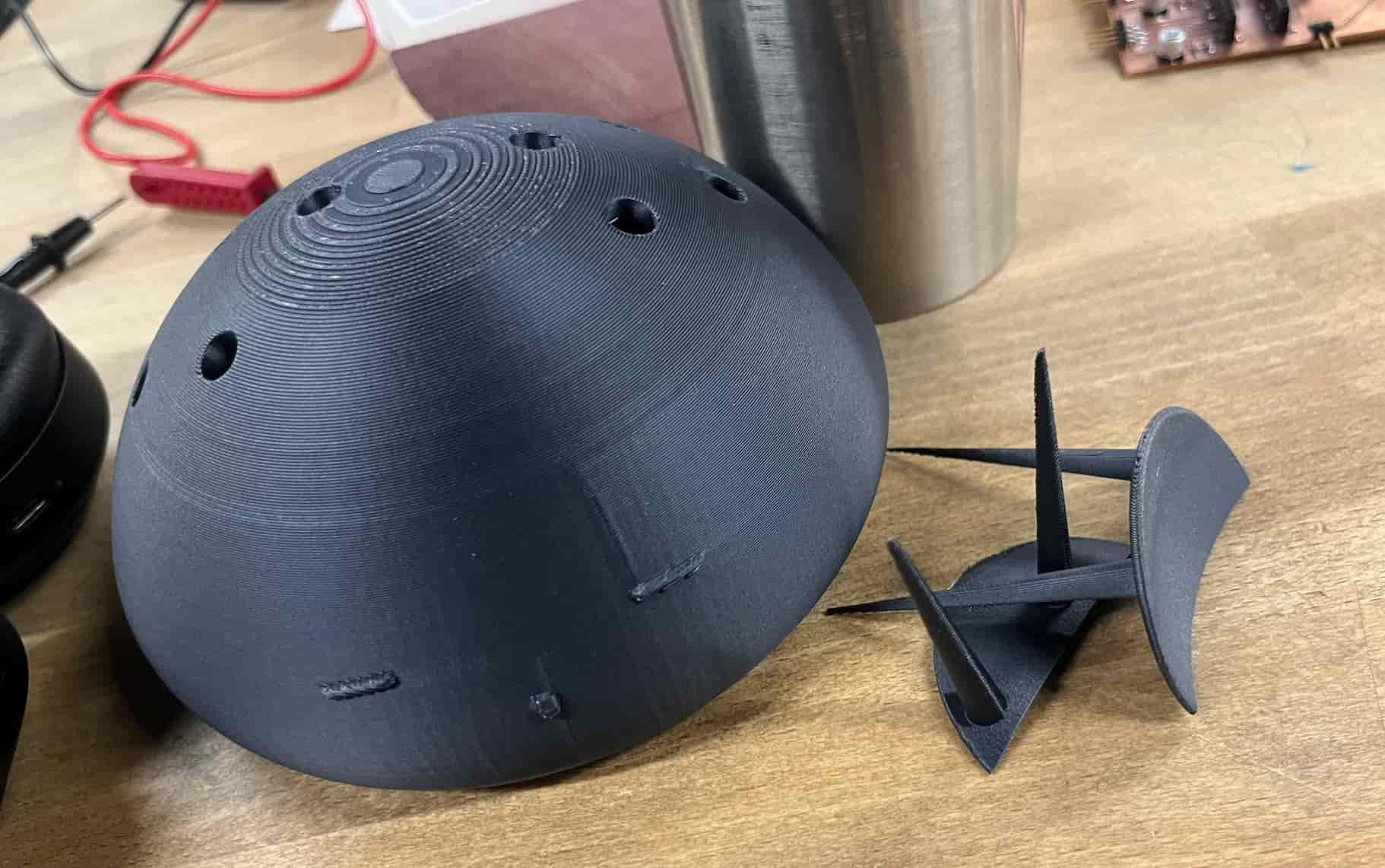
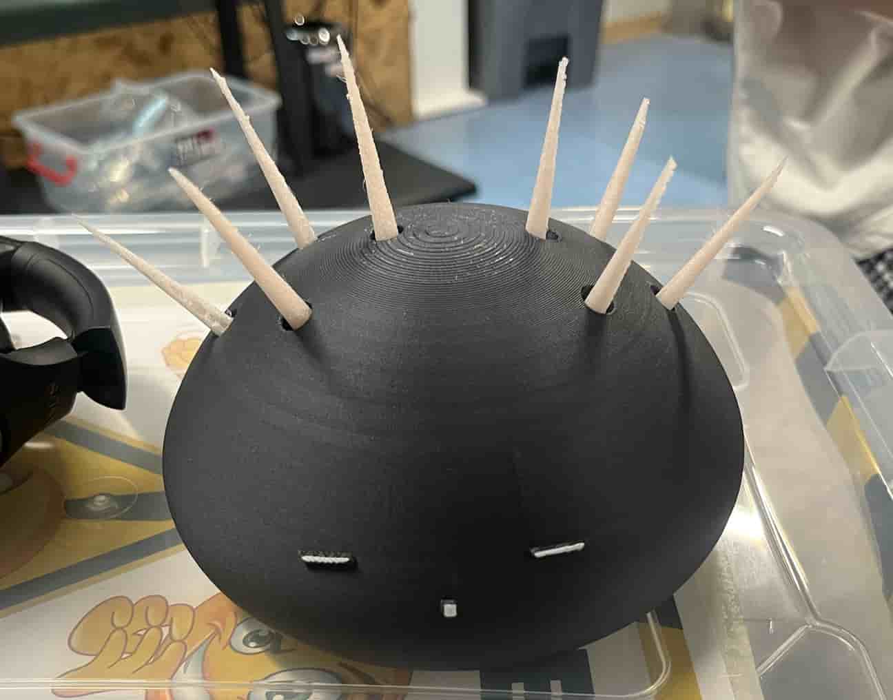
3D Printed Form (design in week 2):
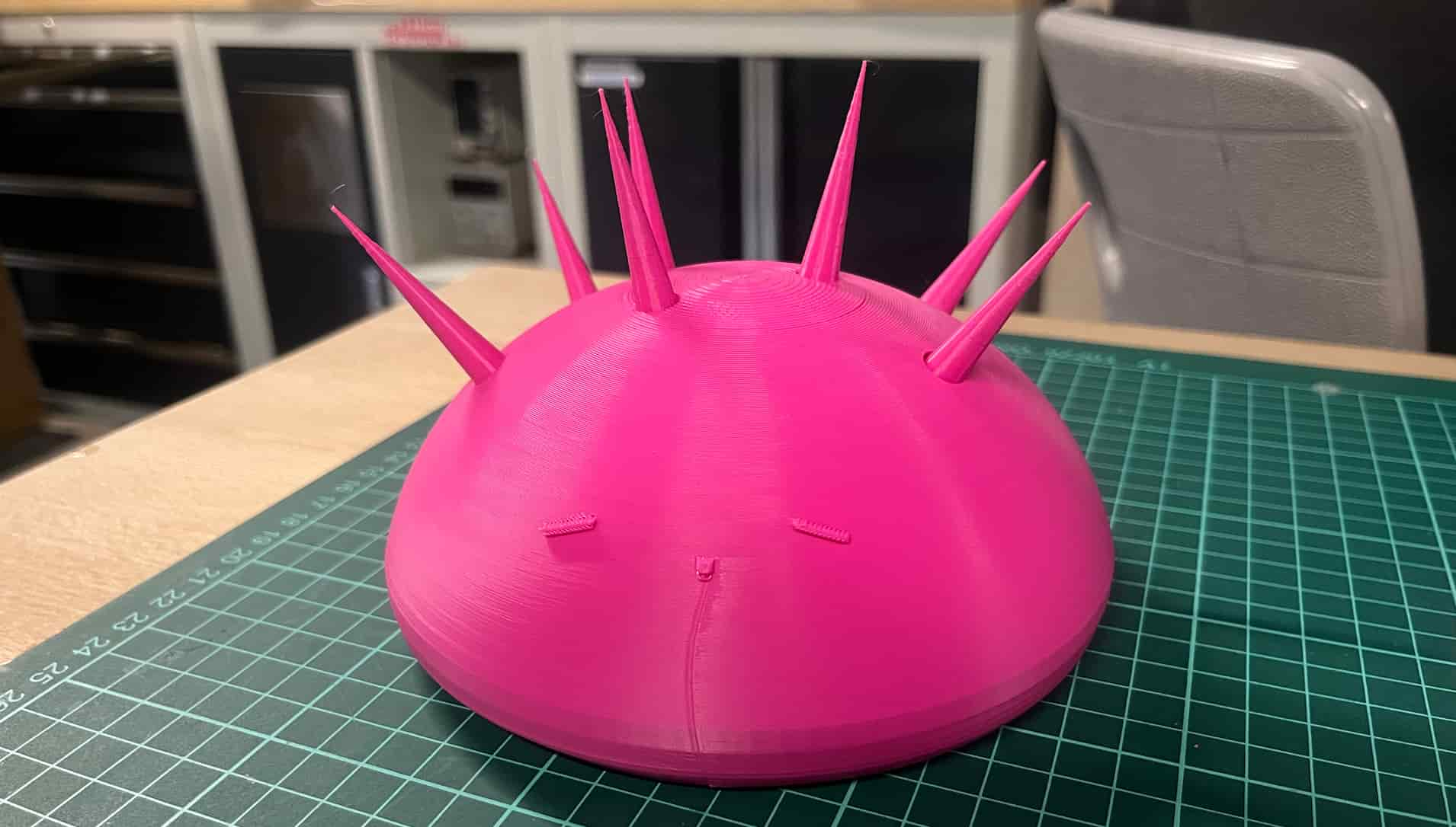
Here is the printed form in a more functional form and the stand it stand on:
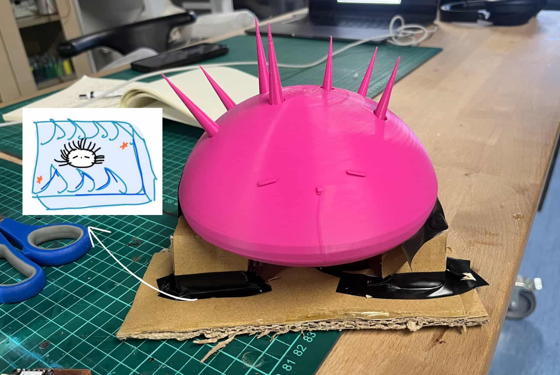
Stand:
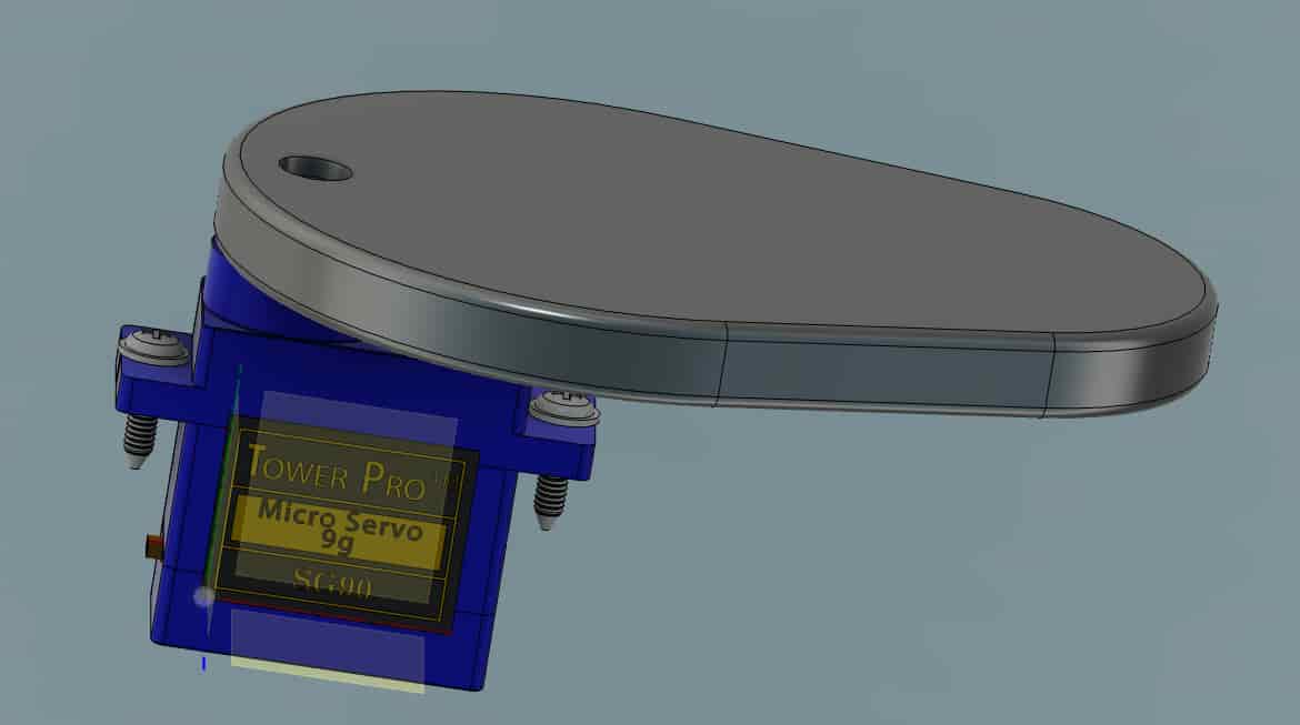
Movement:
Fusion Animation
Final Design
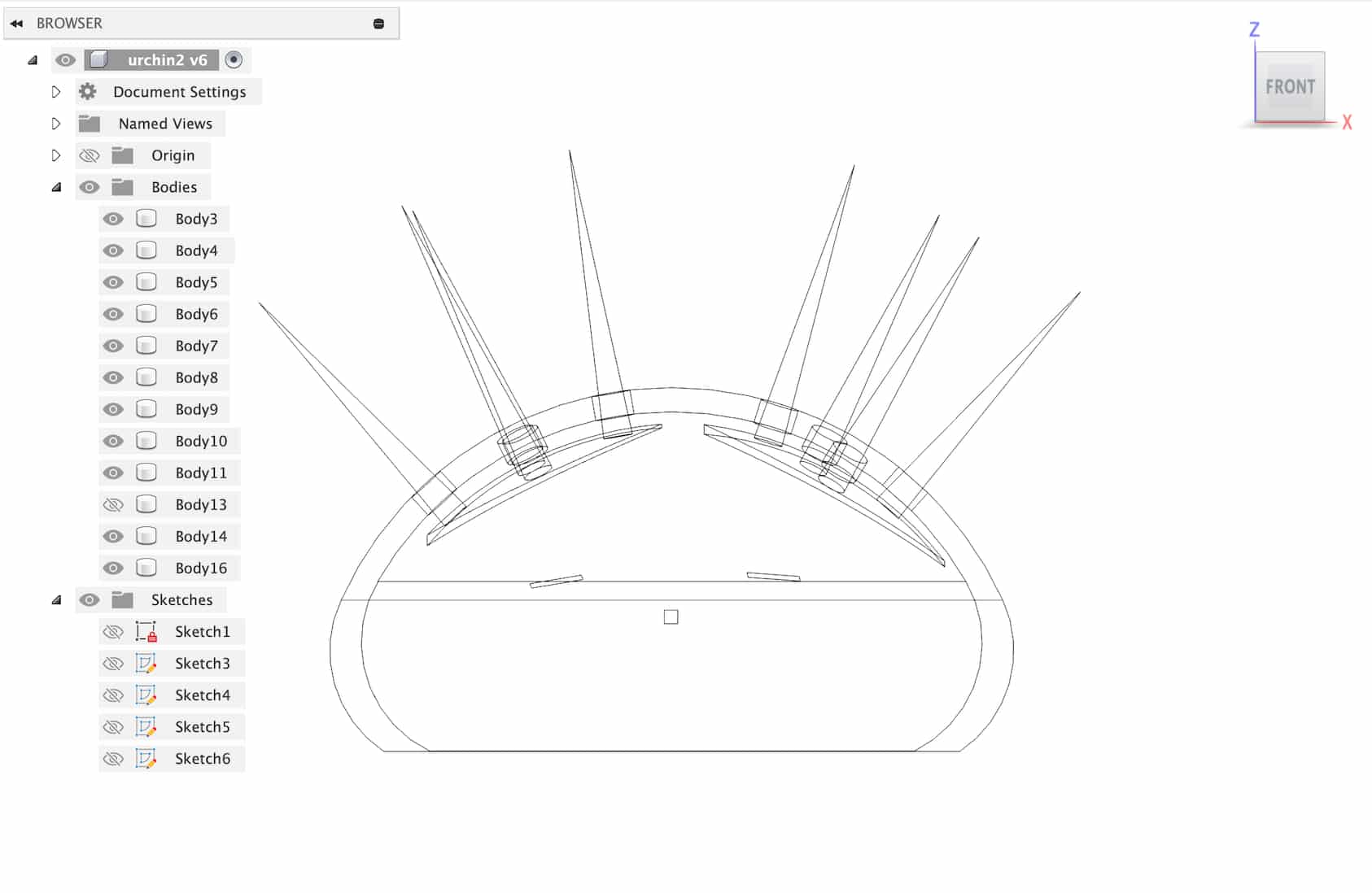
I made an improved version of my design in week 2 for my final design.
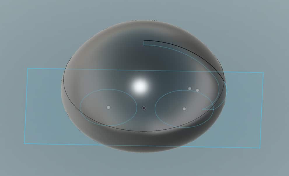
I started out by making a sketch of the outline. I trimmed the corner and added fillet.
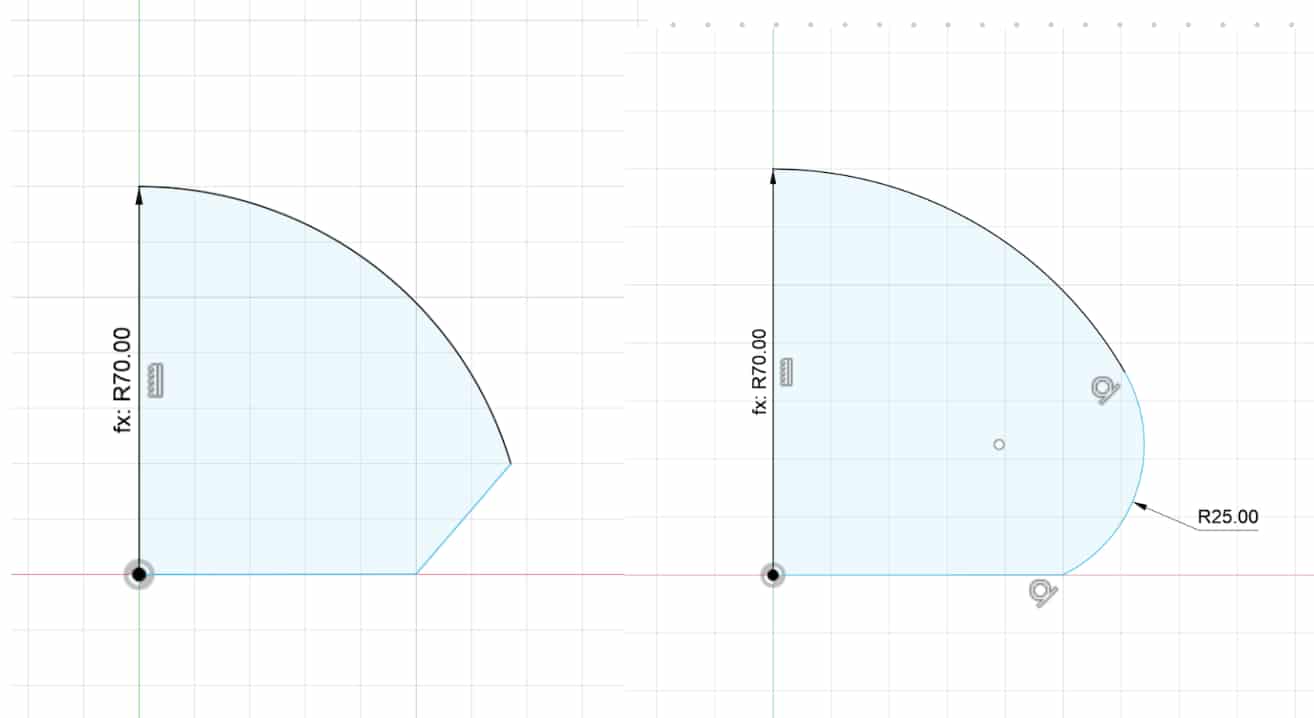
Added an outer layer and trimmed the inner part.
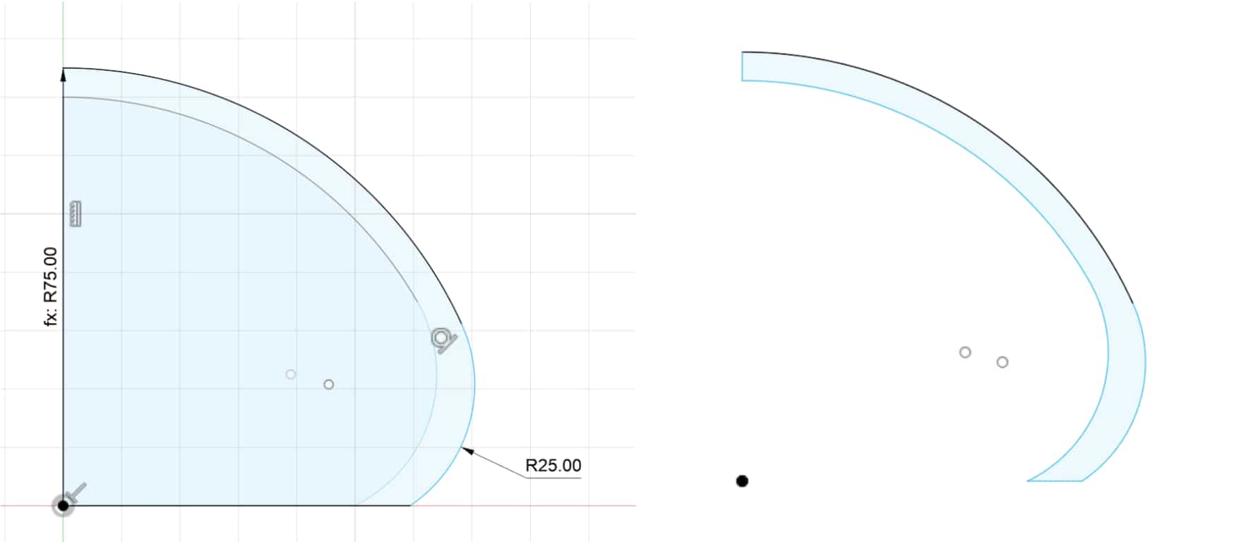
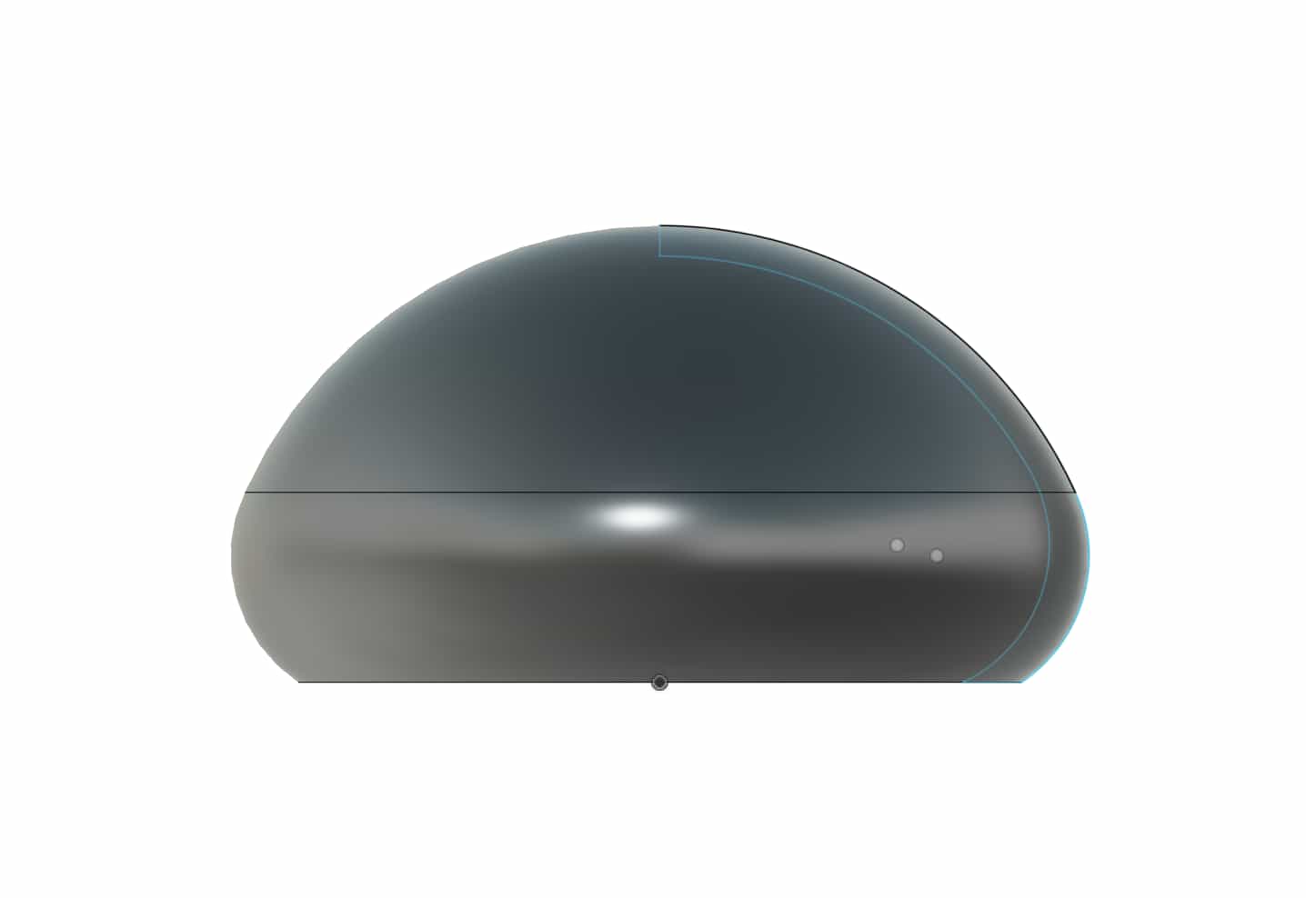
Used Revolve to make it 3D
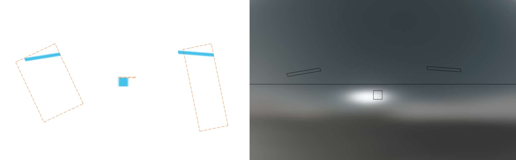
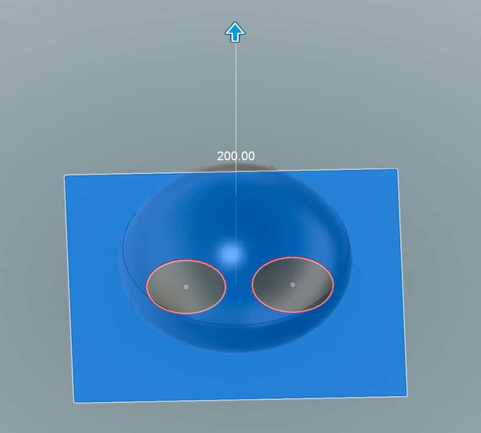
Made a sketch using Text and then used Extrude > Start:Object for the face
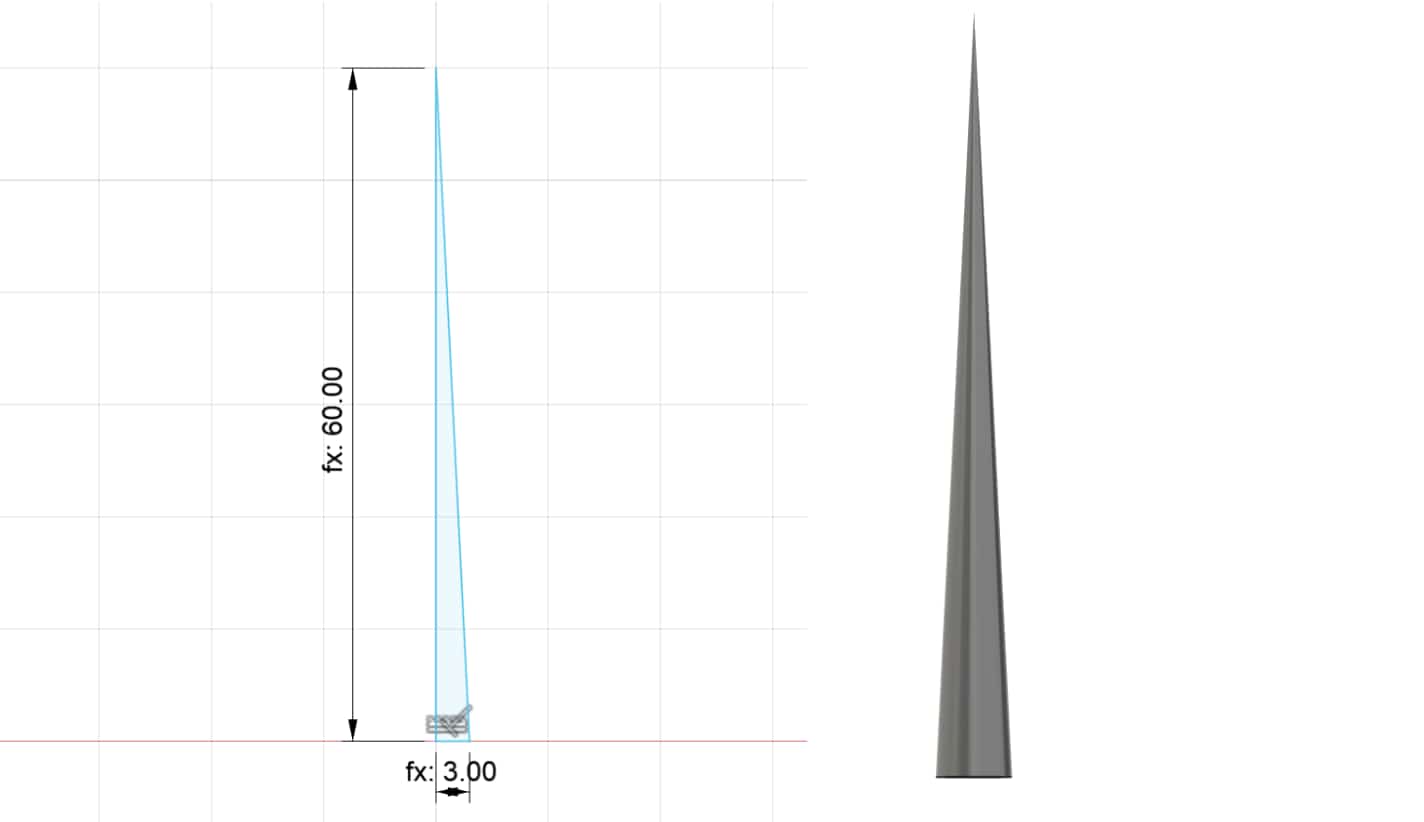
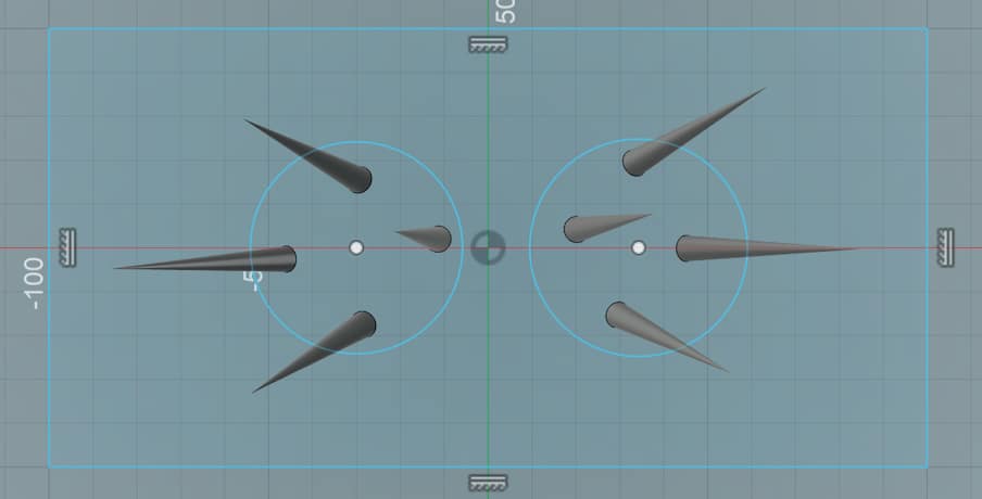
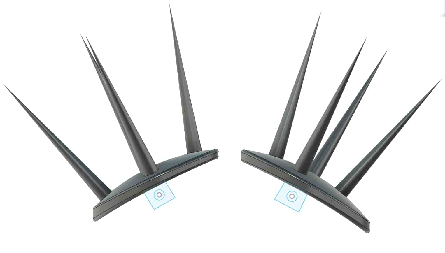
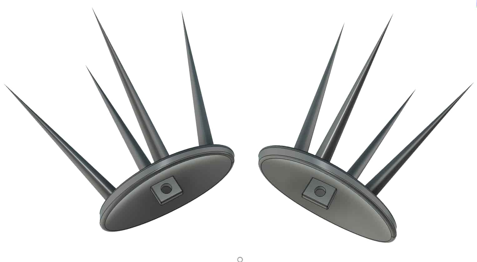
Made a sketch of a right triangle and used Revolve for the spikes
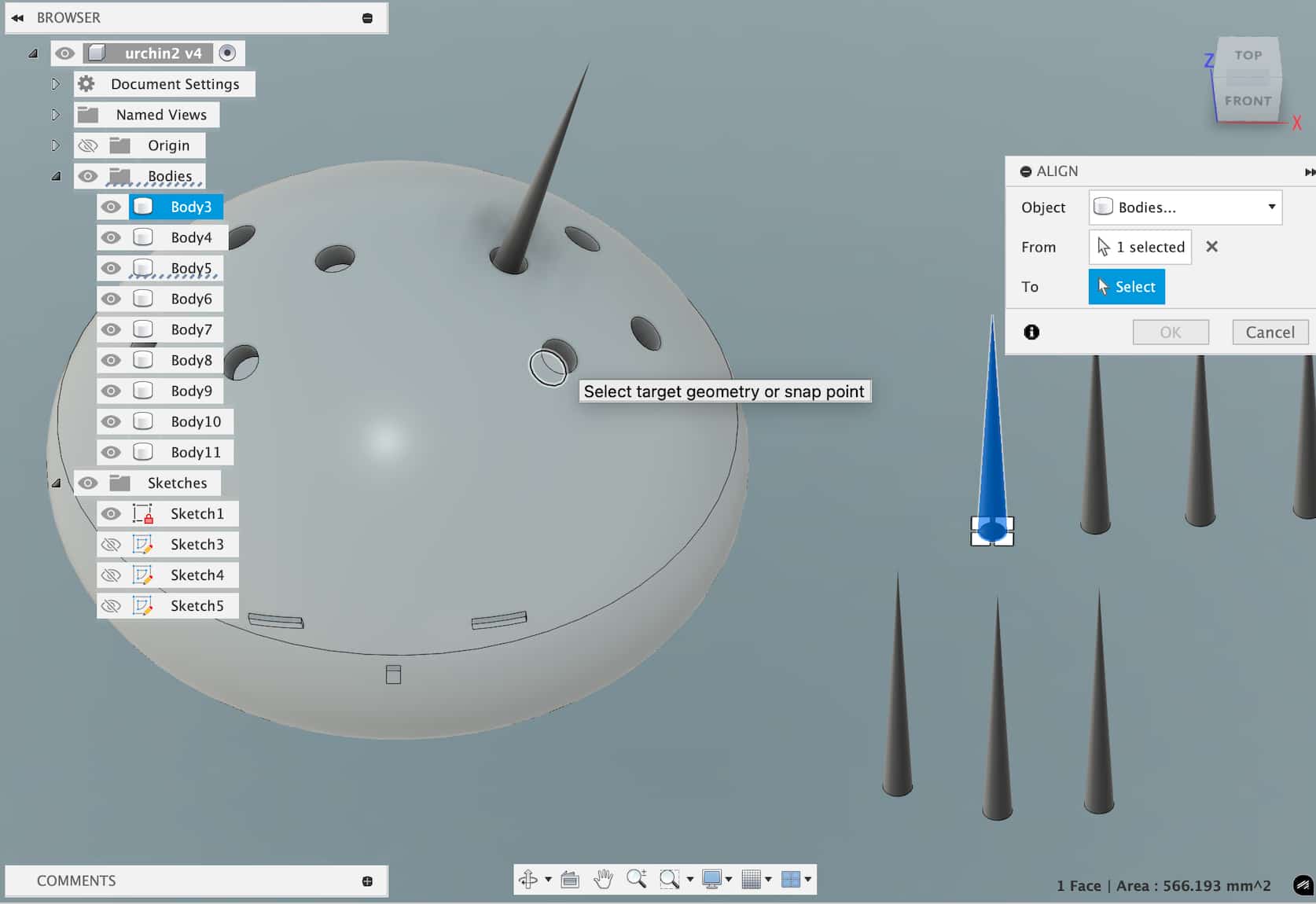
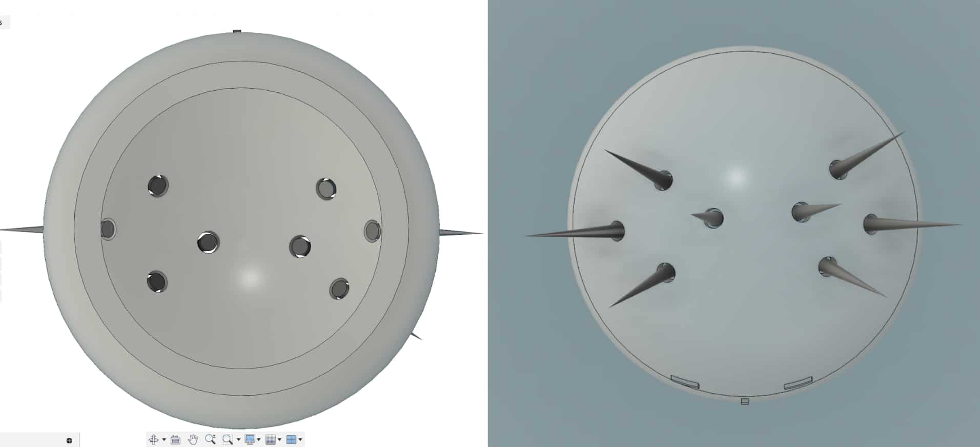
Used Holes to create the holes and Modify > Align to move the spikes into the holes
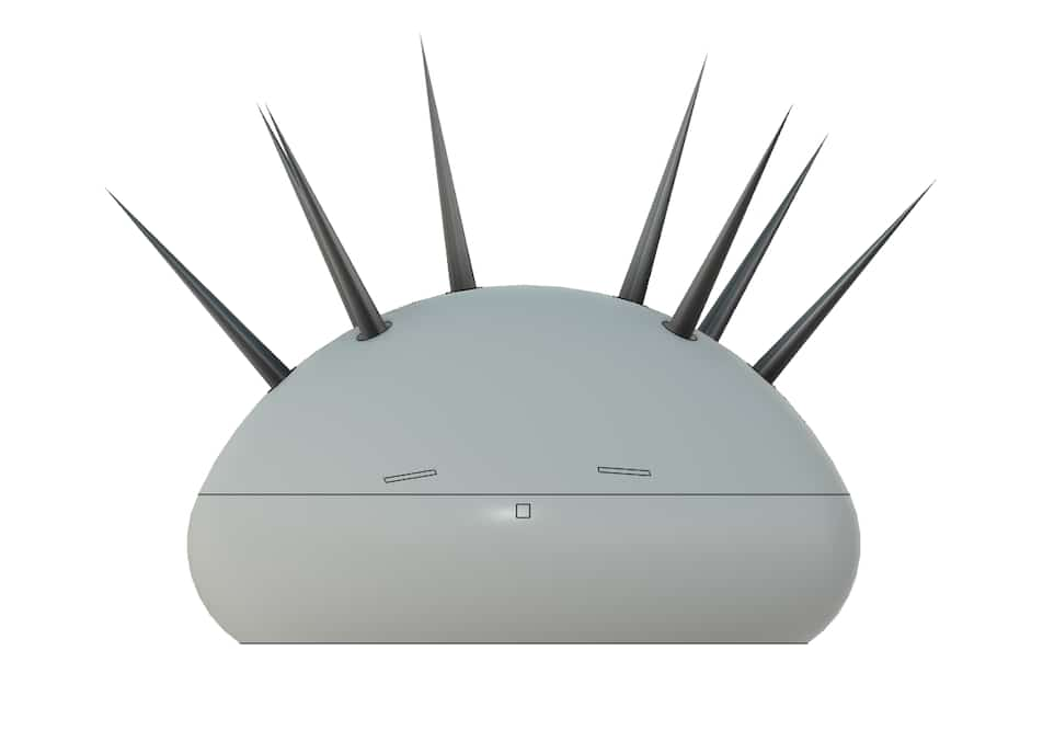
Results:
To create the stands for the spikes I created this sketch
I made the body again from the earlier sketch
Used Extrude to cut the body in the shape of the stands
Stands:
Body with stands:
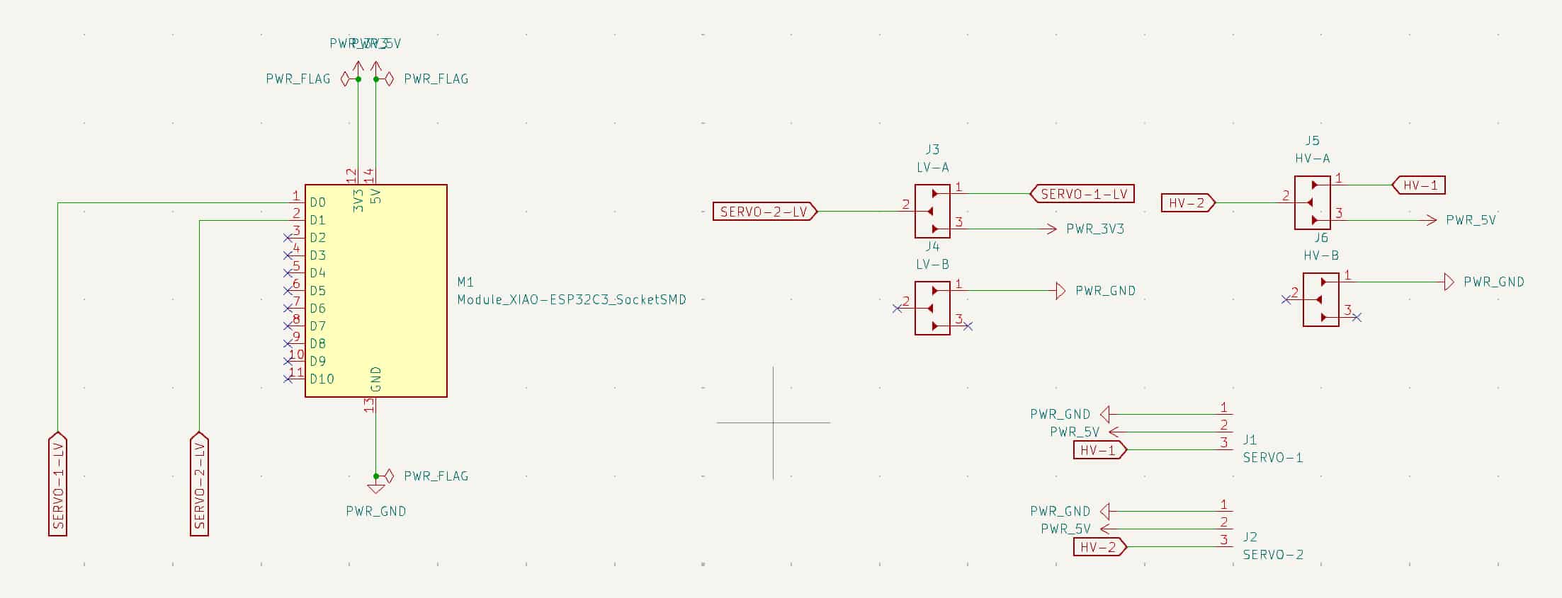
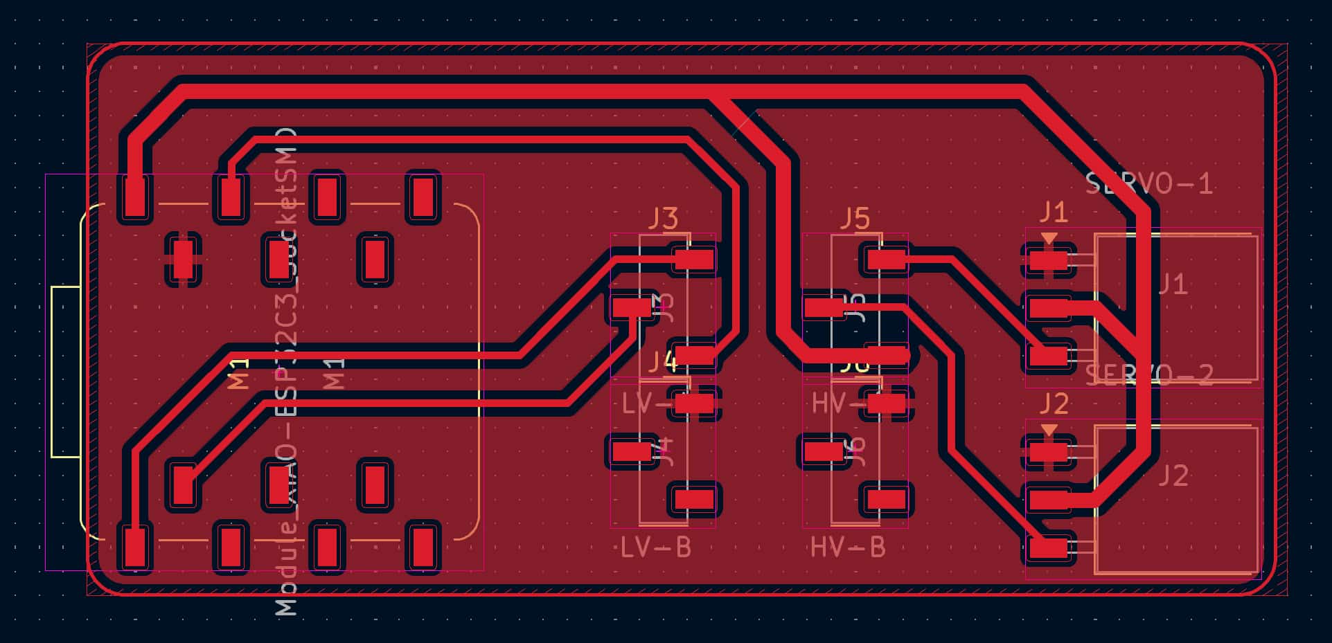
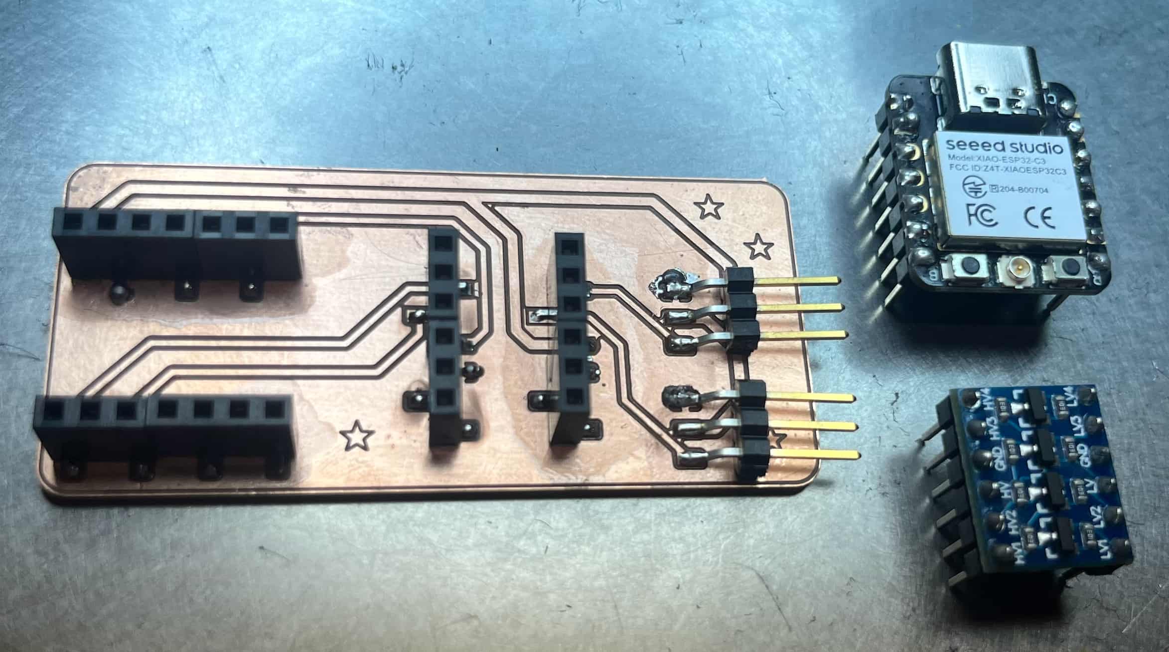
PCB
Putting the Parts Together
When I tried to push the spikes into the holes the stand ended up breaking
So I used a more flexible filament for the spikes. The first filament is the one I used for the body, and the second is the one for the spikes.
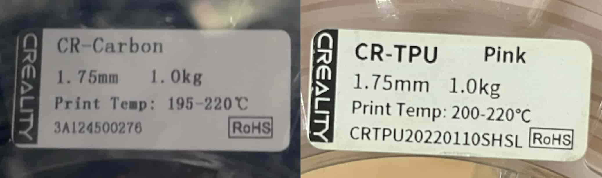
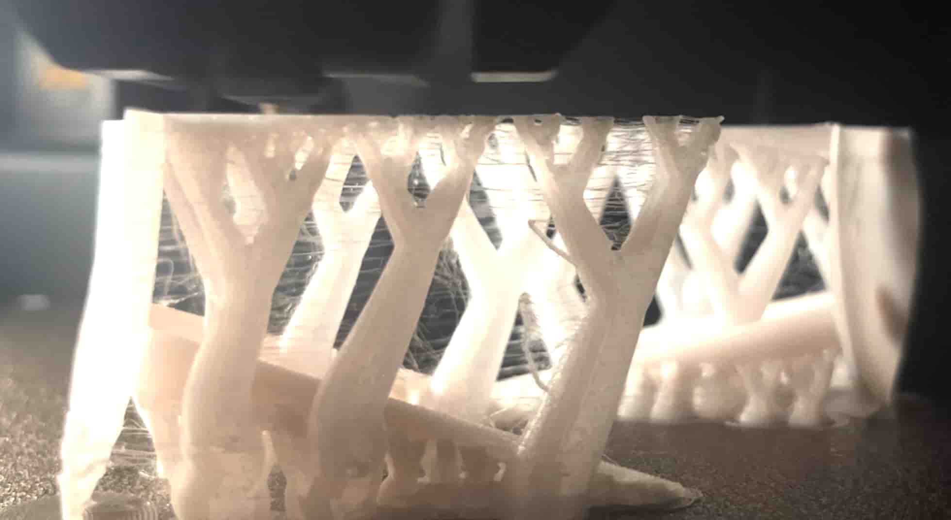
Spikes from CR-TPU:
Trying Different Mechanisms
CAM
My initial idea (as seen in my earlier cardboard prototype) was to use CAM to push the spikes up.
This would work for pushing the spikes up, but then the spikes would remain there since they are placed at an angled position.
I also needed them to come back down. So I tried to achieve that with a rubber band
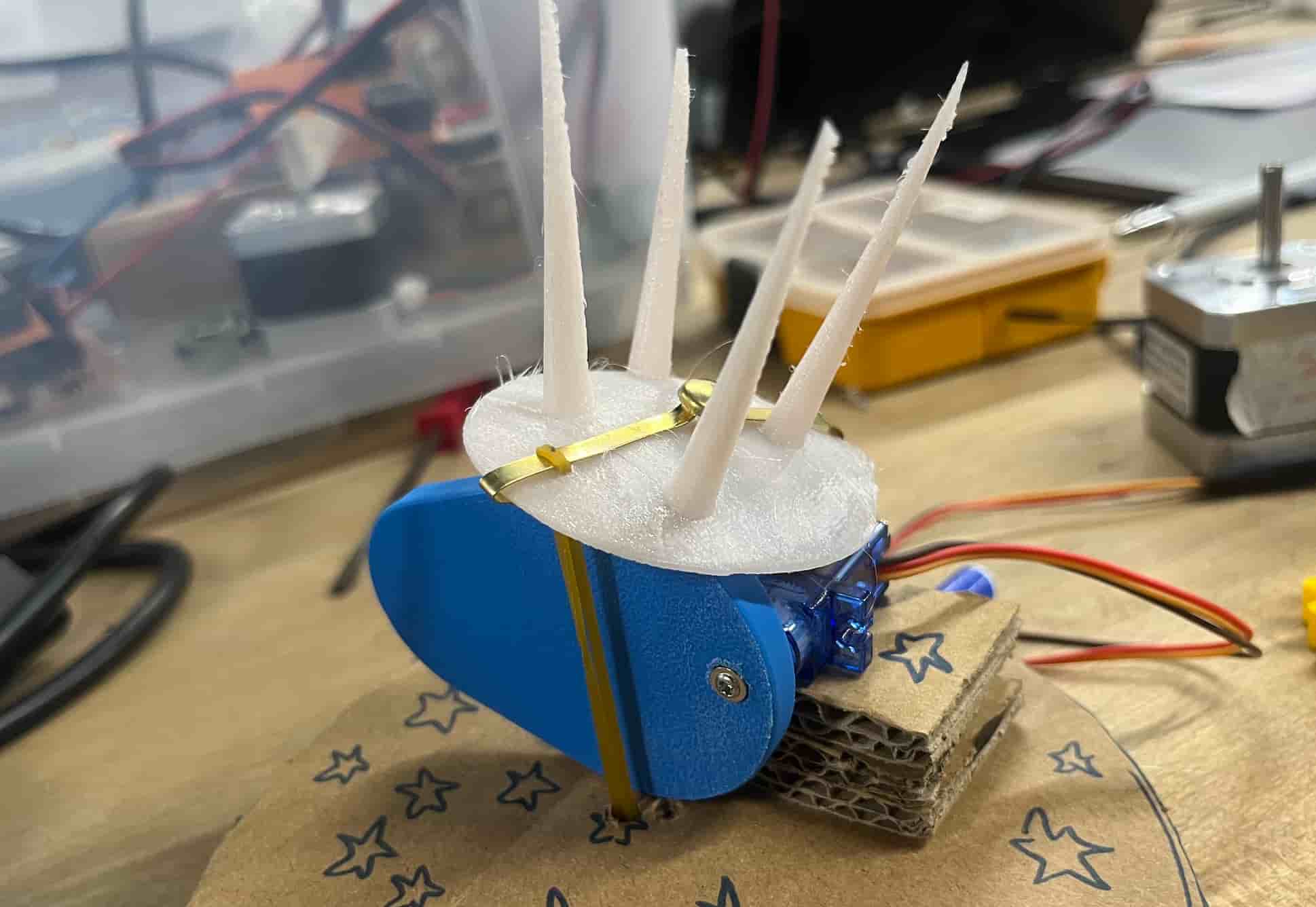
But it wasnt very succesful
Slider Crank
I then looked into the slider crank mechanism and it seemed to be what I needed
CAD - Continue
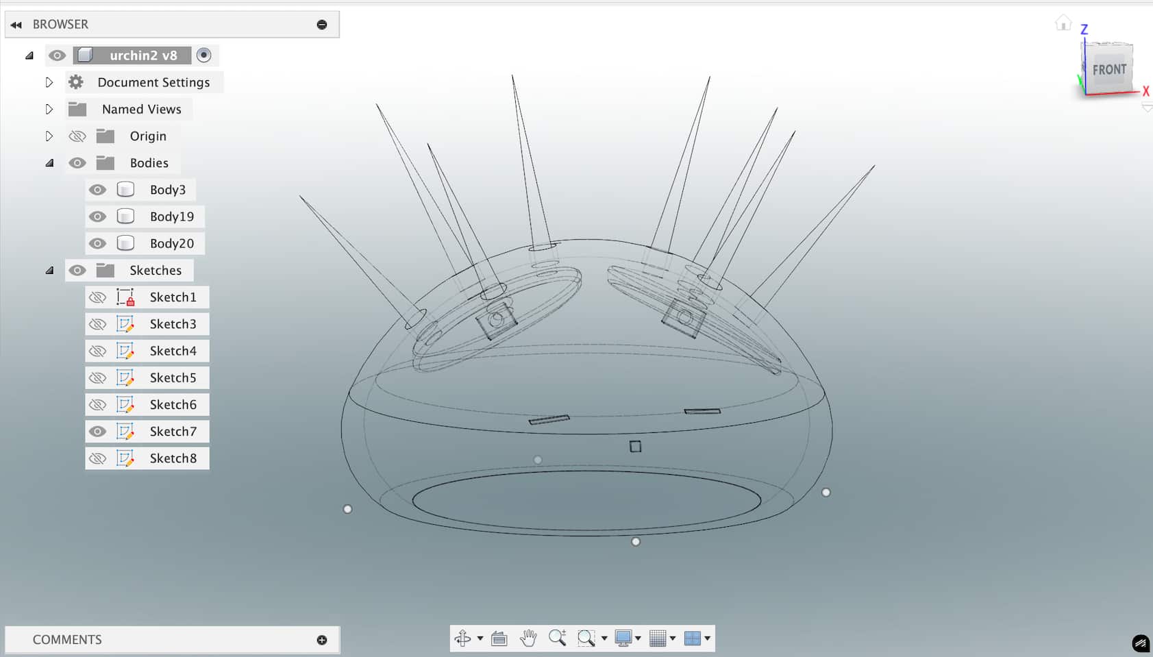
I added a place to put in screws under the spikes after switching to slider crank.
I made the following sketch (4mm holes for screws)
And then used Extrude and Move to position it right under
CAD - Stand
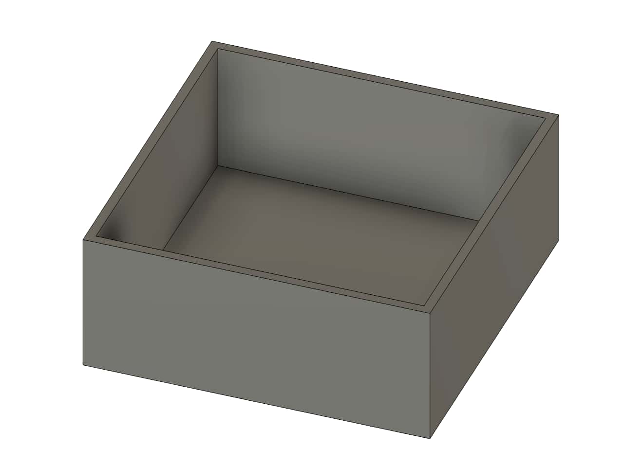
I needed some extra space at the bottom for the mechanism so I started working on a stand.
I started out by drawing a square sketch. I Extruded the sketch and used Shell to create the box shape.
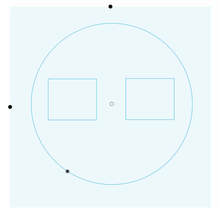
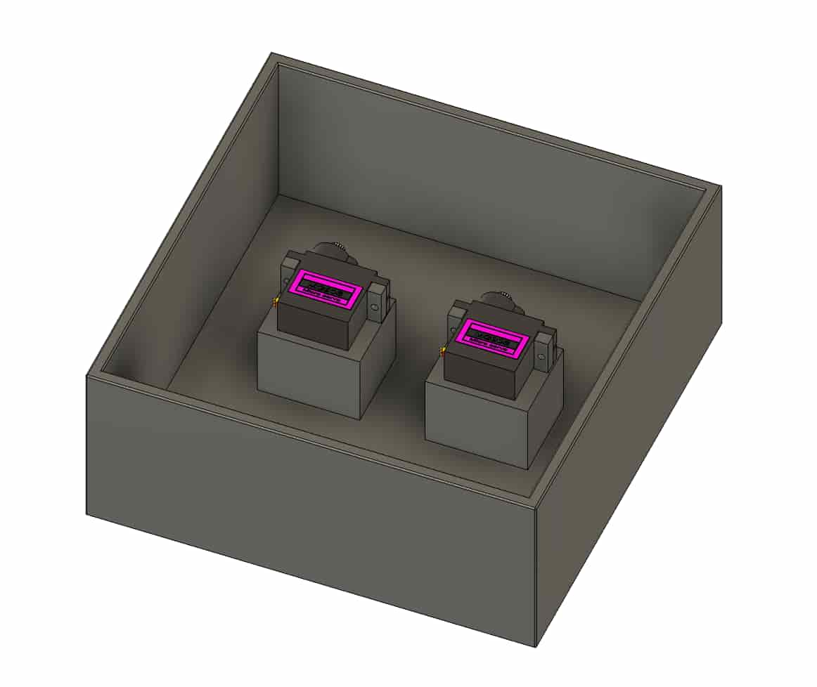
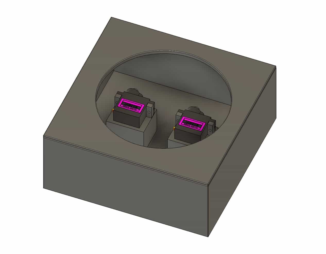
Created another sketch to create the stand for servos.
Got step files for servo from grabcad.
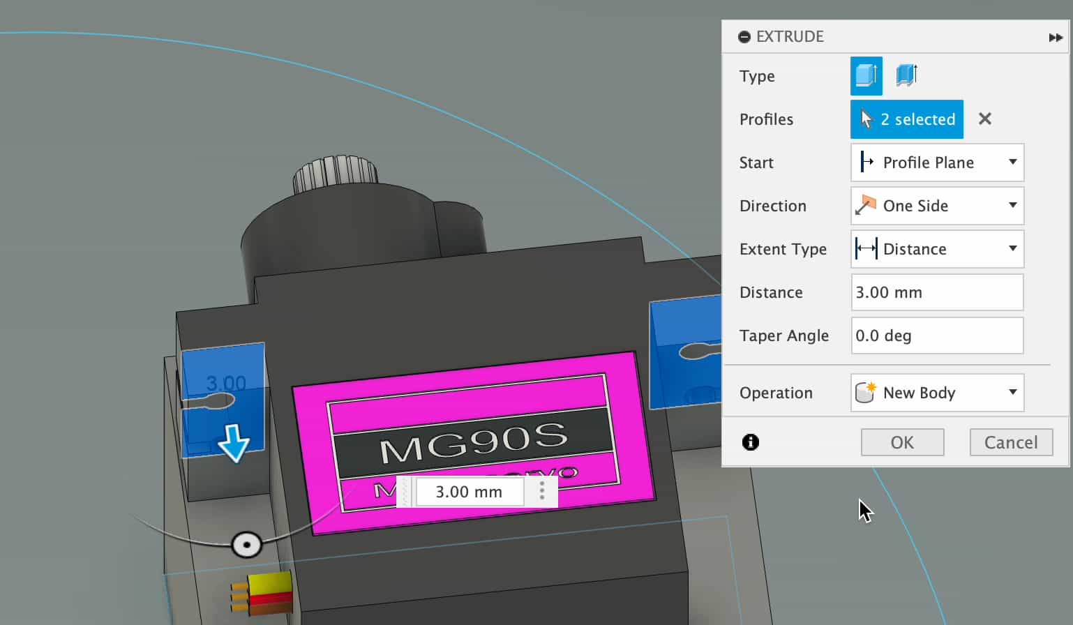
Extruded the squares and then Extruded the screw parts of the servos.
To create the lid, I pressed P on the keyboard for Project and pressed the top layer of the box.
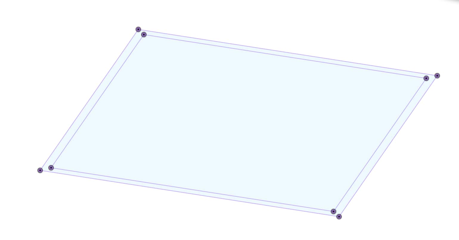
I extruded the inner square by -2 and the outer by 2.
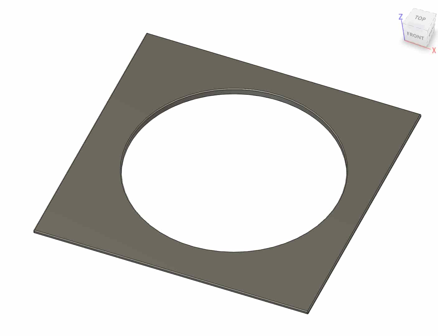
After the lid was done I created a circle sketch on top of the lid to create the empty middle.
Servo - Update
The servos worked fine on their own but I started faced power problems when I added the wood CAM and spikes. The movement was jittery and they were barerly moving. I solved this problem by moving onto stronger servos - MG996R. I changed the CAD design accordingly.

System Integration And Packaging
Details of packaging and what the inside of the stand look like in real life can be found here.
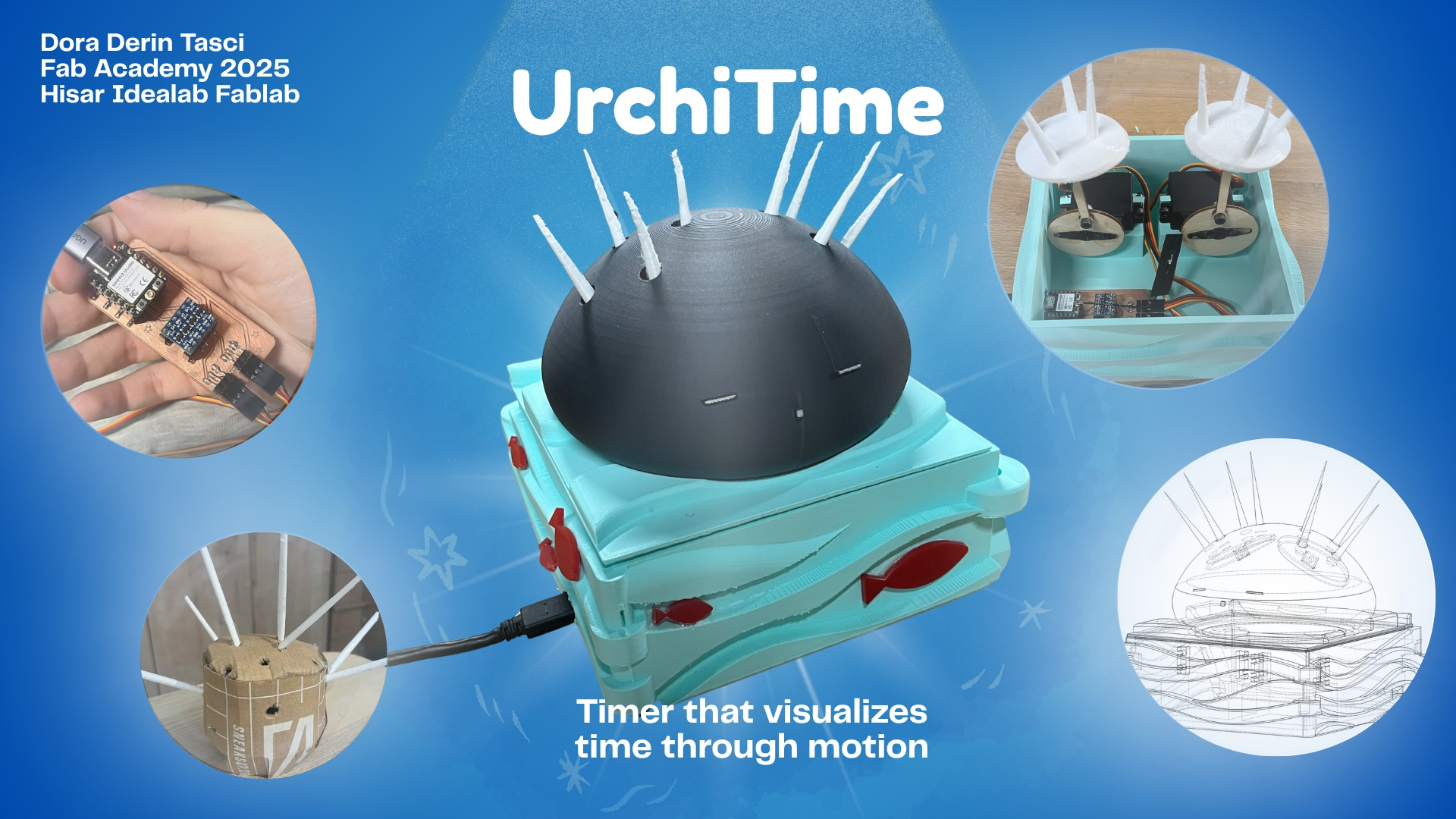
Presentation
Poster
Video
Bill of Materials
| Material | Quantity | Cost per Unit (USD) |
|---|---|---|
| ESP32-C3 Microcontroller | 1 | $5 |
| Servo MG996R | 2 | $3.59 |
| Logic Level Converter (3.3 V-5 V) | 1 | $0.39 |
| Logic Level Converter (3.3 V-5 V) | 1 | $0.39 |
| 5V Power | 1 | s$2.28 |
Files
PCB, CAD design and code files are in this zip folder