Week 8: Electronics Production
Click to access the group assignment
This week, I learned how to produce a custom PCB using a CNC milling machine. The process included file preparation, toolpath generation, probing, milling, and component soldering.
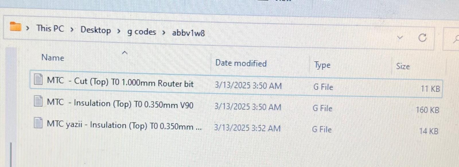
I started by importing my Gerber files into Cube 3D CAM Pro. This software allowed me to visualize the PCB design and generate G-code for the engraving and cutting operations.
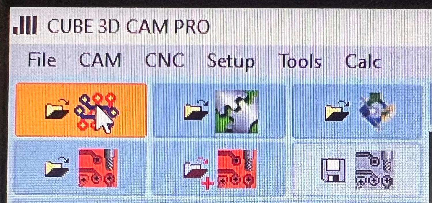
After importing the Gerber files, I previewed the traces and outline. This helped me confirm the alignment, scaling, and overall board layout.
Generating Toolpaths in Cube 3D CAM Pro
- Engraving: V90 engraving bit (~0.1mm depth) for isolating traces
- Cutting: 1.0mm flat end mill (~1.8mm depth, multiple passes)
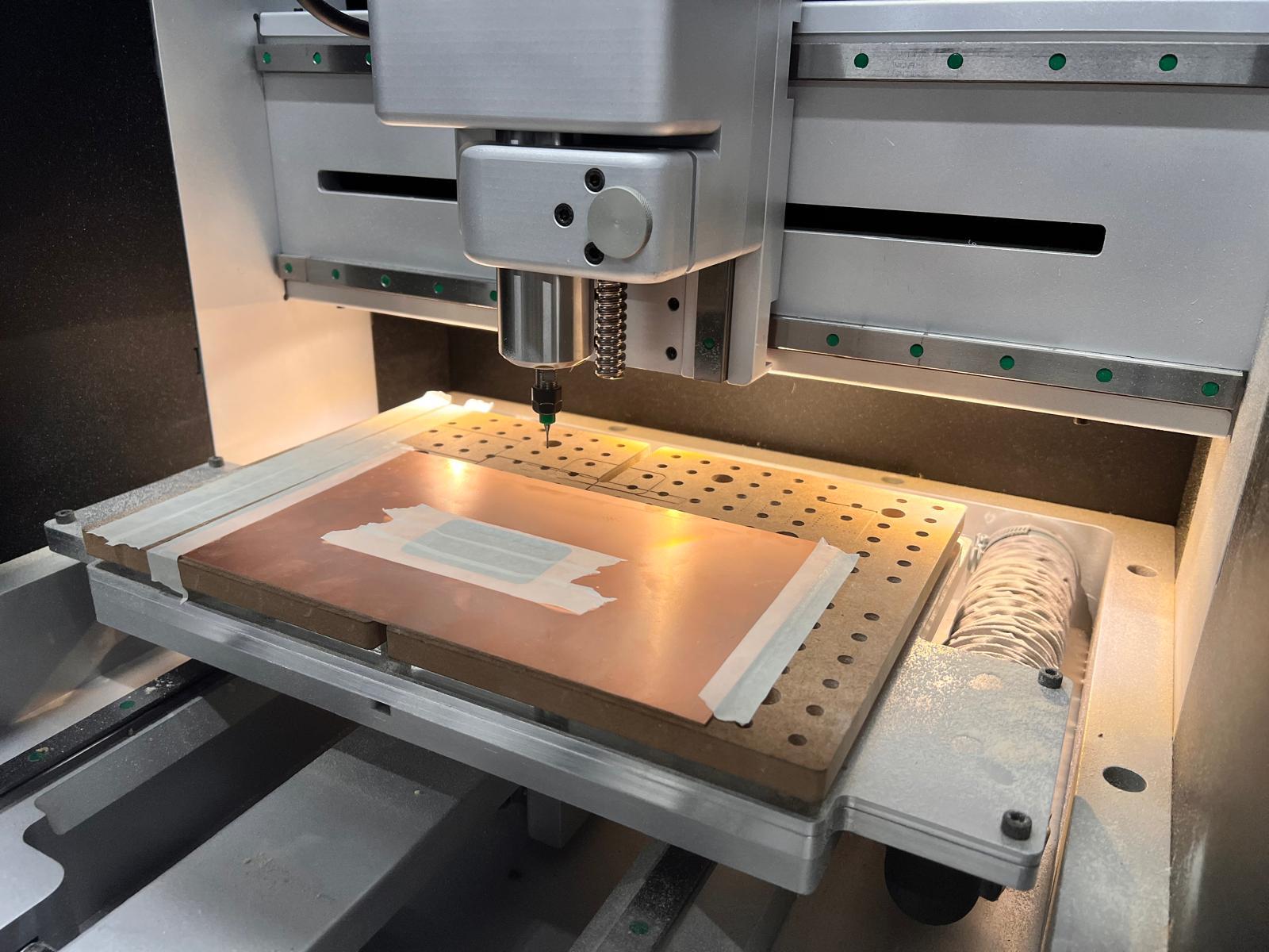
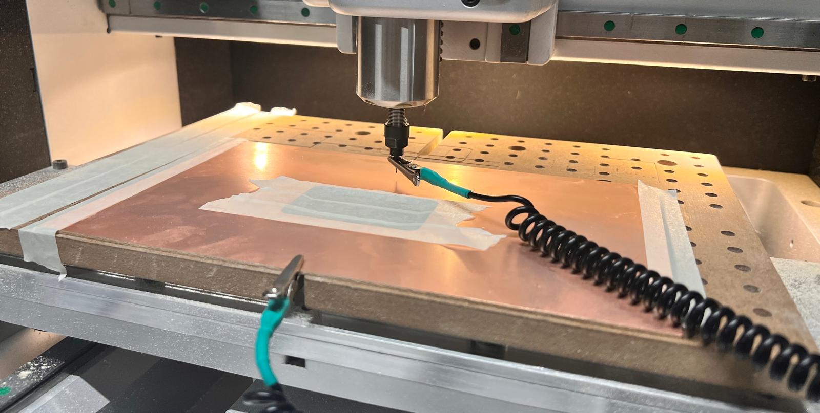
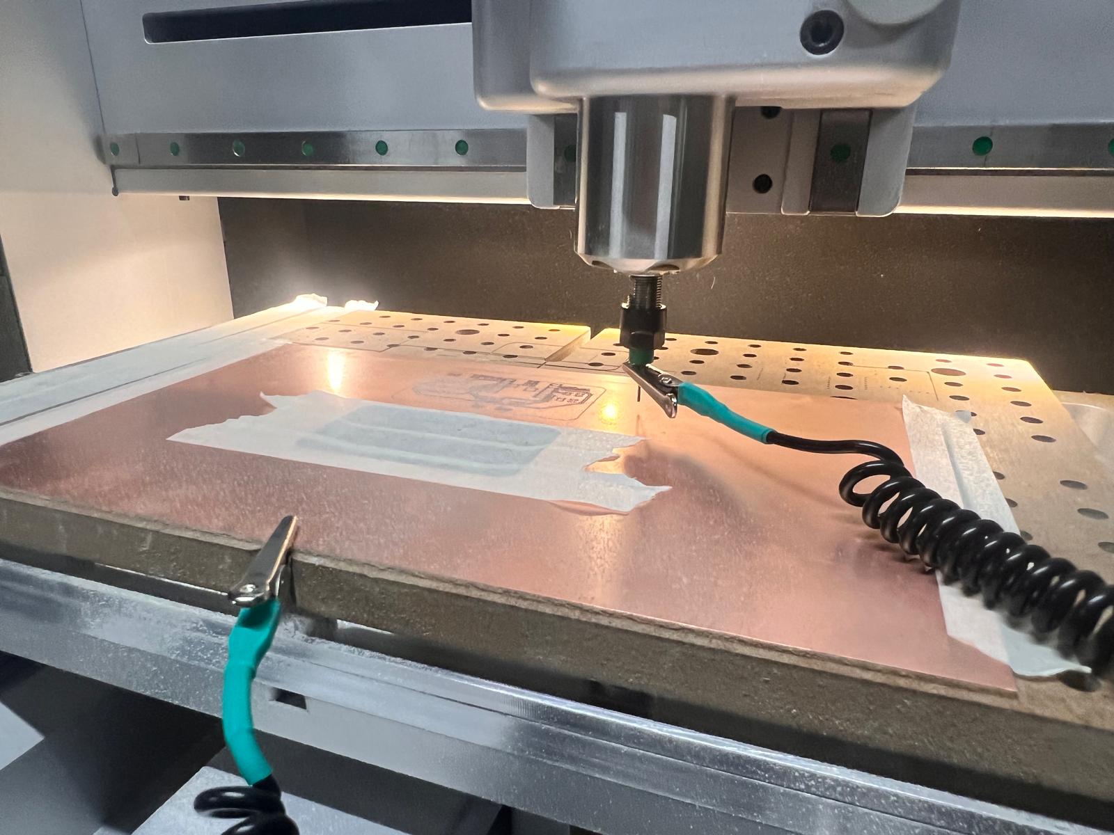
The copper-clad board was fixed with tape on a sacrificial layer.
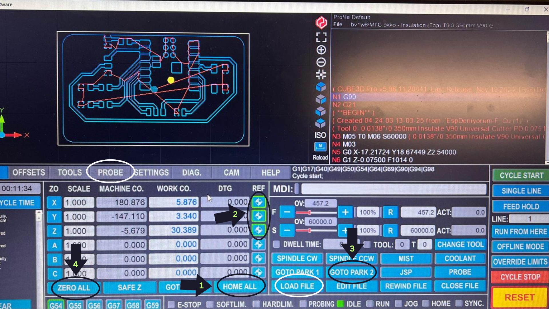
Machine Setup Sequence:
- Click HOME ALL
- Wait for all indicators to turn green
- Click GOTO PARK 2
- Click ZERO ALL
- Change the bit and begin probing
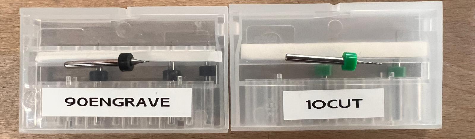
Bits used:
- V90 Engraving Bit
- 1.0mm End Mill
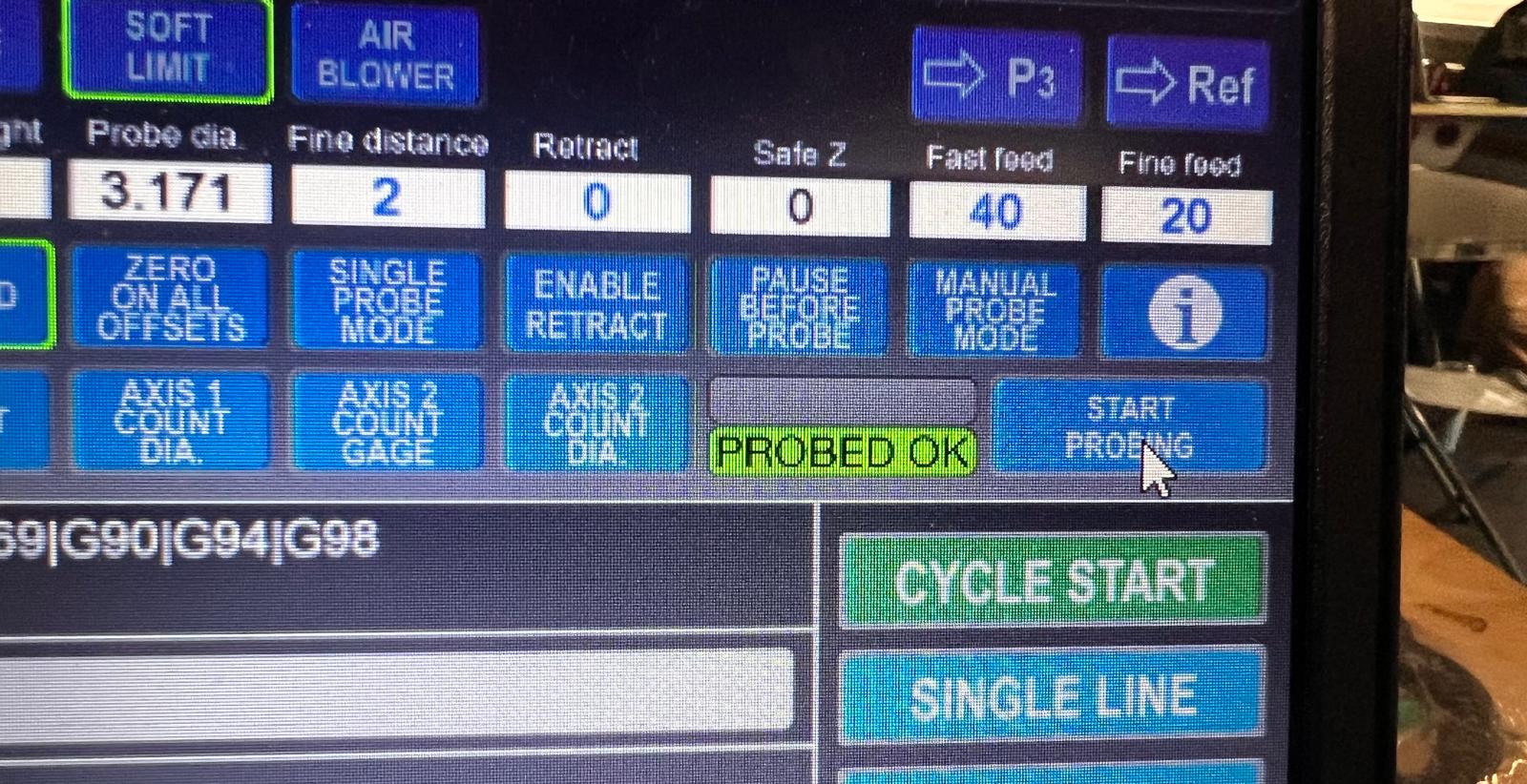
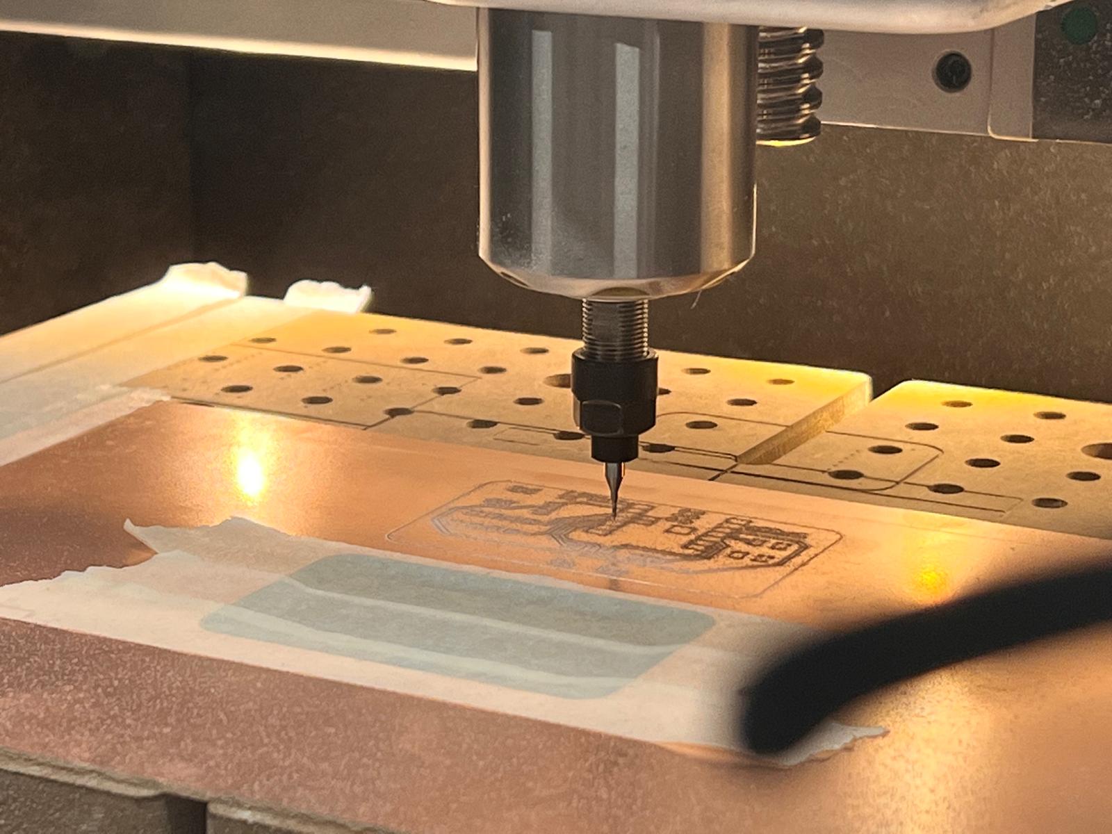
I used surface probing to determine the Z-offset of the copper board.
Started engraving traces with V90 bit.
Re-probed after switching to the 1.0mm bit.
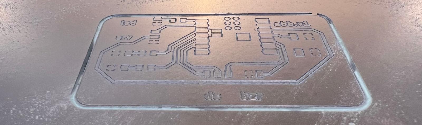
Traces and outline milled successfully.
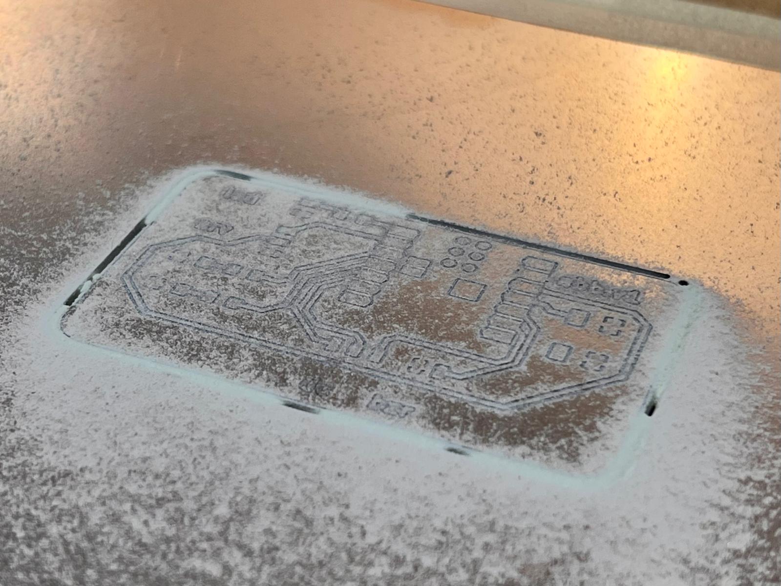
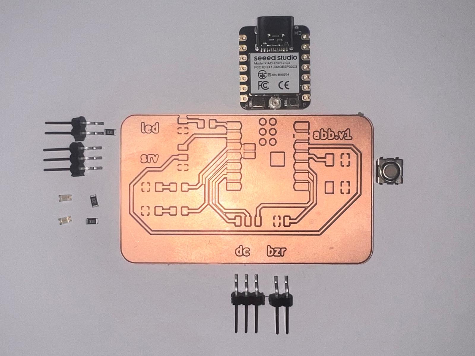
Cleaned PCB ready for component soldering.
First soldering attempt had some issues.
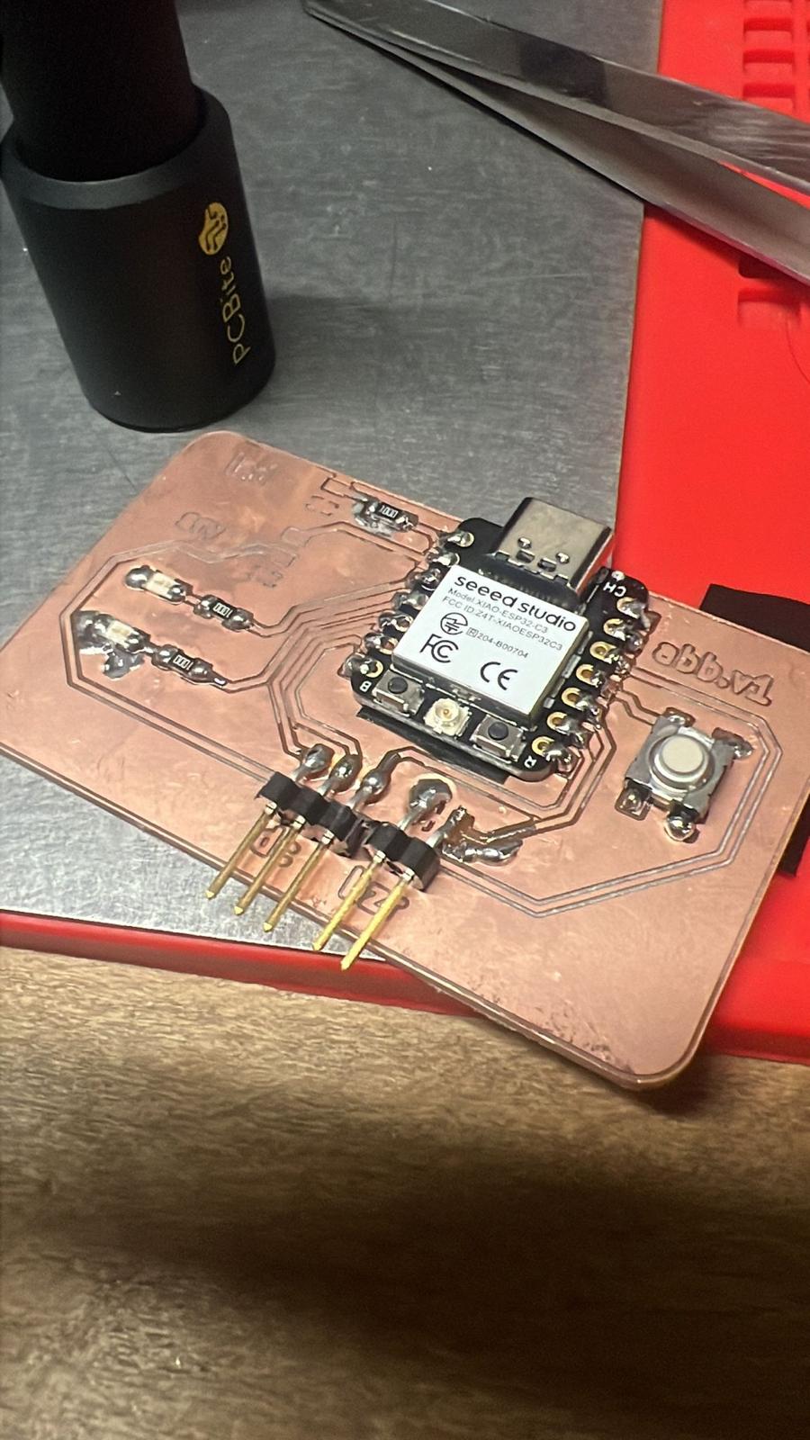
Successfully fixed the solder joints in a second pass.
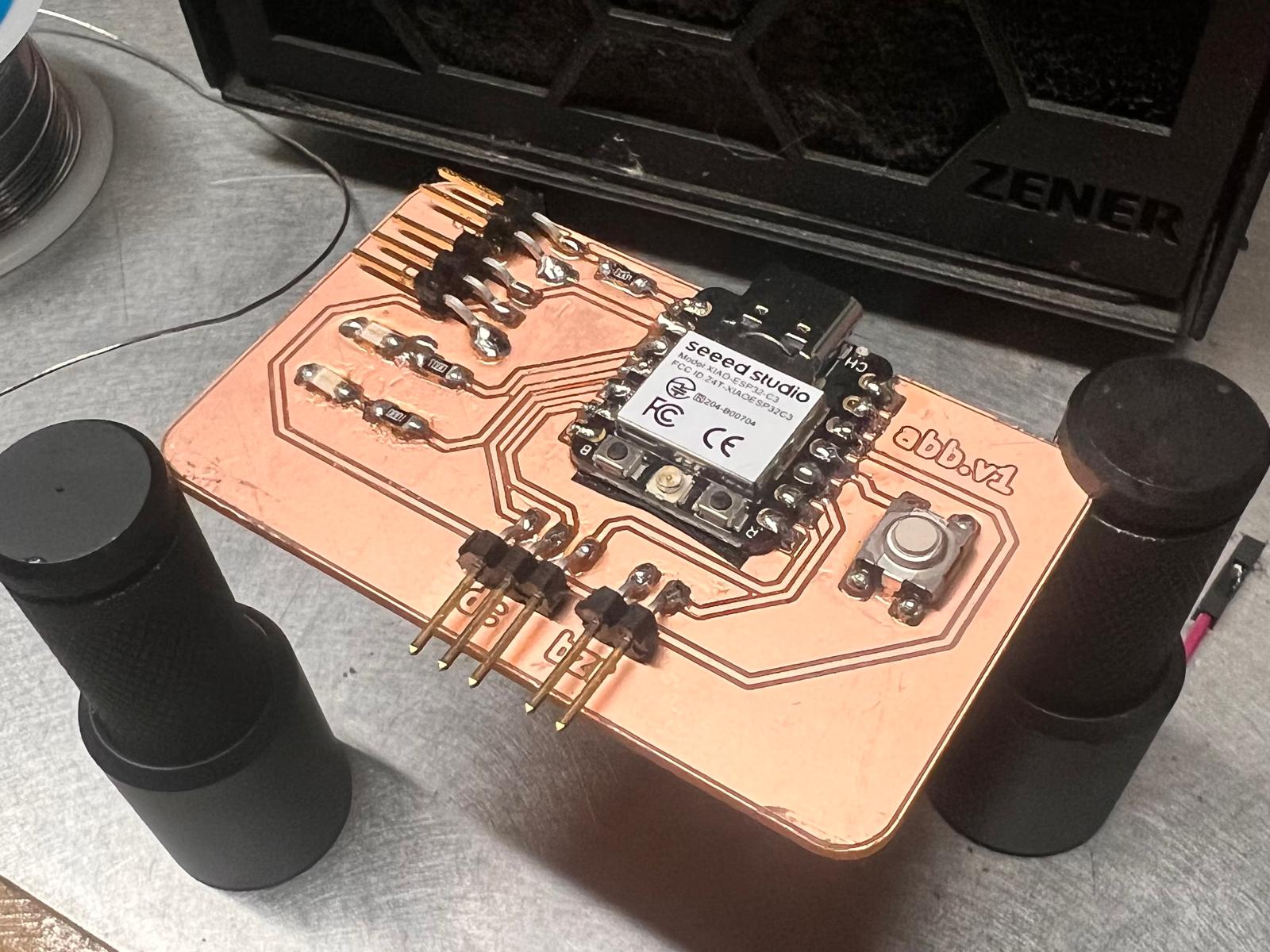
Testing the Board Functionality
Uploaded code with Arduino IDE to test LEDs and buzzer via button input.
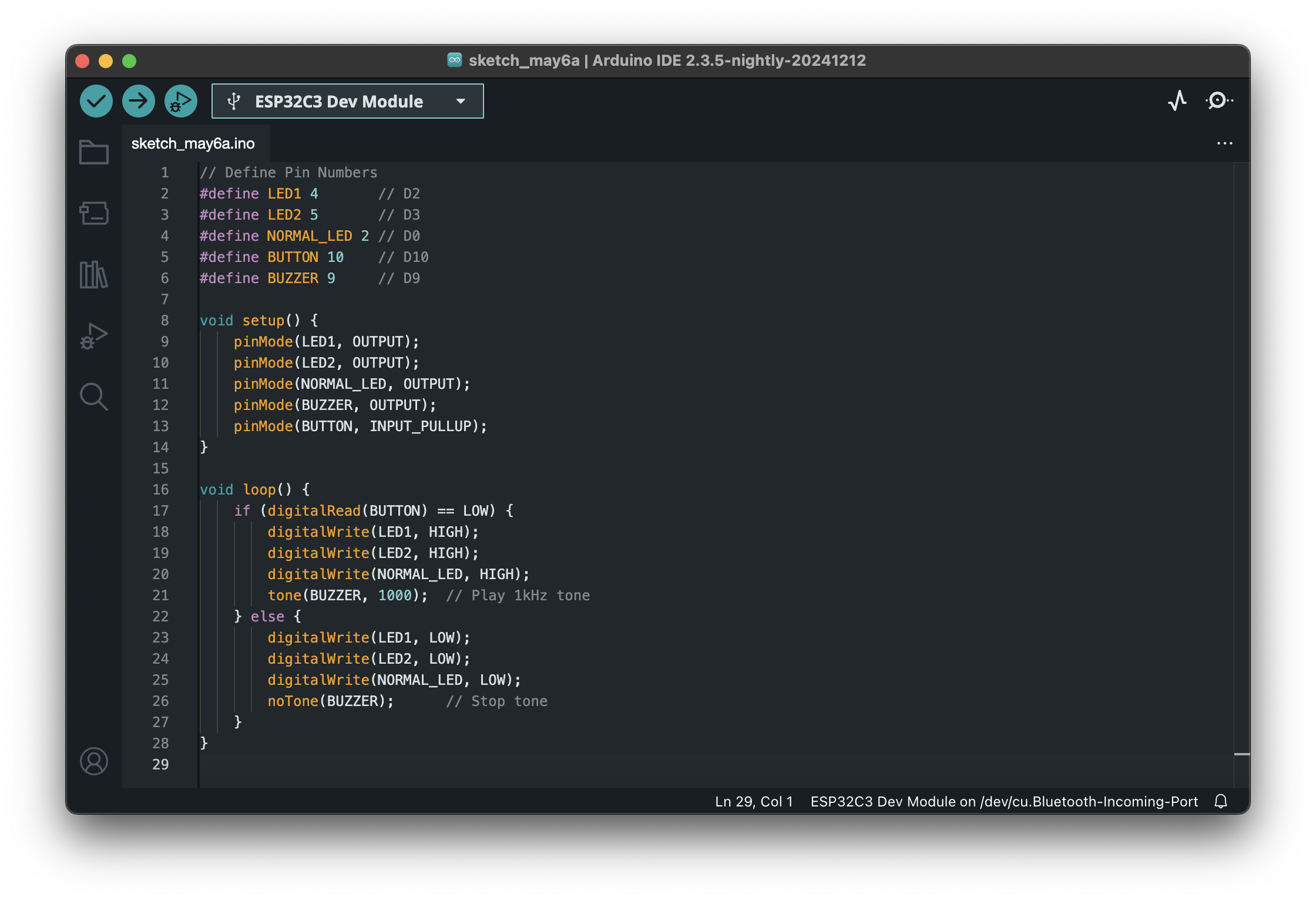
Code
#define LED1 4
  #define LED2 5
  #define BUTTON 10
  #define BUZZER 9

  void setup() {
    pinMode(LED1, OUTPUT);
    pinMode(LED2, OUTPUT);
    pinMode(BUZZER, OUTPUT);
    pinMode(BUTTON, INPUT_PULLUP);
  }

  void loop() {
    if (digitalRead(BUTTON) == LOW) {
      digitalWrite(LED1, HIGH);
      digitalWrite(LED2, HIGH);
      tone(BUZZER, 1000);
    } else {
      digitalWrite(LED1, LOW);
      digitalWrite(LED2, LOW);
      noTone(BUZZER);
    }
  }
Summary
- LEDs light up when button is pressed
- Buzzer makes sound at 1000 Hz
- Button uses internal pull-up and is responsive
Final video
Hero Shot


