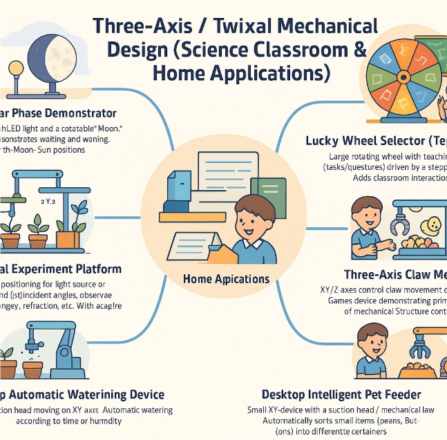
This week, I will design a simple mechanical device — a Lucky Wheel Selector / Topic Spinner — to increase student engagement in the classroom.
Learning Objectives
Group Assignment
Design a machine that includes mechanism + actuation + automation + application
Build the mechanical parts and operate it manually
Actuate and automate your machine
Document the group project
Individual Assignment
Document your individual contribution
Learning highlights
Lucky Wheel Selector / Topic Spinner
I used AI assistance to help me with the creative part.
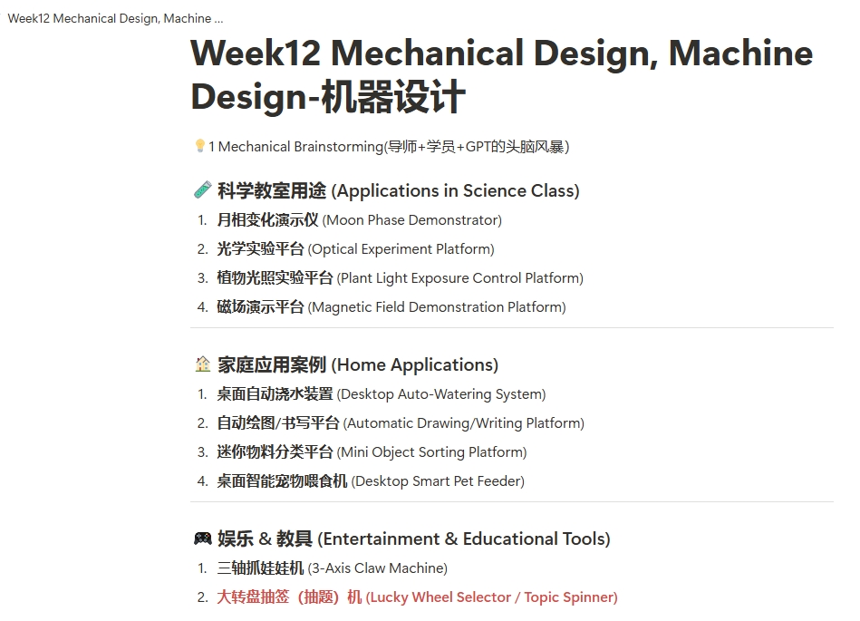
1 Mechanical Brainstorming
I had a two-hour creative session with my instructor Nancy and ChatGPT, during which we exchanged ideas and explored possibilities. As a result, we arrived at our final mechanical design plan.
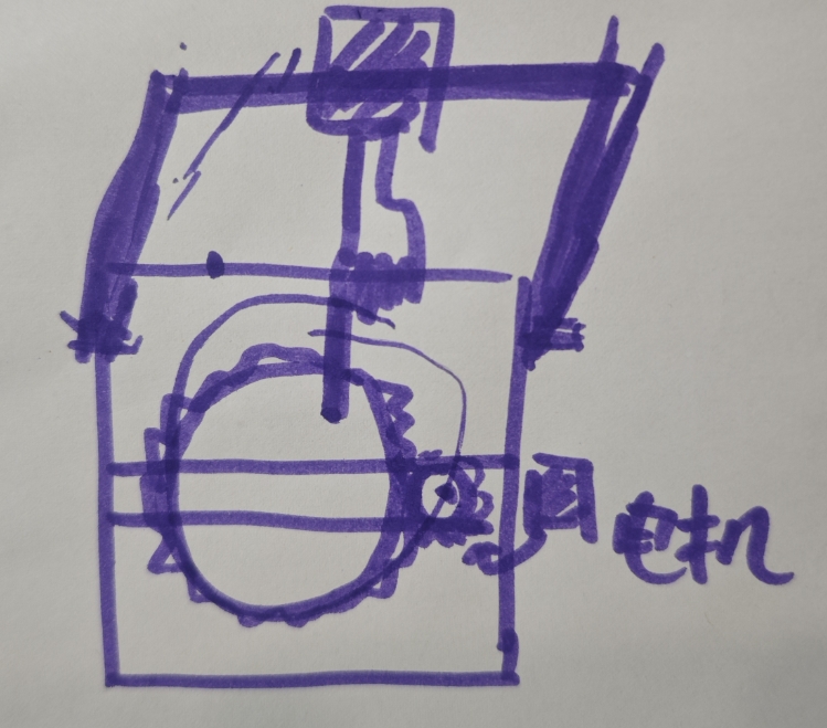
2 Lucky Wheel Selector / Topic Spinner
Function Overview
This is a mechanical structure with a rotating wheel, driven by a stepper motor. Wherever the wheel stops, it selects a student, a question, a group task, etc. It can be used for:
Random question selection
Group assignments
Classroom games or prizes
Choosing duty students
Function Overview
No.
Item
Quantity
Specification / Description
2
Stepper Motor
2
Used to rotate the wheel & Horizontally Moving Finger Mechanism
2
Stepper Motor Driver (A4988)
1
Controls the motor via Arduino
3
Arduino UNO Board
1
Main controller of the system
4
Connectors (3D Printed)
1
Attach the finger model to the sliding rail
5
Gear Wheel (2D Laser Cut)
2
Spinning wheel for random selection
6
Timing Belt (optional)
1
Use of Sliding Rails
7
Power Supply(12V|1A) / USB Cable
1
Provides power to motor and Arduino
8
Push Button
1
Starts the wheel spinning
9
Screws / Nuts / Connectors
Varies
To secure and assemble components
10
Color Labels / Sticker Paper
Varies
For writing names or tasks
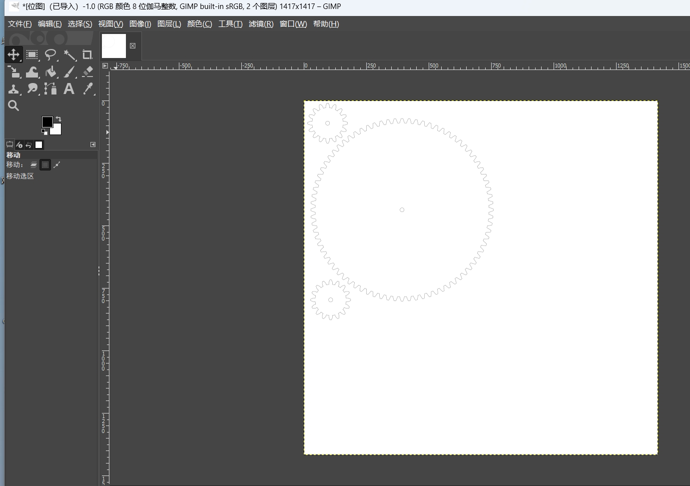
3 Computer Aided Design (CAD)
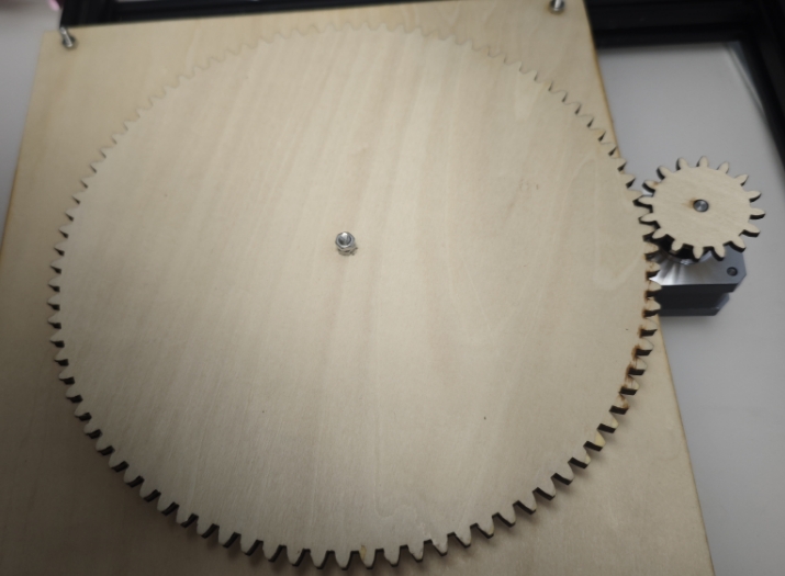
2D Gears & Laser Cutting
In this section, 2D gear designs were created using GIMP. The designs were exported as SVG files.
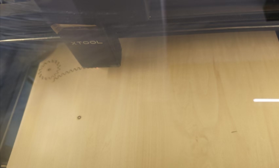
Use laser cutting to cut the gears.
Complete the gear fabrication.
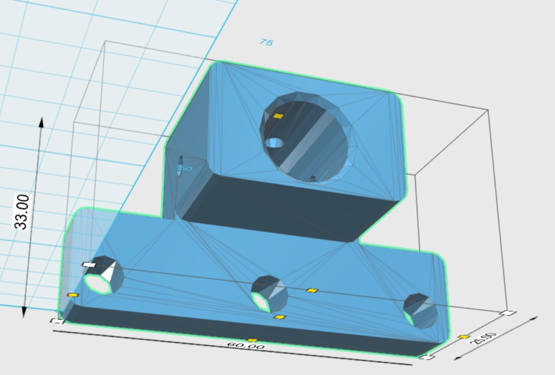
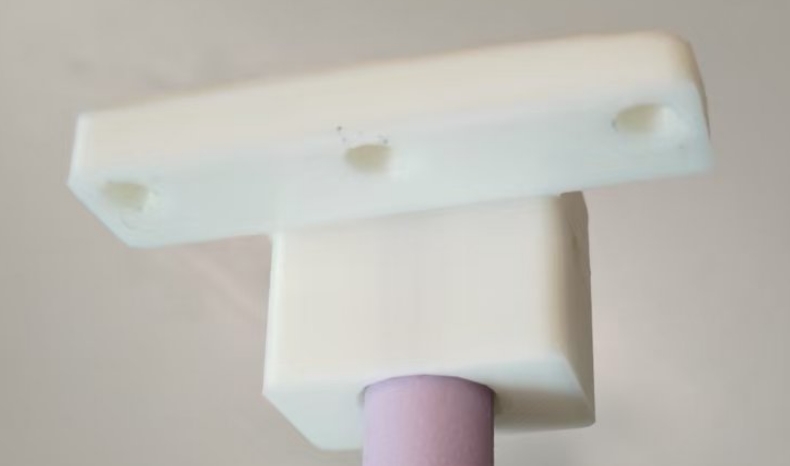
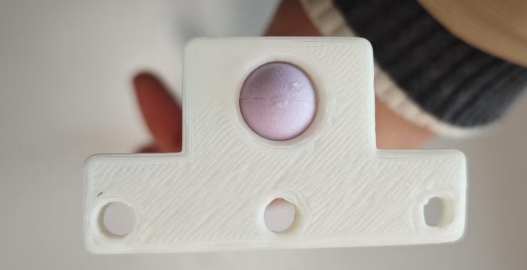
3D Connectors & 3D Printing
Custom 3D connectors were designed to assemble the gear system components.
These parts were modeled in 3D CAD software.
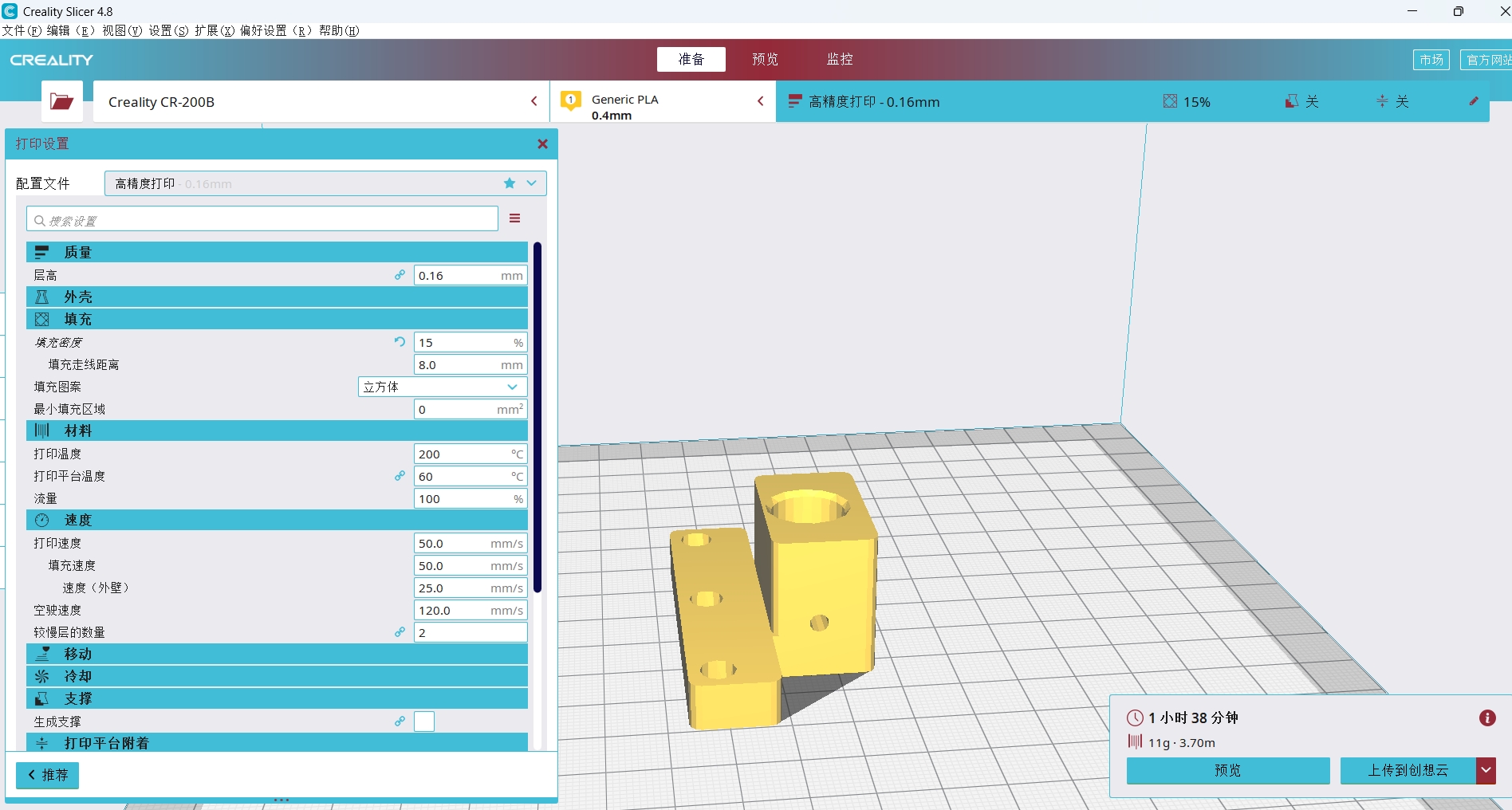
These parts were printed using a 3D printer(Creality ).
Assemble the connector and the finger lever together.
The connectors ensure structural stability and precise alignment of the moving parts.
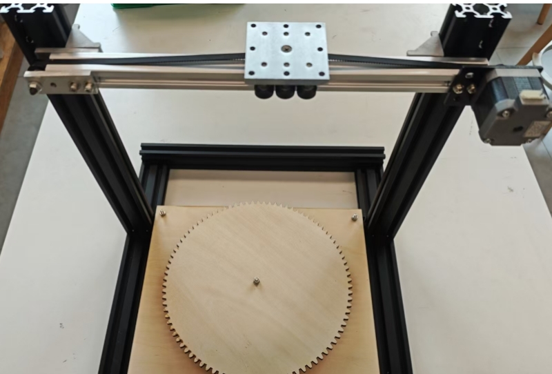
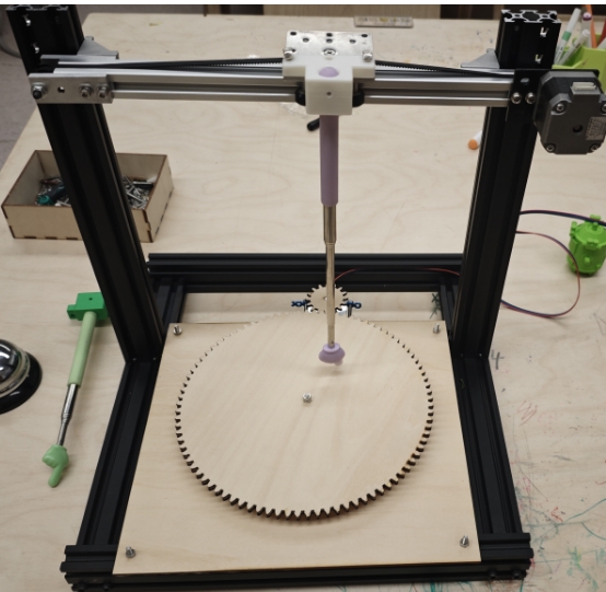
4 Machine Assembly
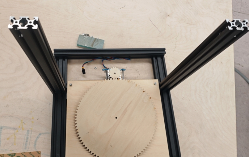
01 Assemble the gears
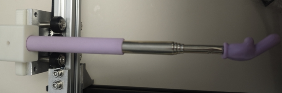
02 Install the X-axis motor
03 Connect the finger model using connectors
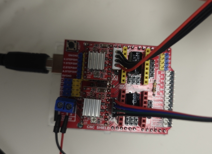
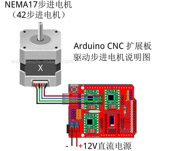
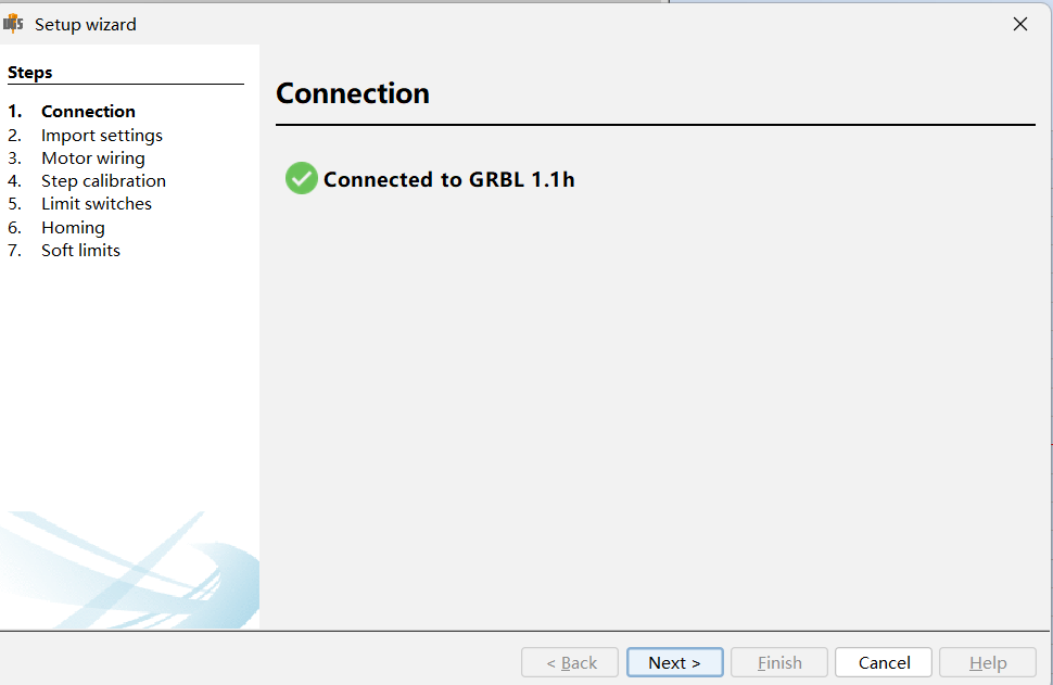
5 Control Unit
Control Unit, responsible for receiving, processing, and sending instructions. Key components: Arduino Uno board, expansion board, 4 corresponding chips, 3 female-to-female jumper wires, and a 12V power supply.
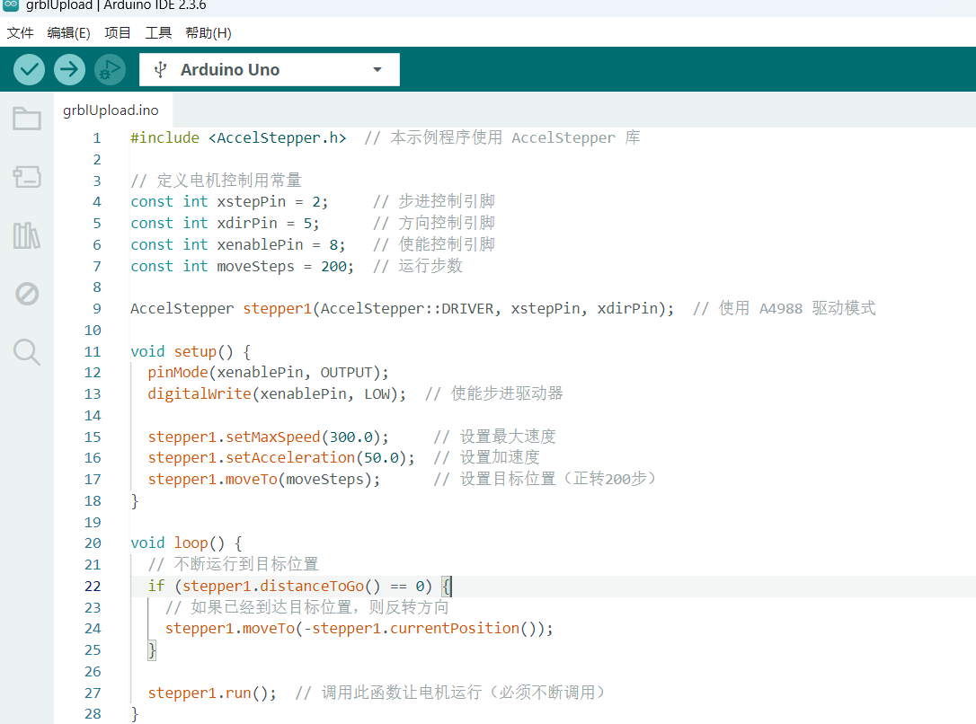
2.Connect the motor; do not close the Arduino IDE.
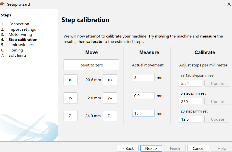
3.Adjust the motor speed according to the step angle of the stepper motor.
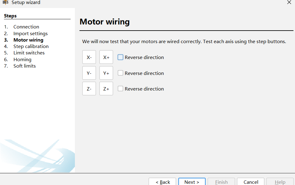
After connecting the motor, perform a test.
Turntable motor test.
Motor test in the horizontal X-axis direction.
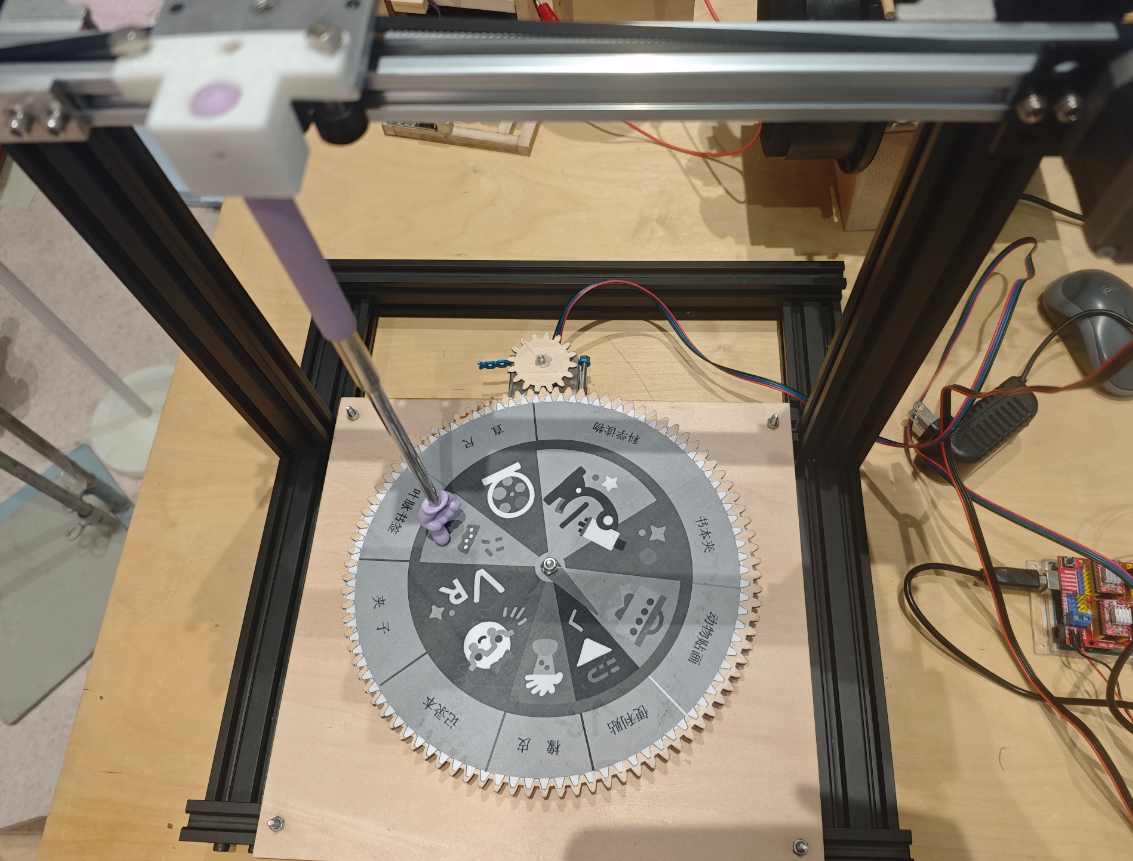
6 Machine Testing and Operation
<
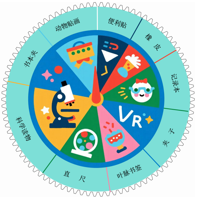
Automatic Lucky Draw Wheel
Complete the design of the prize wheel cards. Students can use a robotic arm to randomly draw their own rewards. The wheel cards can also be designed with different themes, such as science quizzes or classroom simulations.
Attach cards to the top of the wheel
Run the test: the turntable moves 50 mm, the shaft moves 30 mm, pause for 5 s, then the X-axis returns to the home position in the reverse direction.
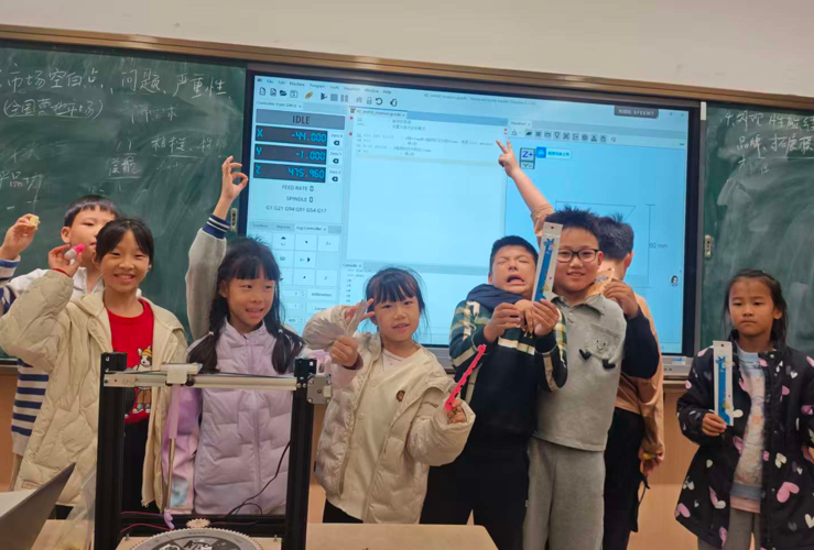
Students experience the lucky wheel.
The children received prizes, and they were all very happy.