Exploring output devices this week showed me how important feedback is in user experience. Whether it's lights, sounds, or displays, output devices bring the system to life by communicating information clearly and effectively.
Learning Objectives
Group Assignment
Measure the power consumption of an output device.
Individual Assignment
Add an output device to a microcontroller board you've designed and program it to do something.
Learning highlights
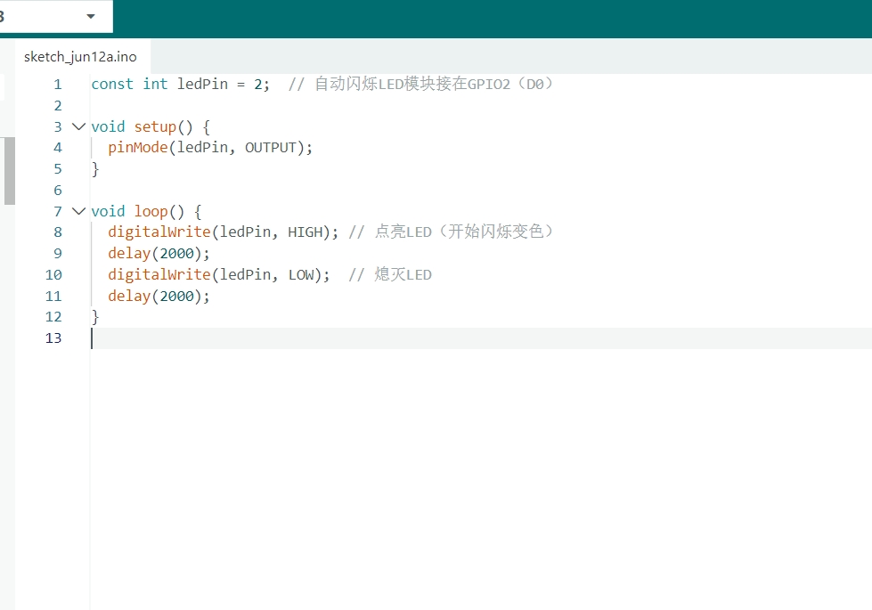
Output device example
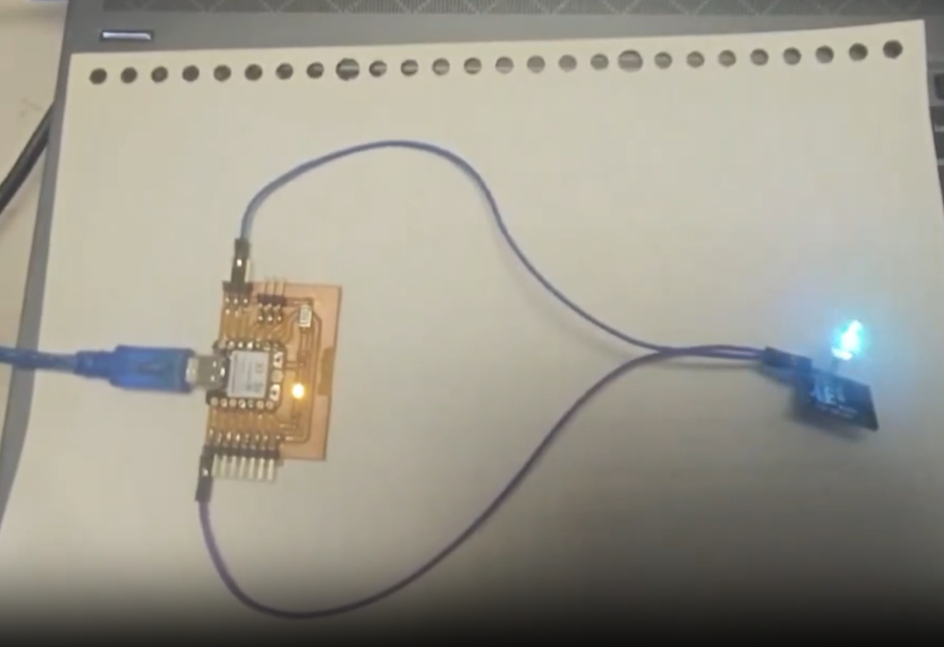
Using the Seeed Studio XIAO ESP32-C3 to control a multi-color LED
Group Assignment
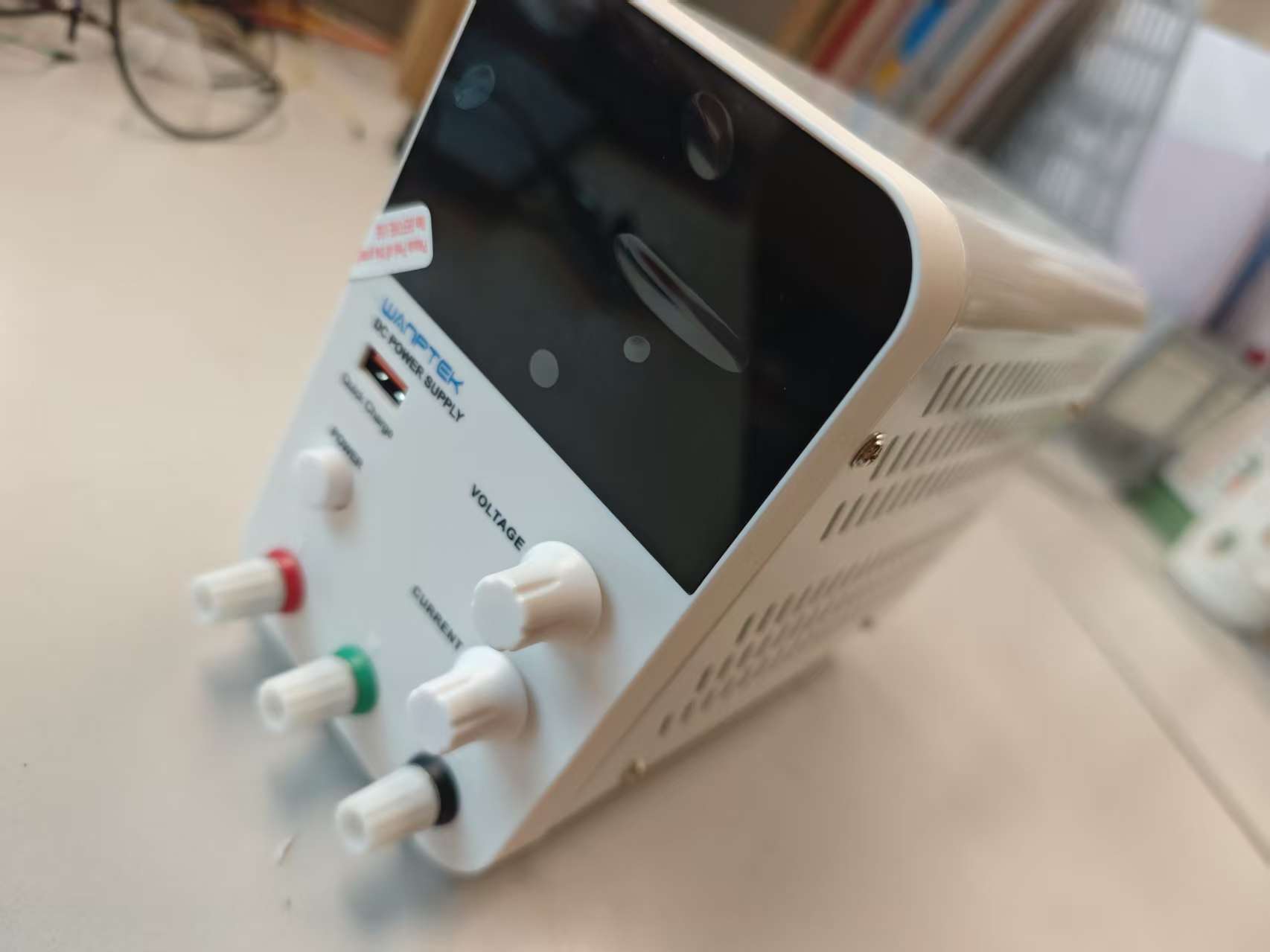
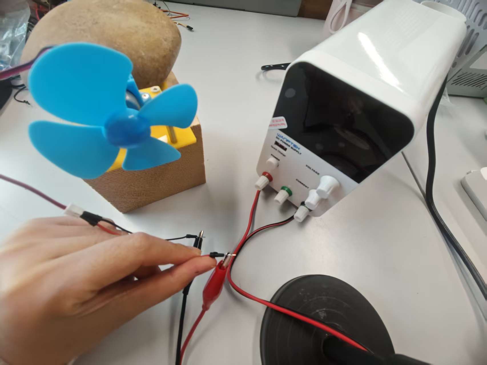
We used a DC power supply to measure the DC motor’s power consumption. The supply operates in two modes: constant voltage (CV) and constant current (CC). The operating mode depends on the voltage and current settings as well as the characteristics of the connected load.
WANPTEK GPS605D DC POWER SUPPLY
Input voltage:AC 220V 50Hz
Output voltage:0 ~ 60V
Output current:0 ~5A
Voltage resolution:10mV
Current resolution:1mA
Indicator Meter:
Voltage display precision: +-(0.5% of rdg + 2 digits).
Current display precision: +-(0.5% of rdg + 2 digits)
DDC Power Supply Test for DC Motor Experiment, the connection is as follows:
Test video
Observation: We set the maximum voltage to 2V and used the constant current (CC) mode to observe the changes in voltage and the motor’s movement. The larger the current, the higher the voltage; conversely, the smaller the current, the lower the voltage. According to the formula P = I × V, the power consumption of the DC motor decreases accordingly. When the current is less than 0.05A, the motor stops running.
Individual Assignment
1 Introduction
1.1 LED Display Introduction
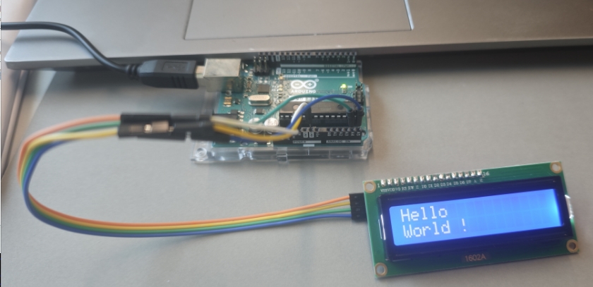
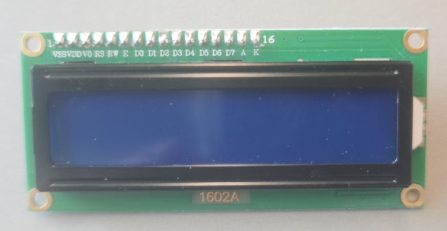
An LED display is a module designed to display letters, numbers, and symbols. It is widely used in industrial applications such as digital clocks and temperature displays.I am using an I2C 1602A LCD.
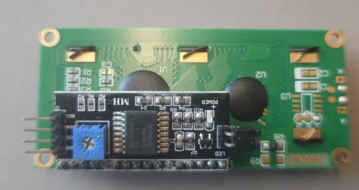
Note: If the LCD backlight is too dim, adjust the blue potentiometer on the back of the LCD module.
1.2 Working Principle of I2C 1602A LCD
The I2c 1602 LCD is a common 16×2 character liquid crystal display often used in embedded systems such as Arduino or microcontroller projects. It can display 2 rows with up to 16 characters per row. The common interface methods include parallel interface (4-bit or 8-bit mode) and I2C interface (via the PCF8574 expansion module).
1.3 How to Use an LED Display to Show "Hello World!"
Components Required: Arduino board, LED display module, and jumper wires.
Start → Initialize → Display "Hello World!" on the LED screen → End
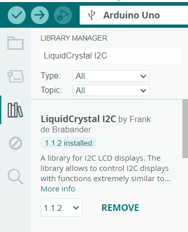
1.3.1 Install Library
Open the Library Manager in Arduino IDE (Ctrl + Shift + I).
Search for LiquidCrystal I2C.
Install the latest version.
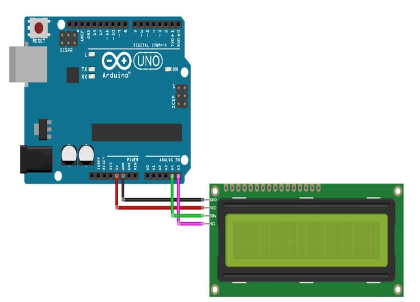
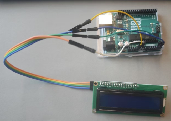
1.3.2 Connecting I2C LCD to Arduino
LCD Pin
Arduino Uno Pin
VCC
5V
GND
GND
SDA
A4
SCL
A5
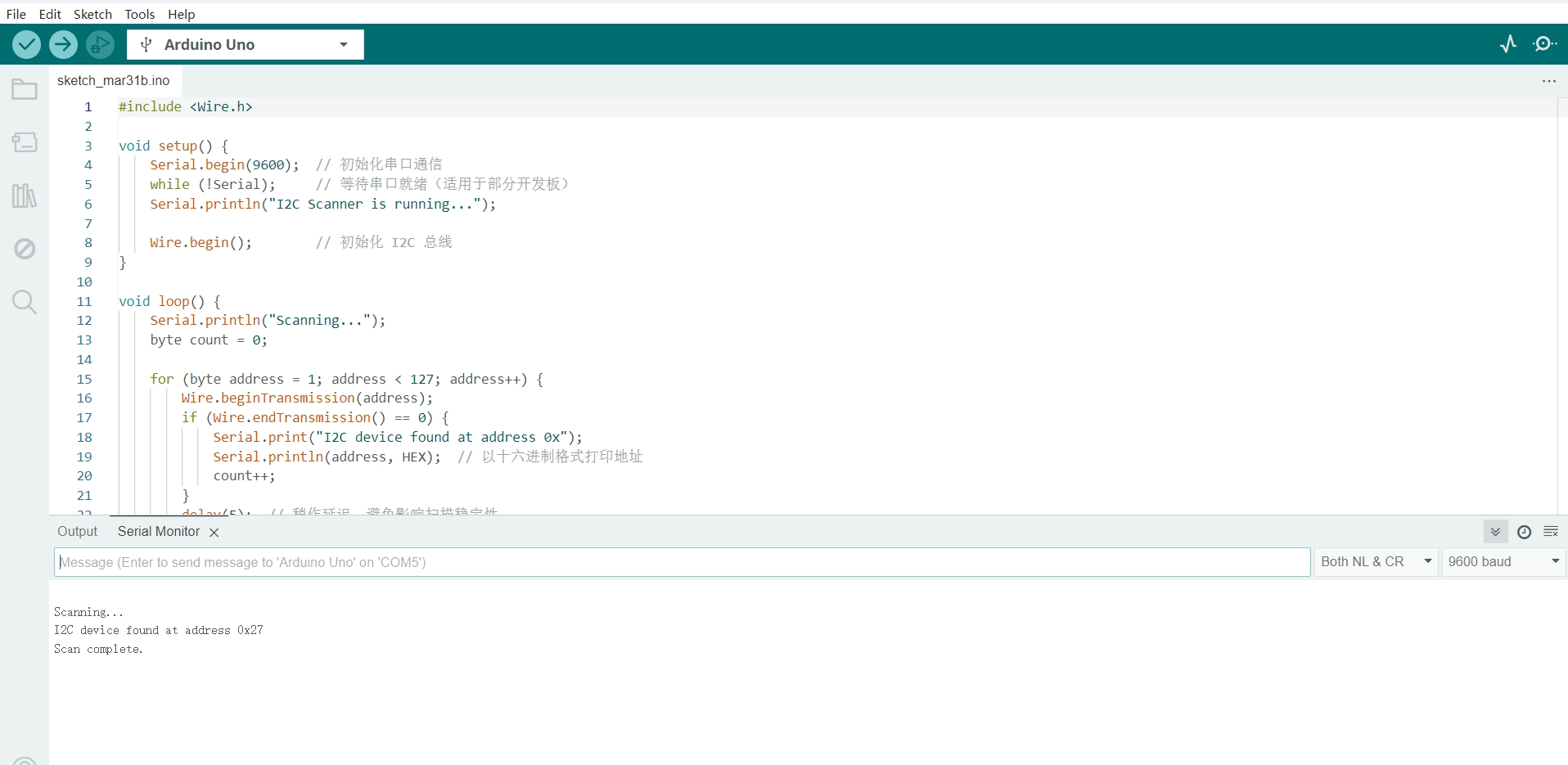
1.4 I2C Address Scanning
The first time testing the code, the display did not show any content, so I used the following code to check the I2C Address.
#include <Wire.h>

void setup() {
    Serial.begin(9600);
    while (!Serial);
    Serial.println("I2C Scanner is running...");
    Wire.begin();
}

void loop() {
    Serial.println("Scanning...");
    byte count = 0;
    for (byte address = 1; address < 127; address++) {
        Wire.beginTransmission(address);
        if (Wire.endTransmission() == 0) {
            Serial.print("I2C device found at address 0x");
            Serial.println(address, HEX);
            count++;
        }
        delay(5);
    }
    if (count == 0) Serial.println("No I2C devices found!");
    Serial.println("Scan complete.\n");
    delay(5000);}
My Troubleshooting Steps
Ensure lcd.backlight(); is called to turn on the display.
Adjust the contrast using the potentiometer on the I2C board.
Check all wiring connections (SDA/A4, SCL/A5, VCC 5V).
Test another LCD module or I2C adapter if the issue persists.
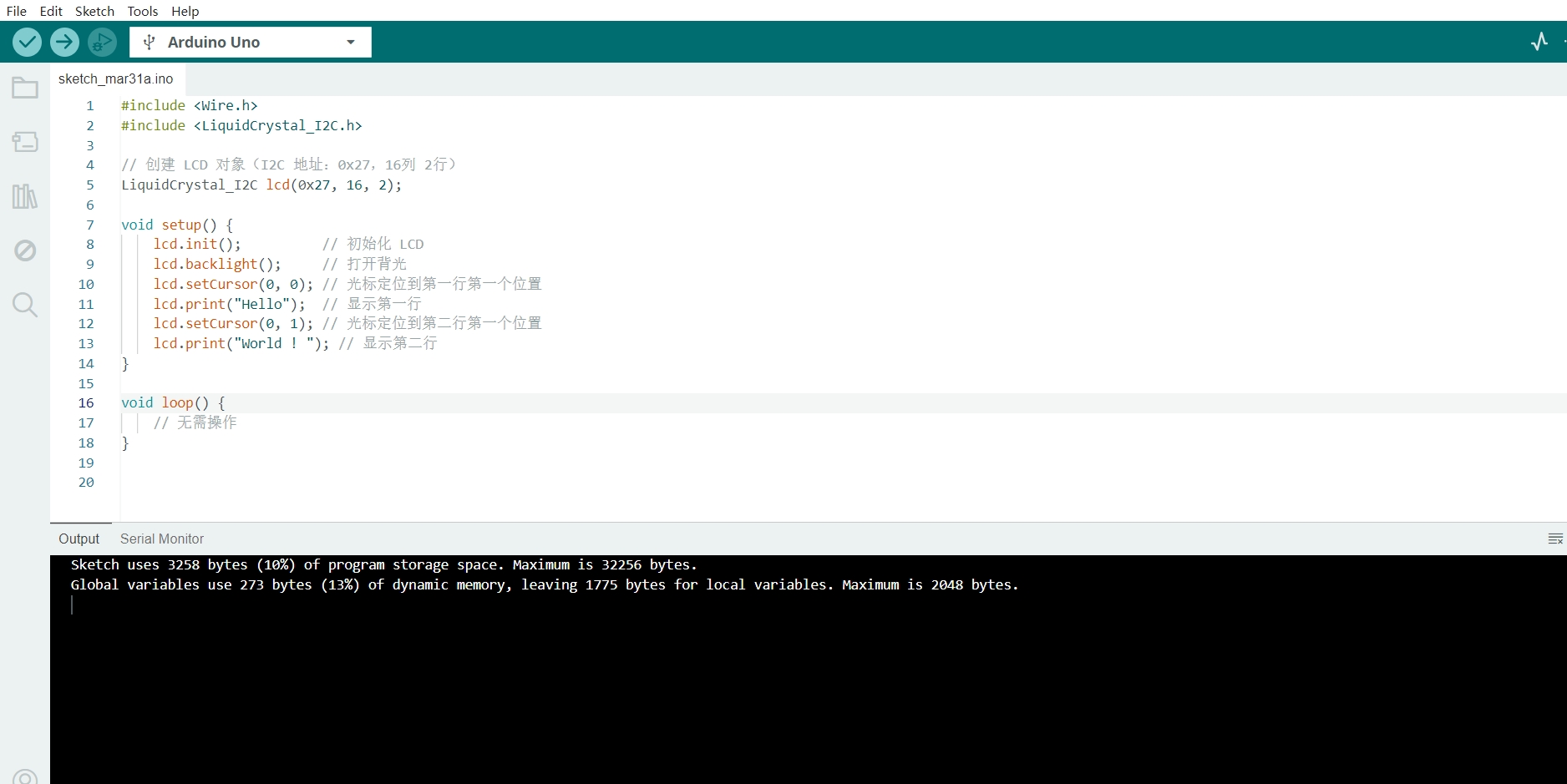
1.5 LCD Display Test Code
The correct I2C address is found(0x27), use the following test code:
Unfortunately,there was still no display content. I continued troubleshooting and found that the contrast needed to be adjusted. Finally, the test was completed.
Adjusting the Contrast
Problem:The LCD contrast might be too low, causing the characters to be unclear.
RotateRotate the potentiometer (blue square) on the back of the I2C module and gradually adjust the contrast until the characters are clearly visible.
The test was finally successful!
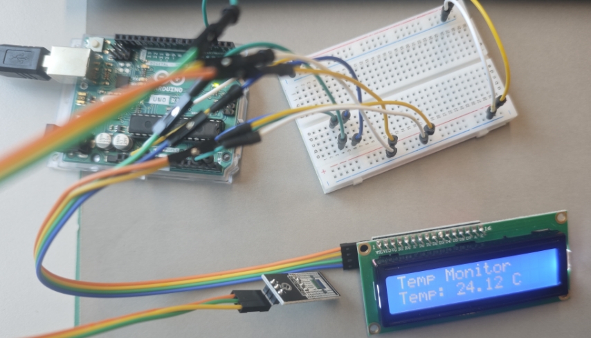
2 Electronic Thermometer
This device uses the DS18B20 sensor as the temperature input and an I2C 1602 LCD as the output display.
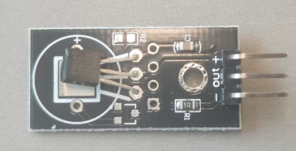
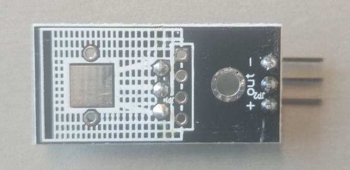
2.1 DS18B20 Temperature Sensor
2.1.1 Introduction
DS18B20 is a common digital temperature sensor that uses a unique single-wire interface. Compared to analog temperature sensors, it is more functional, simple in hardware, easy to expand, and highly resistant to interference.
2.1.2 Specifications
Feature
Specification
Power Supply
DC 5V
Temperature Range
-55 to +125℃
Communication Interface
1-Wire
Accuracy
±0.5℃
Resolution
9-12 bits adjustable
2.2 Working Principle
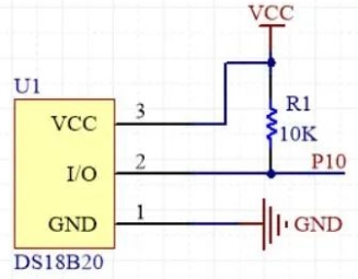
2.2.1 Circuit Diagram
The pin configuration is as follows:
Pin
Description
VCC
Power Supply (5V)
GND
Ground
I/O
Data Line
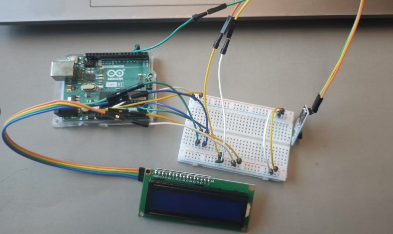
2.2.2 Circuit Connections
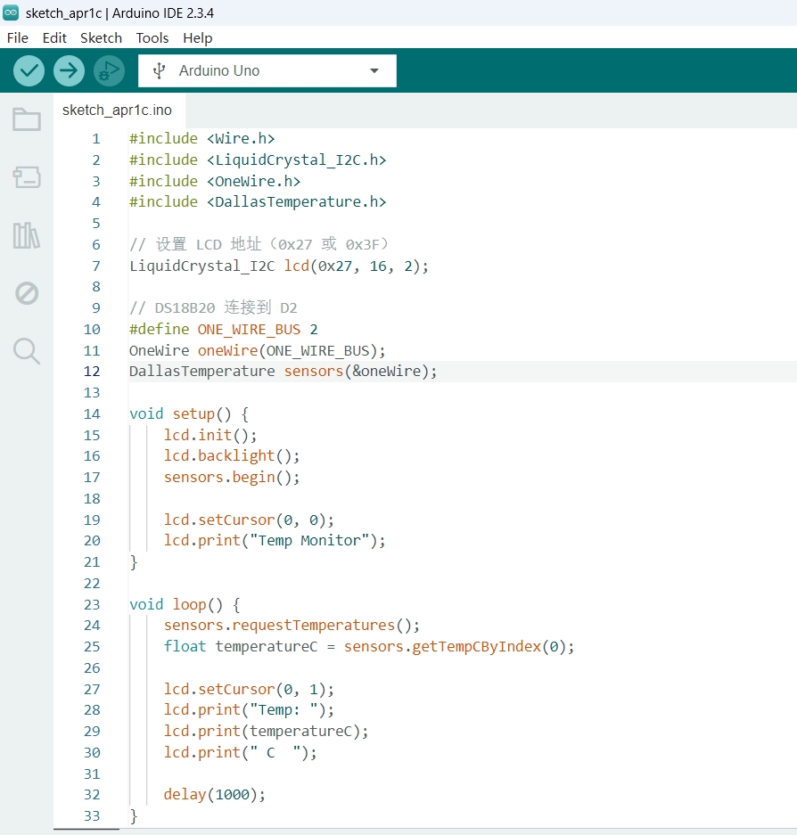
2.3 Coding and Operation
The following Arduino code reads temperature from the DS18B20 sensor and displays it on an I2C 1602 LCD:
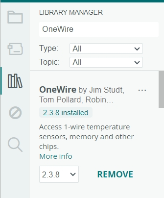
2.3.1 Install OneWire and DallasTemperature Libraries
In the search box, enter "One Wire," find the OneWire library developed by Paul Stoffregen, and install it.
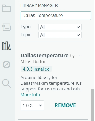
Then, in the search box, enter "Dallas Temperature," find the Dallas Temperature library developed by Miles Burton, and install it.
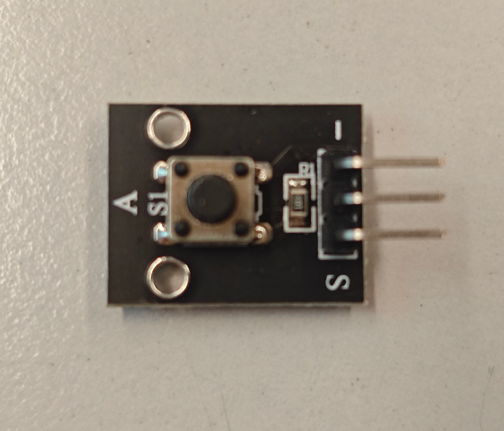
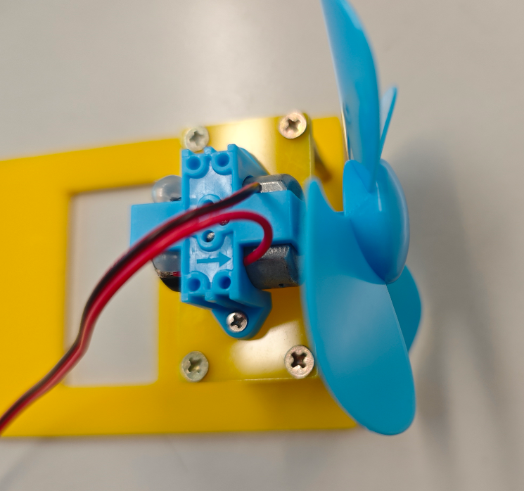
Use one button module and one DC motor to build a small fan. The button module is used to control the fan’s speed and select different speed levels.
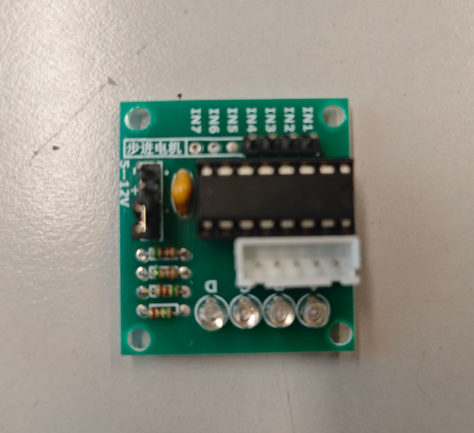
3.1 ULN2003 Motor Driver
The ULN2003 motor driver is a high-voltage, high-current Darlington transistor array commonly used to drive stepper motors, DC motors, and relays. It contains seven NPN Darlington pairs, each capable of driving up to 500 mA and withstanding 50 V.
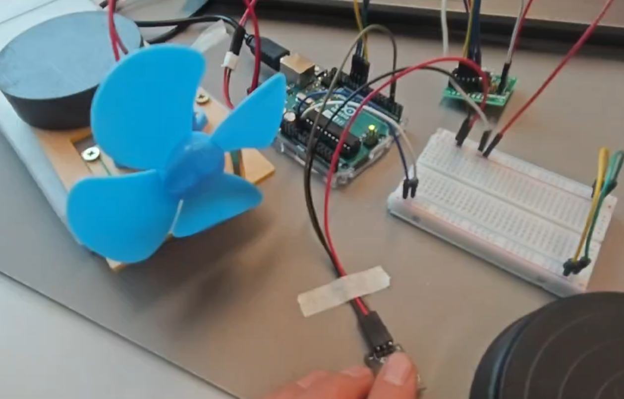
3.2 Circuit Connection
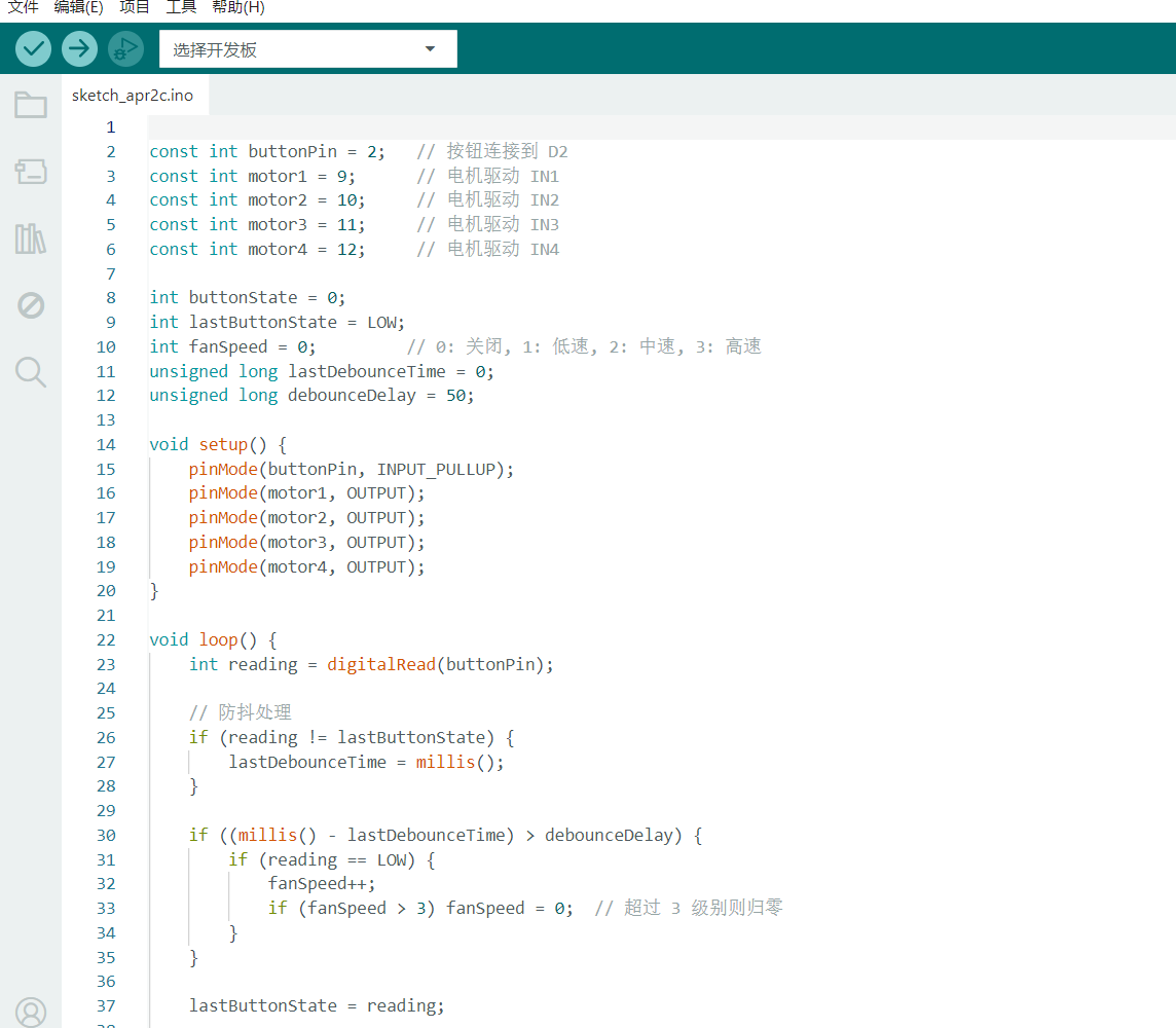
3.3 Coding and Operation
code
test
4.1 Rainbow LED blinking
Using the Seeed Studio XIAO ESP32-C3 to control a multi-color LED