Exploring output devices this week showed me how important feedback is in user experience. Whether it's lights, sounds, or displays, output devices bring the system to life by communicating information clearly and effectively.
Learning Objectives
Group Assignment
Probe an input device(s)'s analog levels and digital signals.
Individual Assignment
Measure something: add a sensor to a microcontroller board that you have designed and read it.
Learning highlights
Digital Hall Sensor & Noise Alarm System
Group Assignment
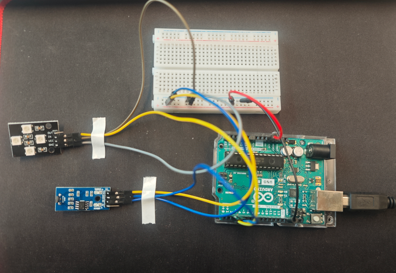
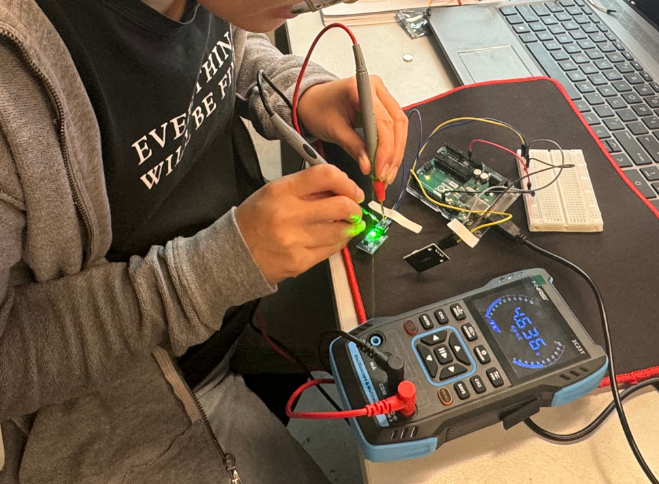
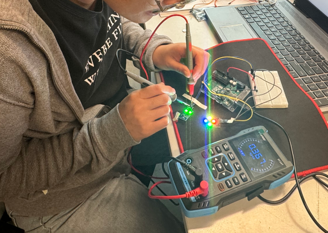
We used a multimeter to detect the digital signal of the Hall sensor. (The connection method and code for controlling the LED with the Hall sensor are detailed below.) We tested the voltage difference transmitted to the development board when the Hall sensor was exposed to a magnet and when no magnet was present.
Set the multimeter to DC voltage mode.
Black probe connected to GND.
Red probe connected to the Hall sensor’s DO pin.
Voltage Variation
No magnet nearby: Most modules output High level ≈ 4.436V on DO
Magnet nearby: DO outputs Low level ≈ 0.367V
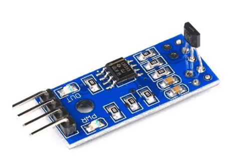
1 Digital Hall Sensor
A Digital Hall Sensor is a magnetic field sensor based on the Hall effect.
It can detect the presence or absence of a magnetic field and outputs a digital signal (HIGH or LOW).
It is commonly used for position detection, speed measurement, and switch control.
1.1 Basic Principle
Hall Effect: When current flows through a semiconductor material in the presence of a perpendicular magnetic field, a Hall voltage is generated across the material.
Digital Hall Sensor: It integrates an amplifier circuit and a Schmitt trigger.
When the magnetic field strength reaches a certain threshold, the output flips between HIGH and LOW.
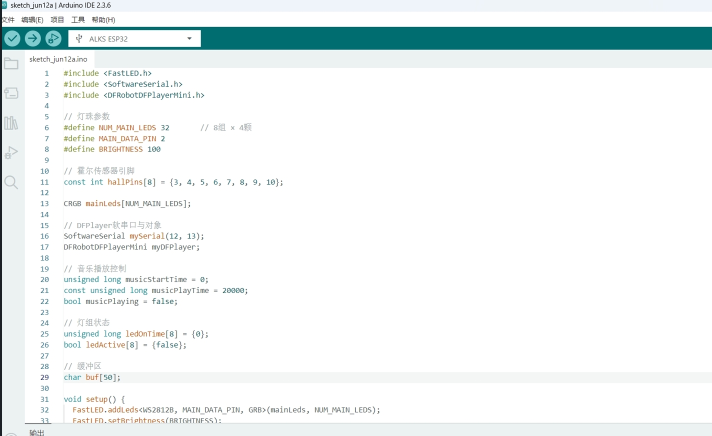
When a student puts their apple near the Hall sensor, the LED lights up and a happy “Great job!” plays.
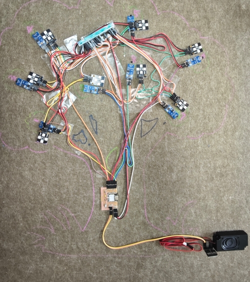
Connection layout
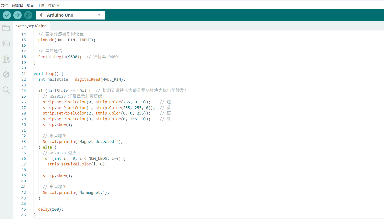
code
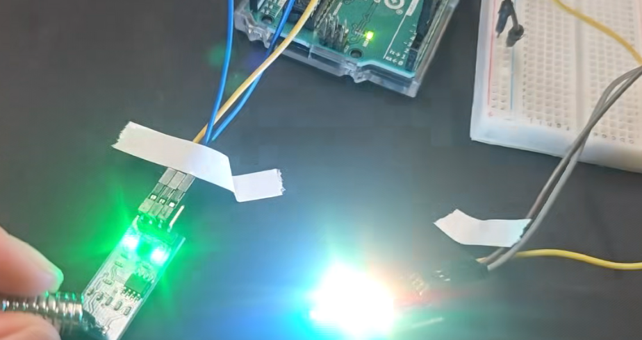
Test
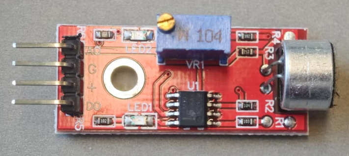
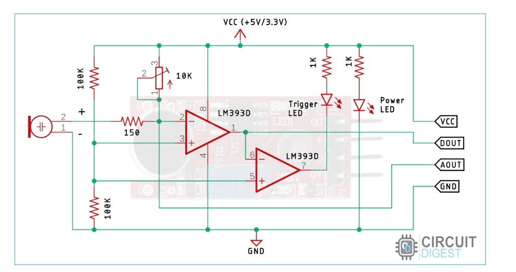
3 Sound Sensor
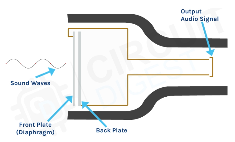
A sound sensor is a component that receives sound waves and converts them into electrical signals. It works like a microphone to detect the sound intensity in the surrounding environment. It has various applications, such as noise monitoring, voice control, and security alarms.
Component
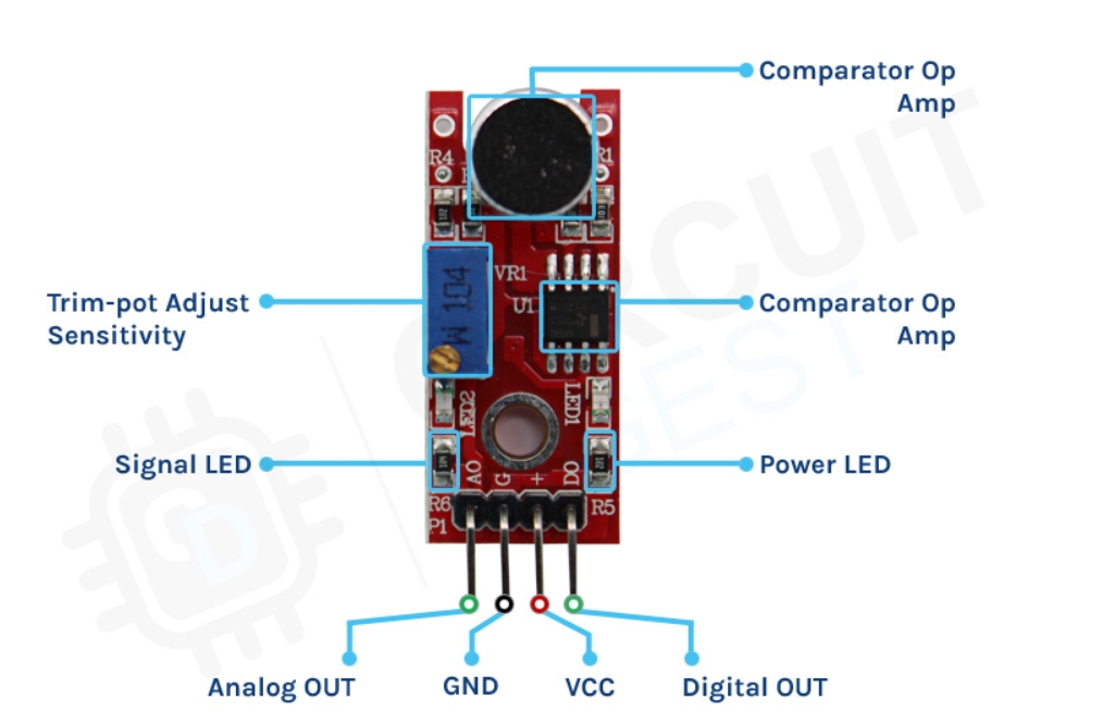
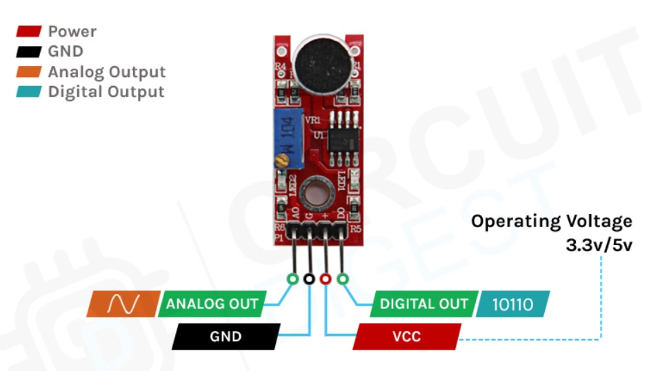
3.1 Sound Sensor Pins
Pin
Function
A0
Analog Output (Range 0~1023)
VCC
Power Input (5V)
G
Ground
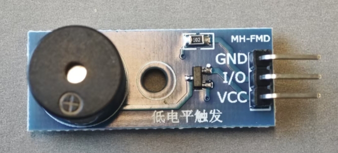
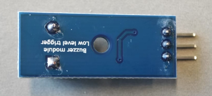
3.2 Buzzer
A buzzer is an audio signaling device that can be controlled by electrical signals to produce sounds of different frequencies and intensities. It is commonly used for alarms, notifications, and sound feedback applications.
Passive Buzzer Pins
Pin
Function
VCC
Power Inpuy (5V)
I\O
Connected to D9 via tone() control
GND
Ground
Active Buzzer & Passive Buzzer
Feature
Active Buzzer
Passive Buzzer
Internal Oscillator
Built-in Oscillator
Requires PWM
Control Method
Simply turn on/off with HIGH/LOW signal
Requires PWM signal for sound generation. Requires tone()
Sound Types
Fixed frequency
Can produce multiple tones and melodies
Sound Modulation
Fixed Frequency
Can Play Melodies
Wiring
Directly Connect to Arduino
Requires PWM Control
Common Uses
Alarms, simple notifications
Music tones, sound effects
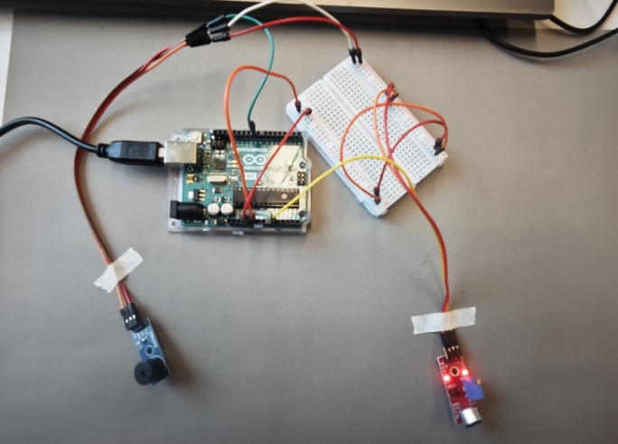
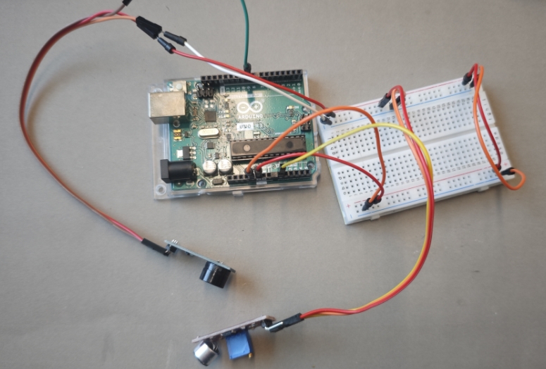
3.3 Component Introduction
Main Hardware
Component
Function
Arduino UNO
Controls the entire system
Sound Sensor
Detects sound intensity in the environment
Passive Buzzer
Generates alarm sounds
Jumper Wires
Connects components
Breadboard
Used for circuit assembly
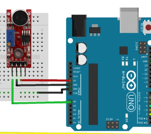
3.4 Circuit Connections
3.1 Connecting the Sound Sensor
Sound Sensor
Arduino
A0
A0
VCC
5V
G
GND
3.5 Connecting the Passive Buzzer
Passive Buzzer
Arduino
VCC
5V
I/O
D9
GND
GND
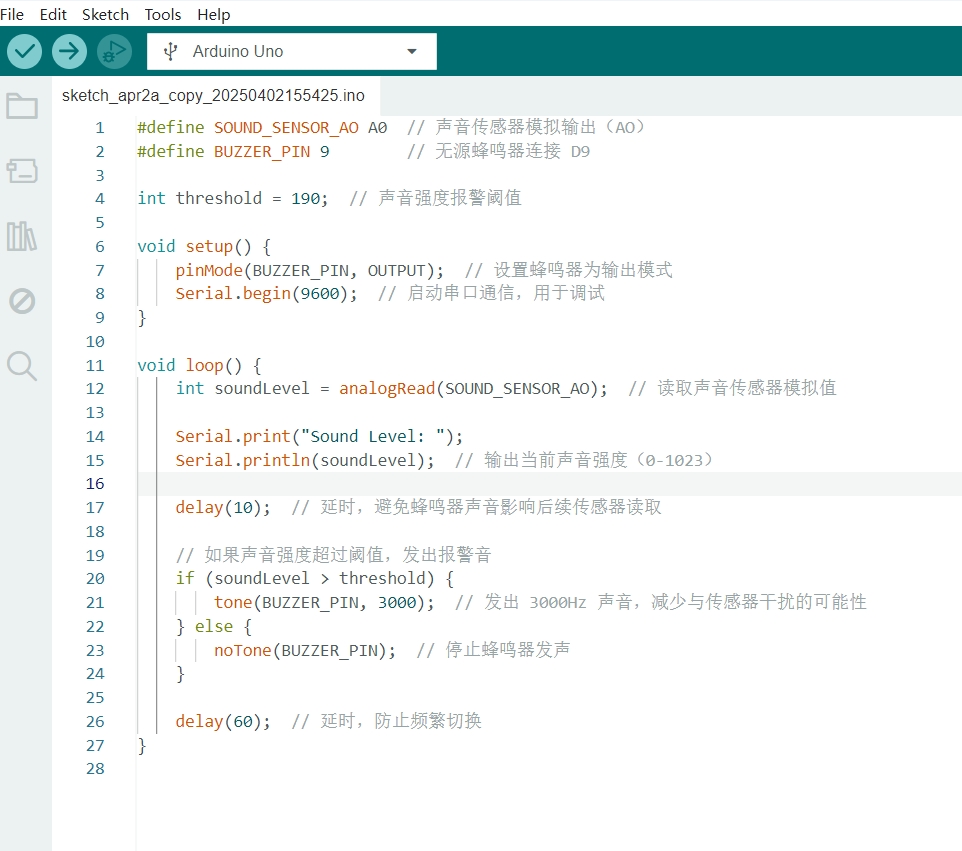
3.6 Arduino Code
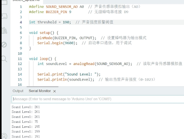
3.7 Compilation & Testing
Upload the code and test it by monitoring sound intensity in the Serial Monitor.