This week, I started learning computer-controlled machining. I was excited because I could design a multifunctional tall stand that can serve as a plant stand to help organize cluttered spaces and add a touch of nature, or as a computer desk to hold a computer for teaching or presentations.
Learning Objectives
Group assignment:
Complete your lab's safety training
Test runout, alignment, fixturing, speeds, feeds, materials and toolpaths for your machine
Individual assignment:
Make (design+mill+assemble) something big
Learning highlights
Multifunctional tall stand
Group Assignment
1. Introduction to CNC
1.1 What is CNC?
CNC (Computer Numerical Control) is a technology that uses computers to control machines through numerical data. It belongs to subtractive manufacturing. The machine follows G-code commands, which control tool movement and actions. Once programmed, the machine can operate autonomously, reducing manual intervention and improving efficiency.
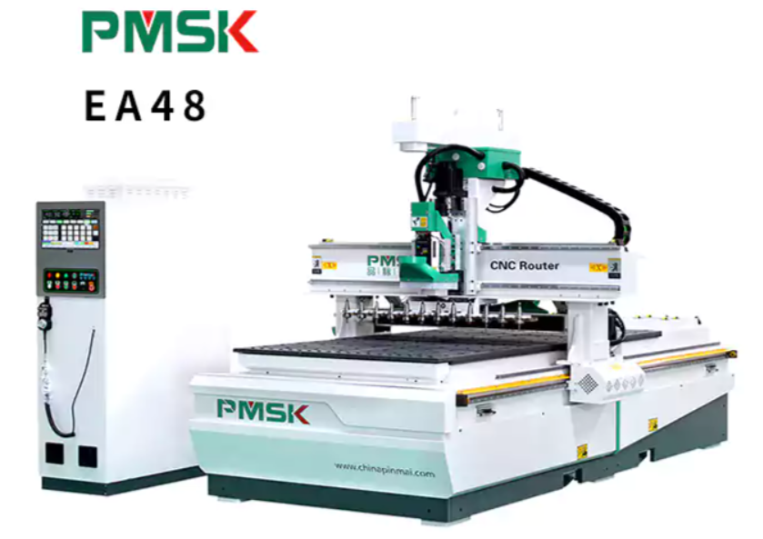
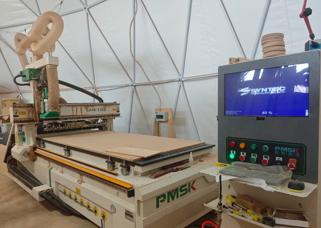
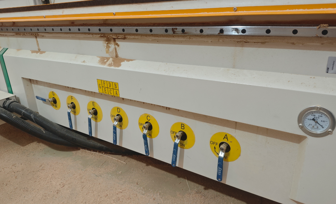
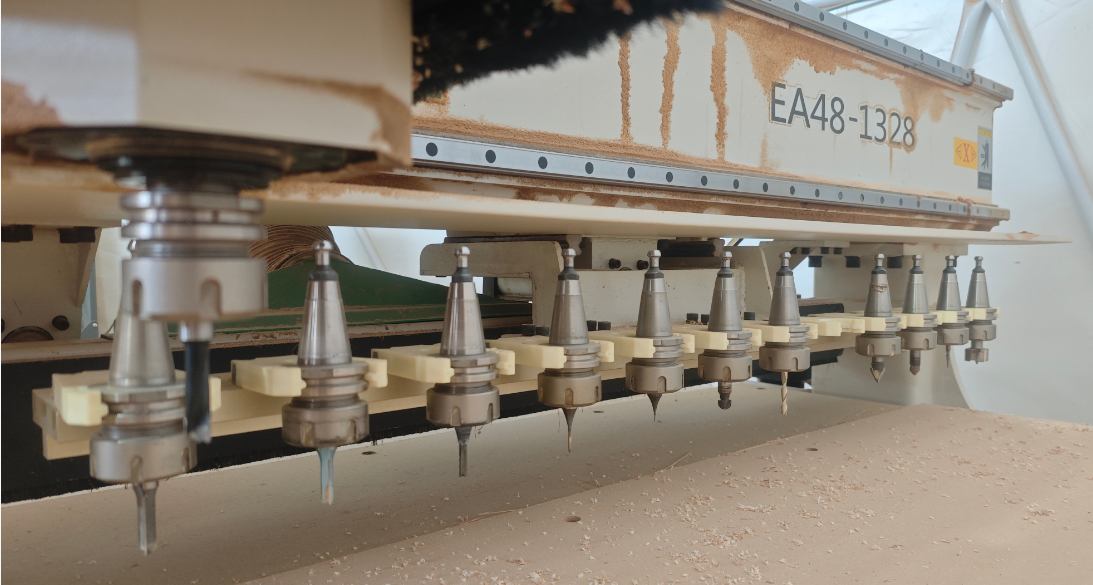
1.2 PMSK/EA48-1328
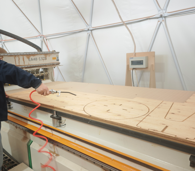
I used the PMSK/EA48-1328 to cut my furniture.Control operation using the SYNTEC system.
Item
Typical Values / Description
Work Area / Table
1300 × 2800 mm
Spindle / Tool
Usually 9.0 kW air-cooled spindle + ATC tool changer
Tool Magazine Capacity
Optional 4 / 6 / 8 / 12 / 16 tools
Control System
Common SYNTEC controller
Spindle Speed
Up to 20,000 rpm
Transmission
X/Y: rack & pinion, Z: ball screw
Speed Performance
Max rapid traverse ~80 m/min, working speed ~25 m/min
Clamping / Holding
Double-layer PVC porous vacuum table for sheet fixation
Additional Features
Dust extraction, automatic lubrication system
The PMSK/EA48-1328 vacuum table automatically clamps materials, and the ATC enables automatic tool changing.
1.3 Important Parameters
For hardwoods: different materials require different endmills and cutting speeds. Soft materials can use faster feed rates; hard materials require slower feeds and higher spindle speeds. For example, use flat-end mills for roughing and ball-end mills for finishing on soft plywood.
Drill: Only drills down, does not cut edges
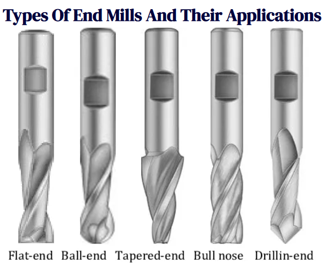
An end mill is an industrial cutting tool mainly used for milling. Its tip and sides have multiple cutting edges, allowing vertical (end milling) or horizontal (side milling) cuts.
End mill types: flat-end, ball-end, tapered-end, bull-nose, drilling-end
Parameter
Symbol
Meaning
Spindle Speed
n (rpm)
Rotations per minute of the tool
Cutting Speed
vc (m/min)
Relative speed of the tool edge over the workpiece surface
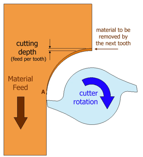
Feed per Tooth
fz (mm/tooth)
Distance each tooth cuts per rotation
Feed Rate
vf (mm/min)
Linear speed of the tool
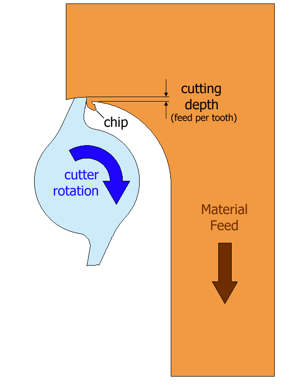
Climb or Down Milling
Tool rotation direction is the same as feed direction.
Cut chip thickness decreases from start to end, discharged behind the cutting path.
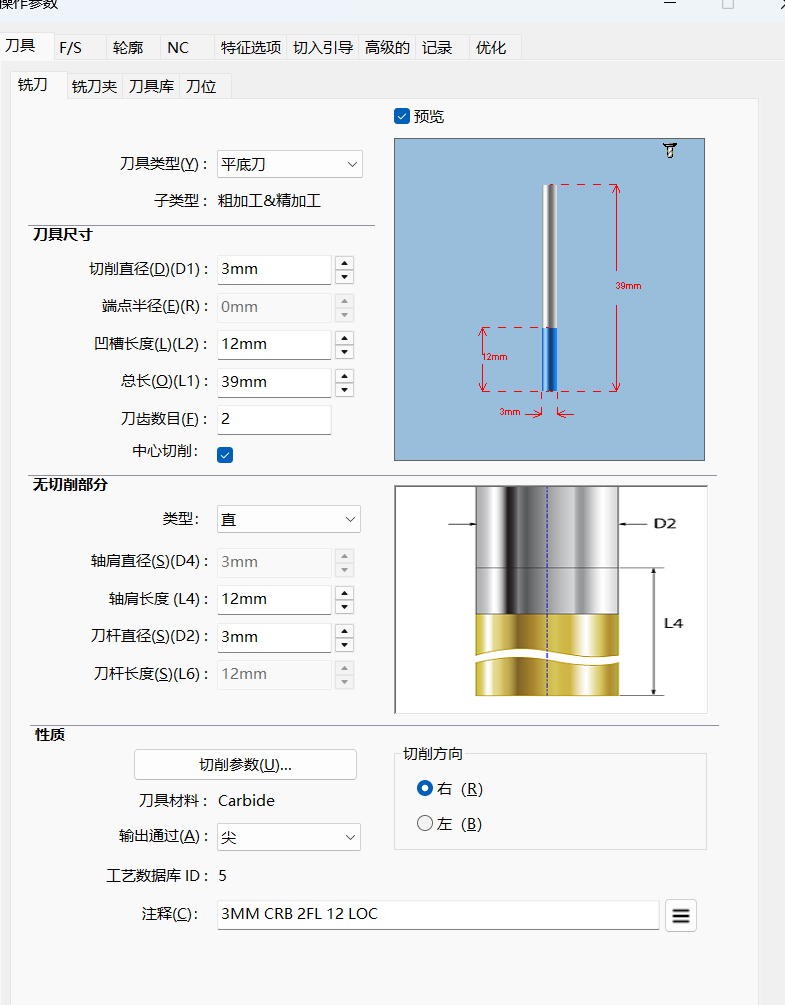
Tool Diameter: affects tool strength and cutting speed. Larger diameters provide higher rigidity and reduce deformation risk.
Shank Diameter: connection part of the tool to the holder. Usually same as tool diameter for rigidity.
Core: inside the tool between cutting edges, provides strength.
Cutting Length: effective length of the tool that can cut, determined by flute depth.
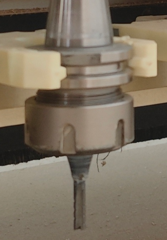
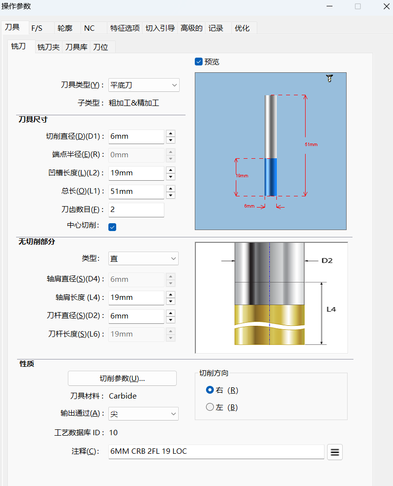
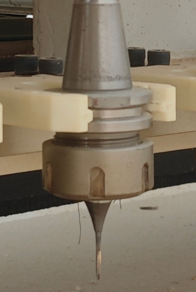
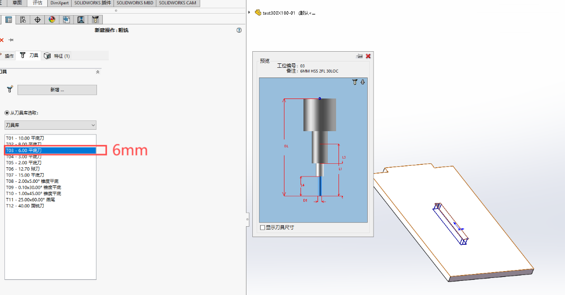
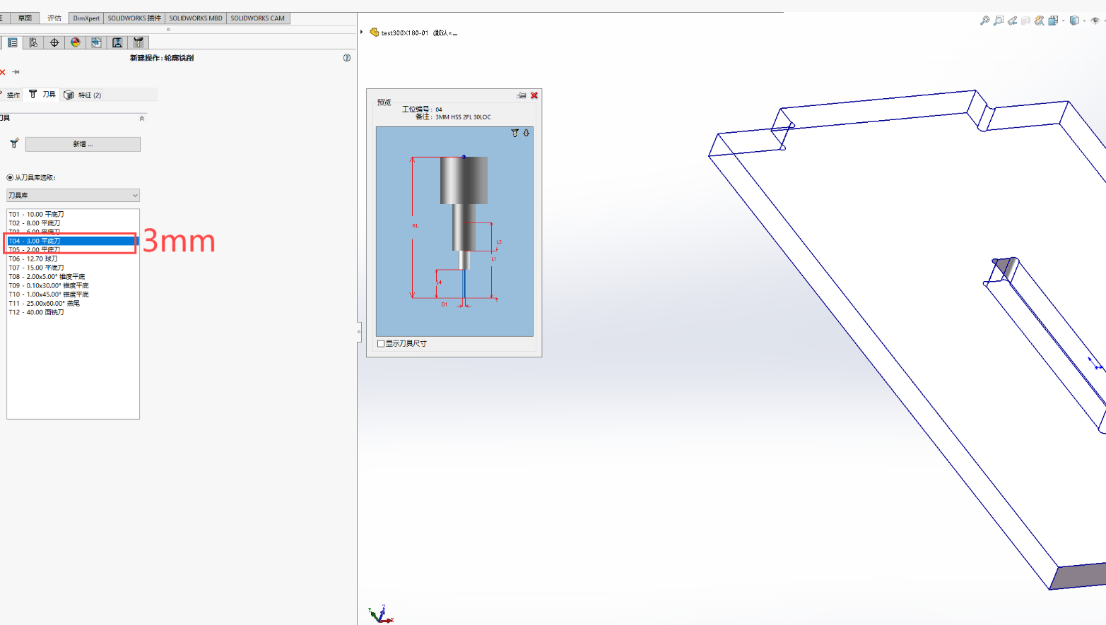
Use two types of end mills: a 6mm end mill for cutting the overall outline, and a 3mm end mill for pocket clearing to create dogbone joints.
6mm end mill
3mm end mill
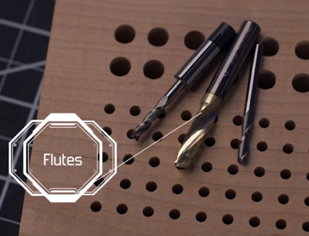
Flutes: Helical grooves along the tool for chip removal, ensuring smooth cutting.
1.4 Safety Notes
Wear proper work clothes and safety shoes; no sandals, heels, or jewelry.
Use ear protection, dust mask, and safety goggles.
Know the location of the emergency stop switch.
Keep all non-operators away from the machine.
Do not enter within 1 meter of the running machine.
Unauthorized personnel must not operate without supervision.
Be aware that rotating tools generate heat and may pose fire hazards.
2. Machine Testing
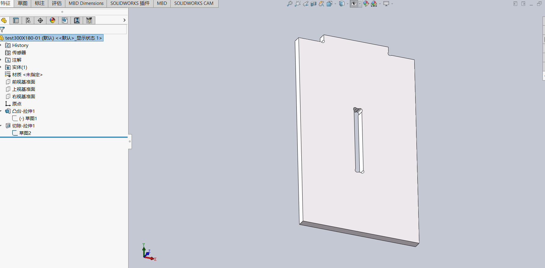
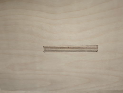
2.1 Design the test piece.
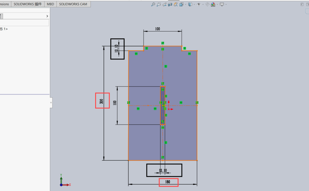
Download and use SOLIDWORKS 2024 to modify and cut the test piece.The test piece measures 300×110 mm.
the basswood board measured 12.2 mm with a vernier caliper.
The machine’s cutting accuracy is 0.1 mm, so the slot width is designed to be 12.1 mm to achieve an interference fit.
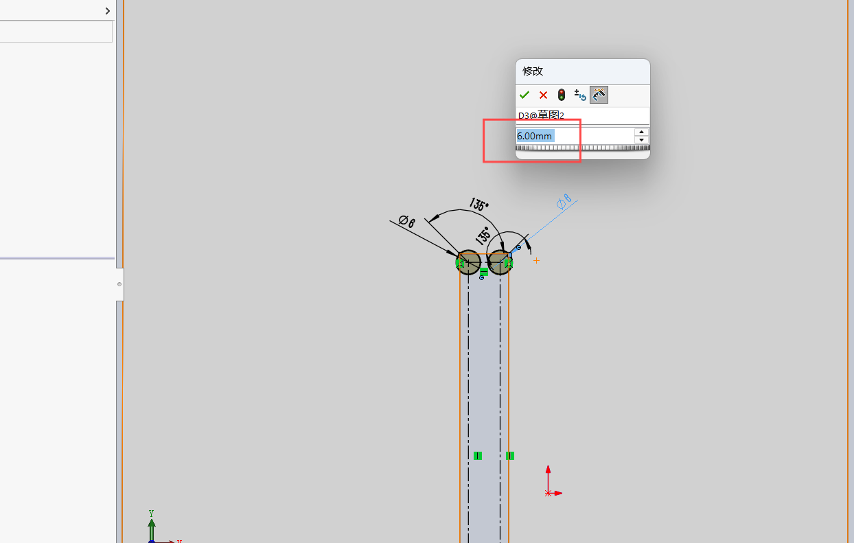
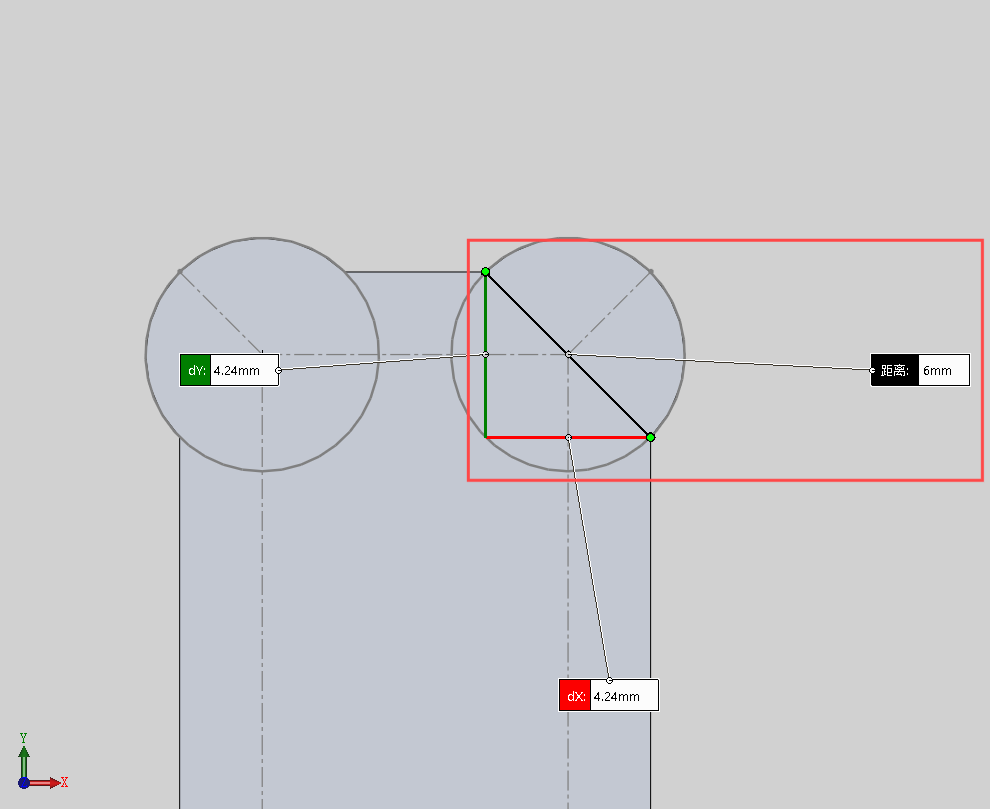
Draw 6mm circles for the dogbones and perform an extruded cut.
The distance between the entry and exit points of the toolpath is also 6mm.Therefore, a 3mm end mill is used for pocket clearing afterward.
Complete the design of the test piece.
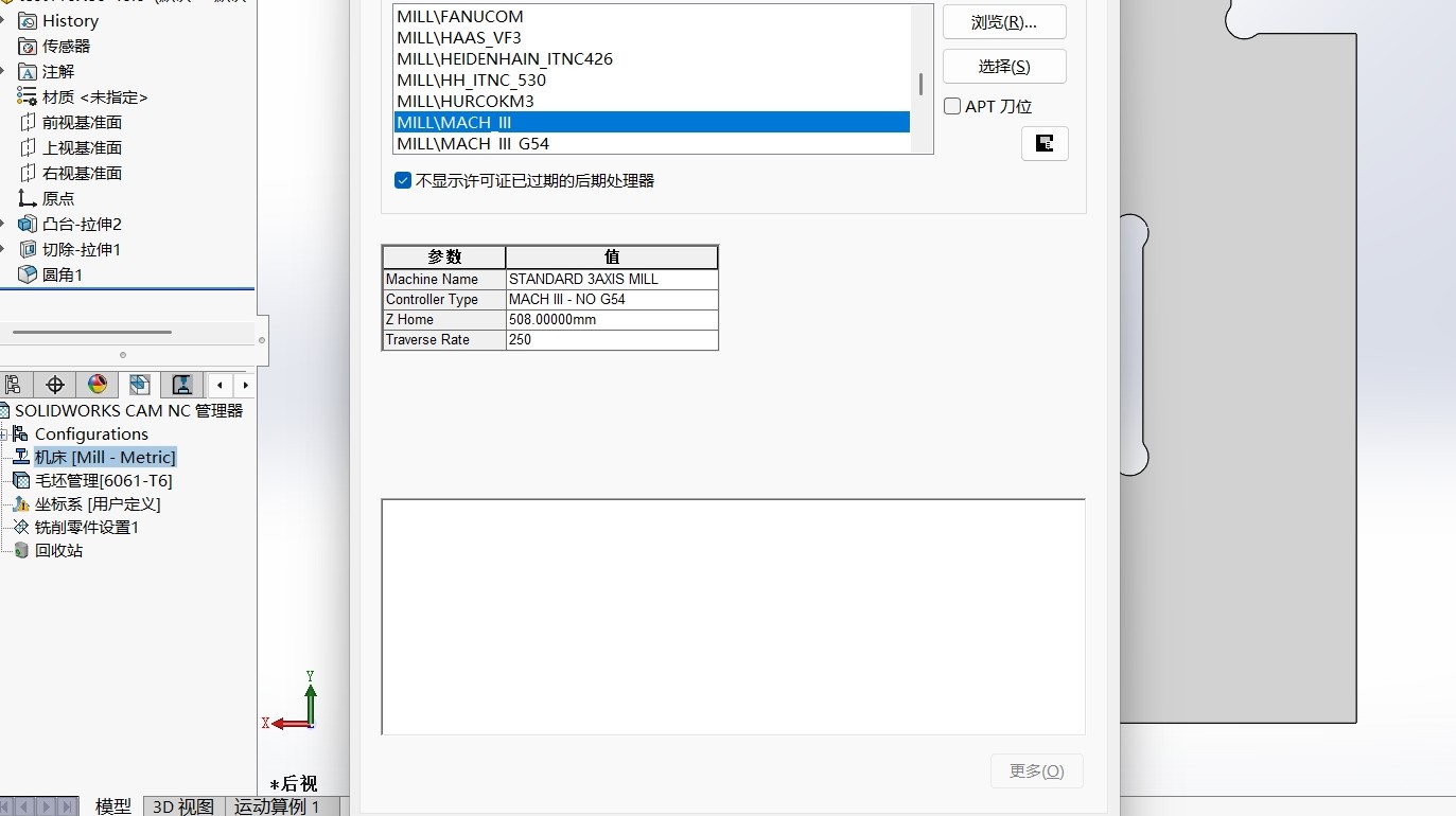
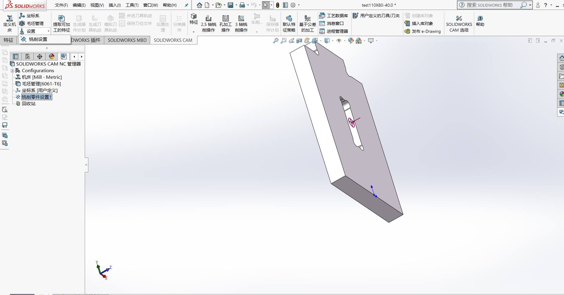
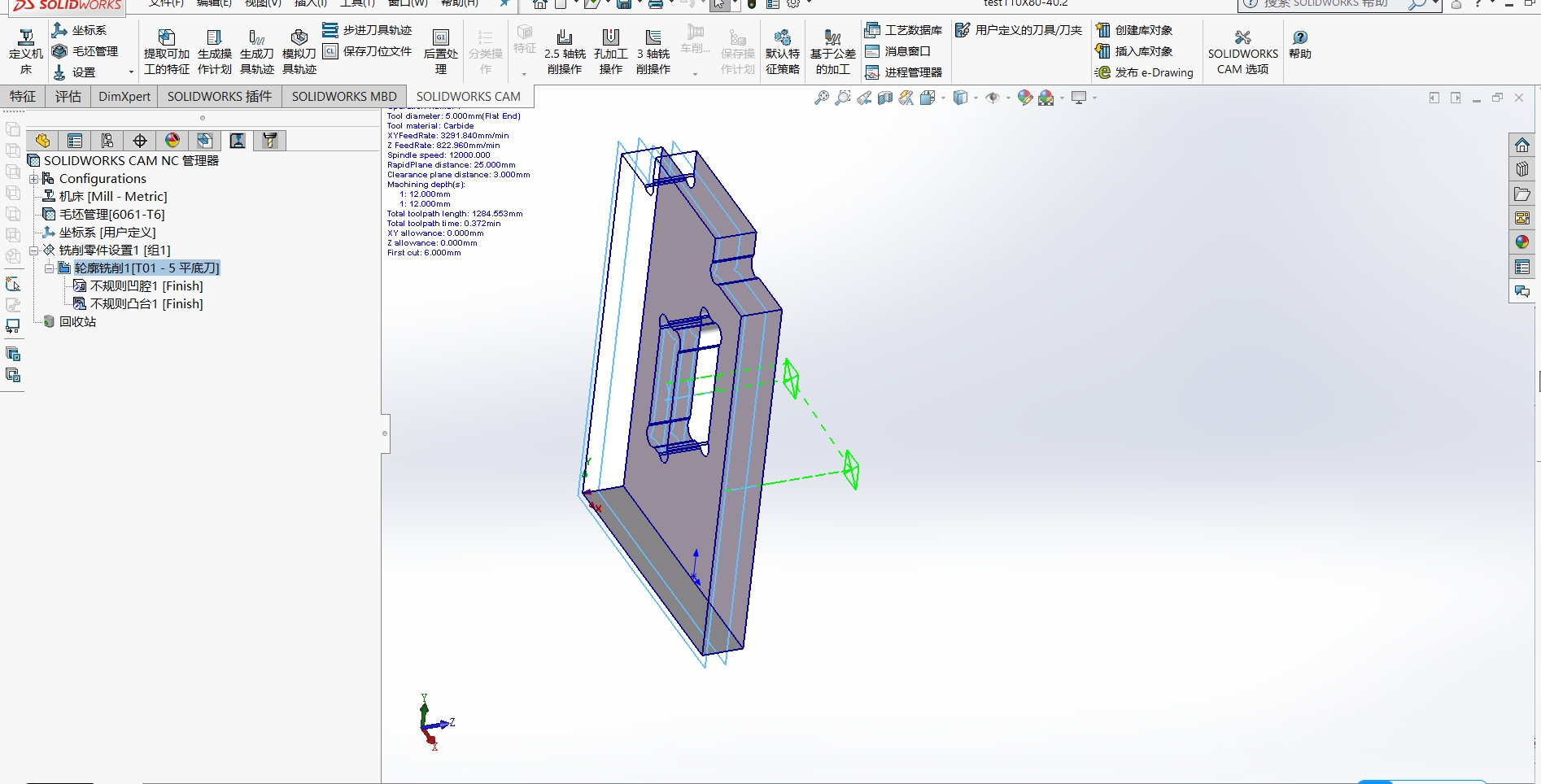
2.2 Generate the NC file.
Machine / Post-processor Post-processor: MILLMACH III (machine model) — Confirm.
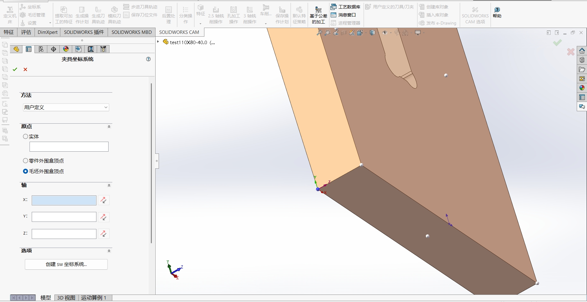
Coordinate System Check coordinate system — verify X, Y, Z axis directions are correct.
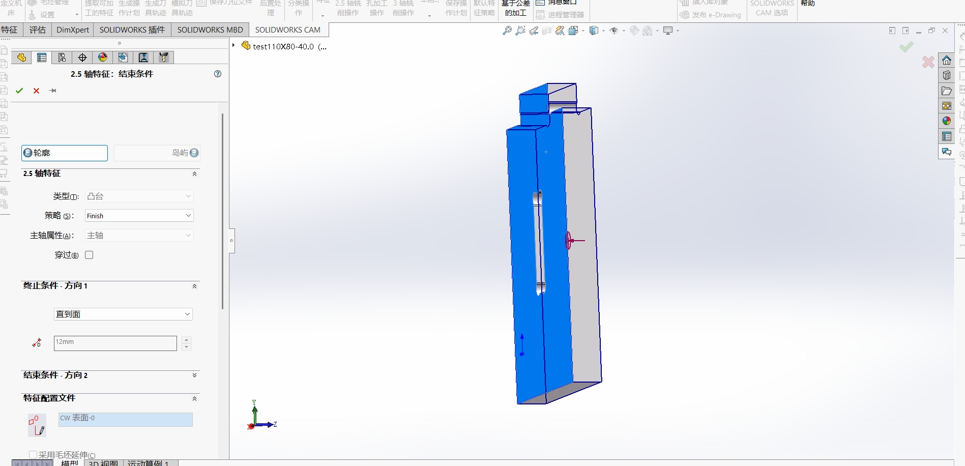
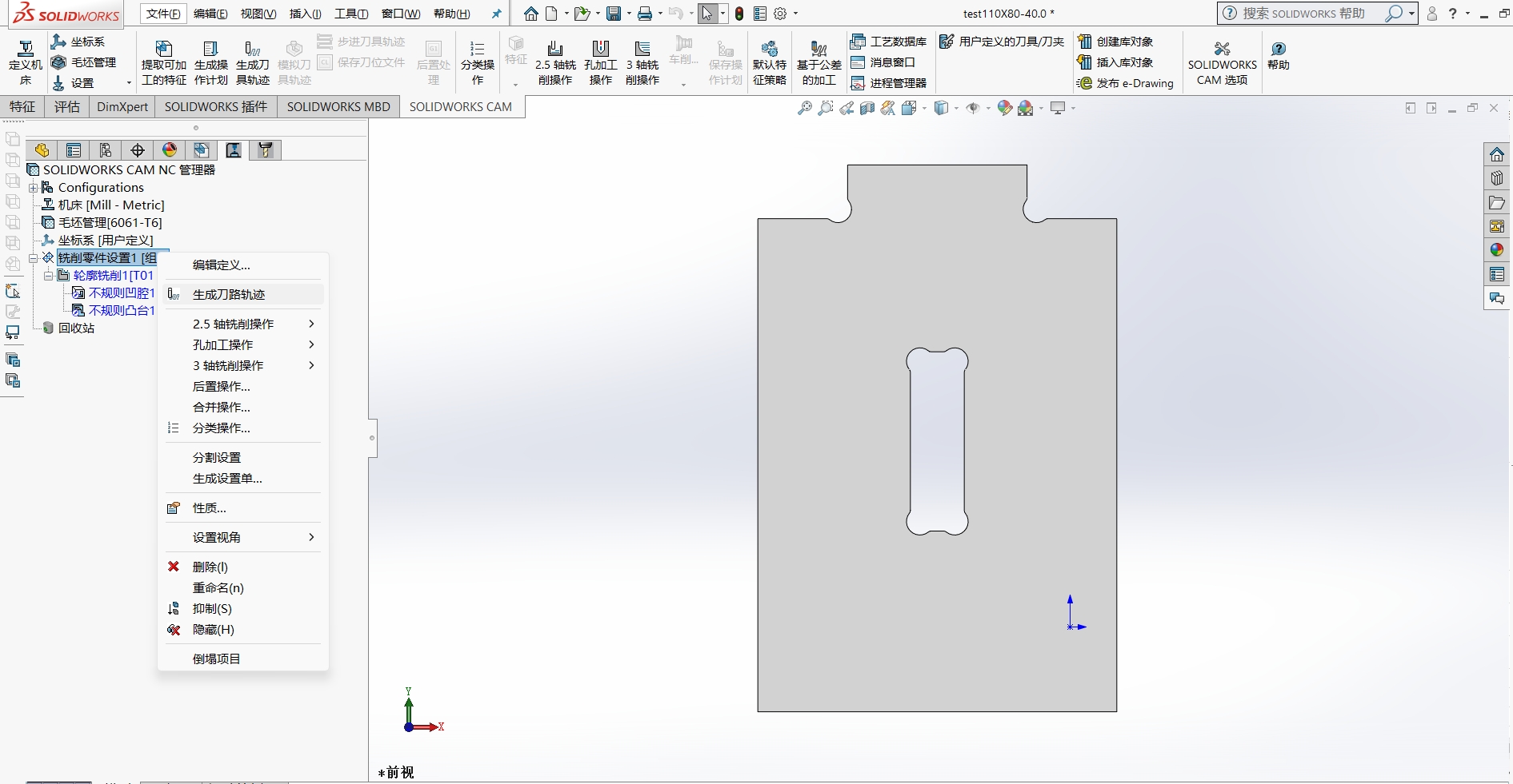
Setup → Milling → Select Tool Machining Face → 2.5-axis features
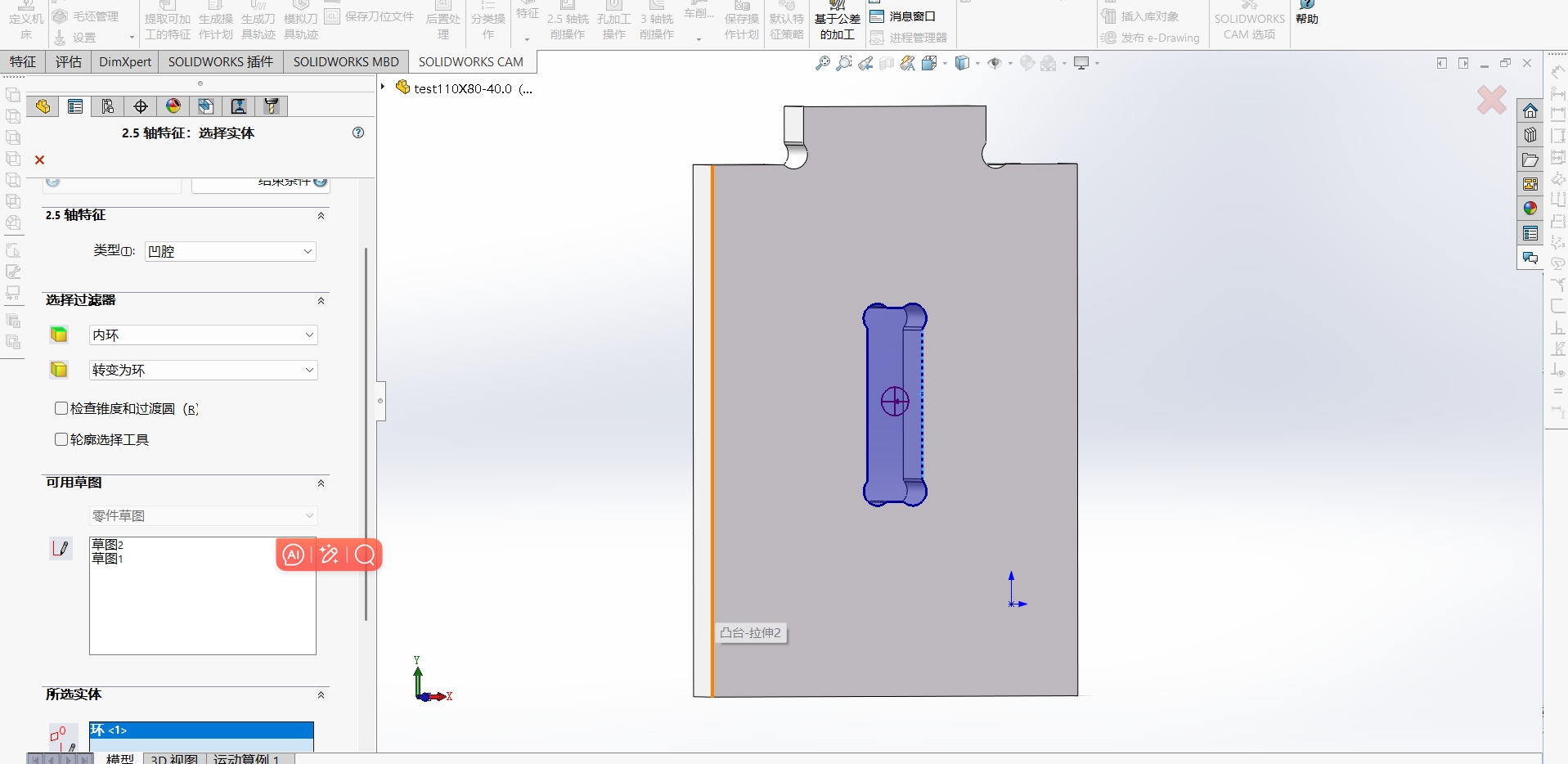
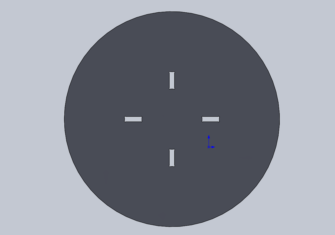
Pocket Settings
A. Pocket → Inner loop → convert to loop → selected entity (select inner loop) — inner_loop_1.
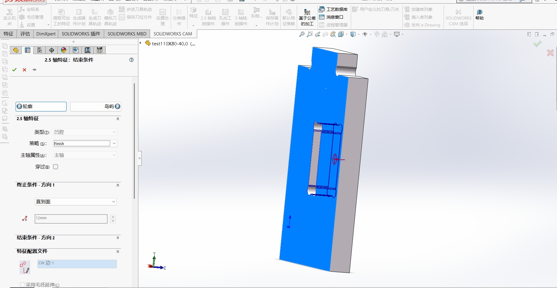
B. End condition → Strategy: Finish → Termination condition: Up to face → select back face (12 mm).
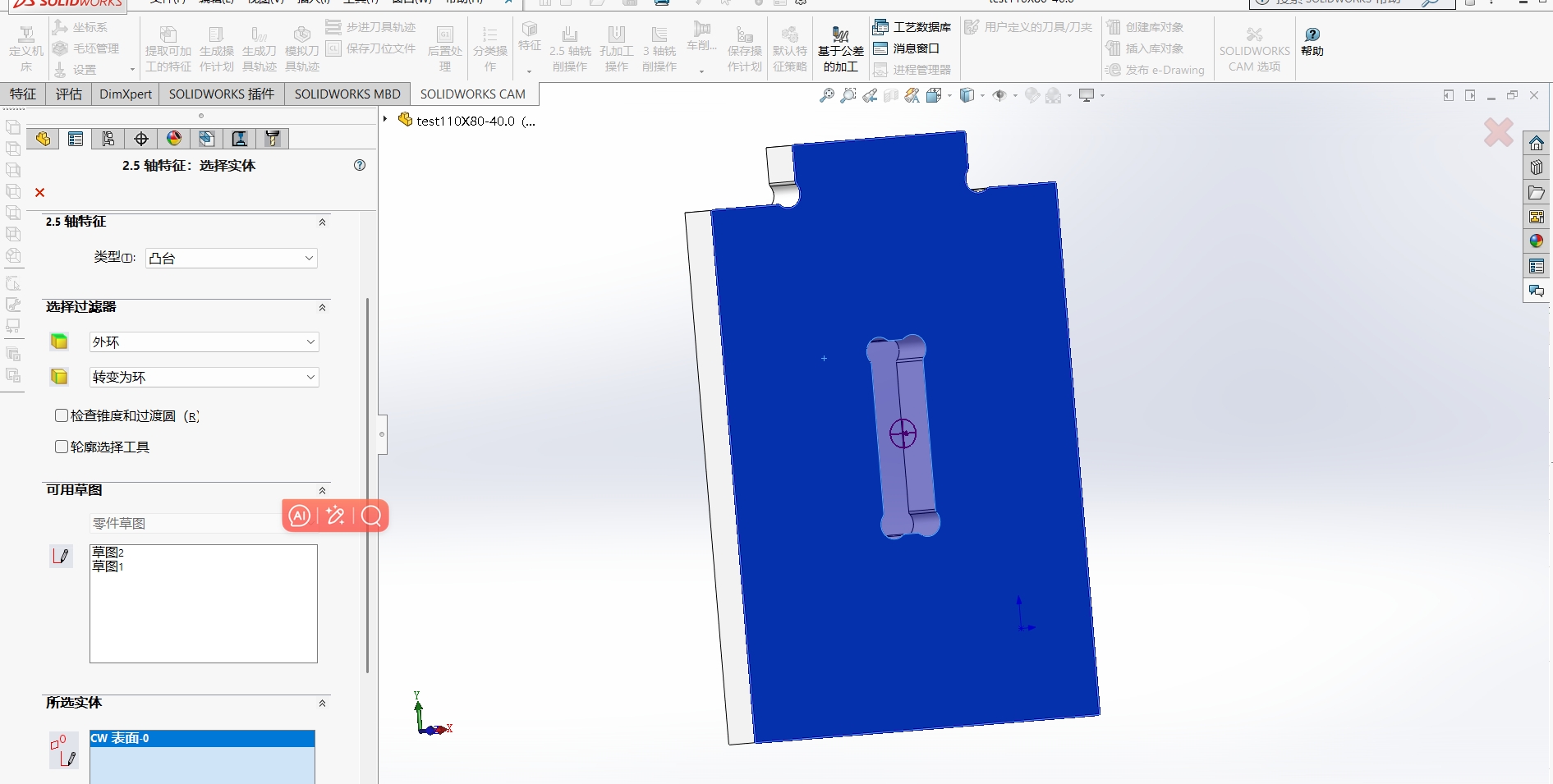
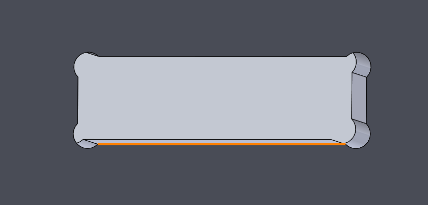
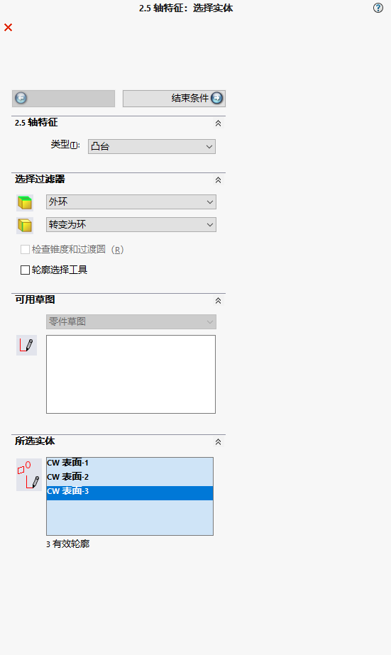
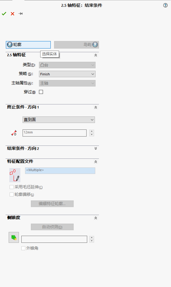
Boss (Raised area) Settings
A. Boss (island) → Outer loop → convert to loop → selected entity (select top surface) — face_1.
B. End condition → Strategy: Finish → Termination condition: Up to face → select back face (12 mm).
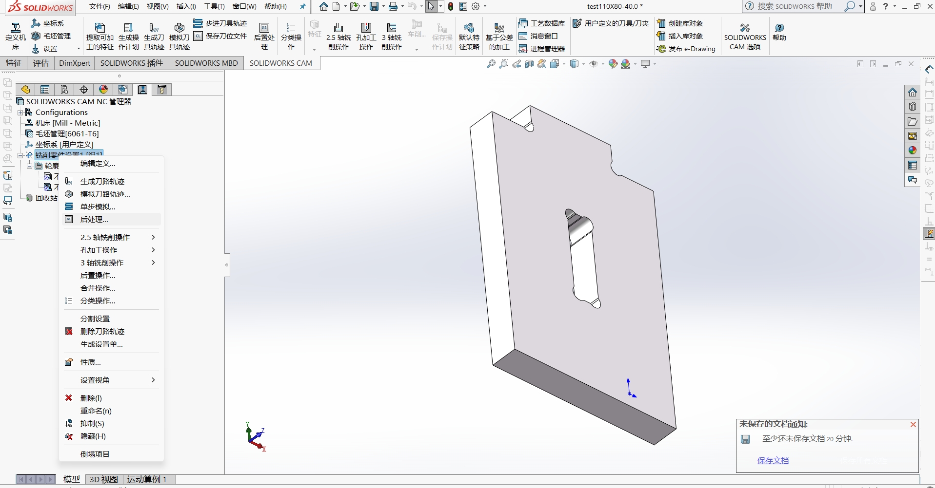
Select milling operations and choose a flat end mill.A 6mm contour cut, with a 3mm end mill used for pocket clearing.
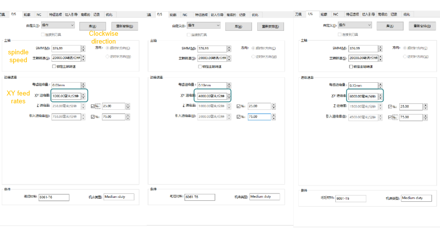
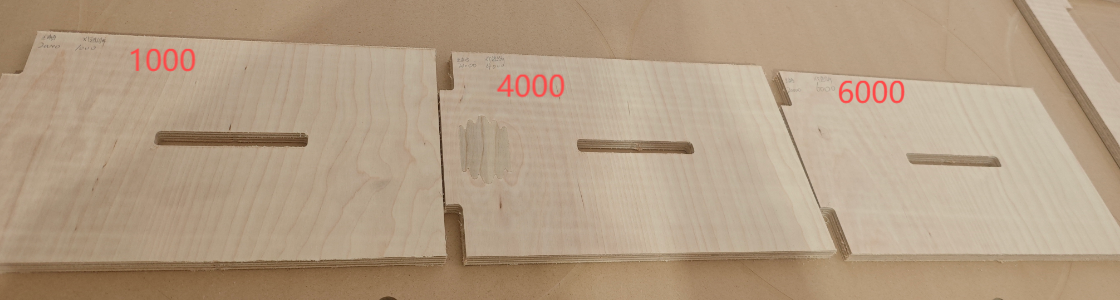
Test clockwise direction at spindle speed 20,000 rpm, XY feed rates: 1000 mm/min, 4000 mm/min, 6000 mm/min, and check cutting status and joint performance.
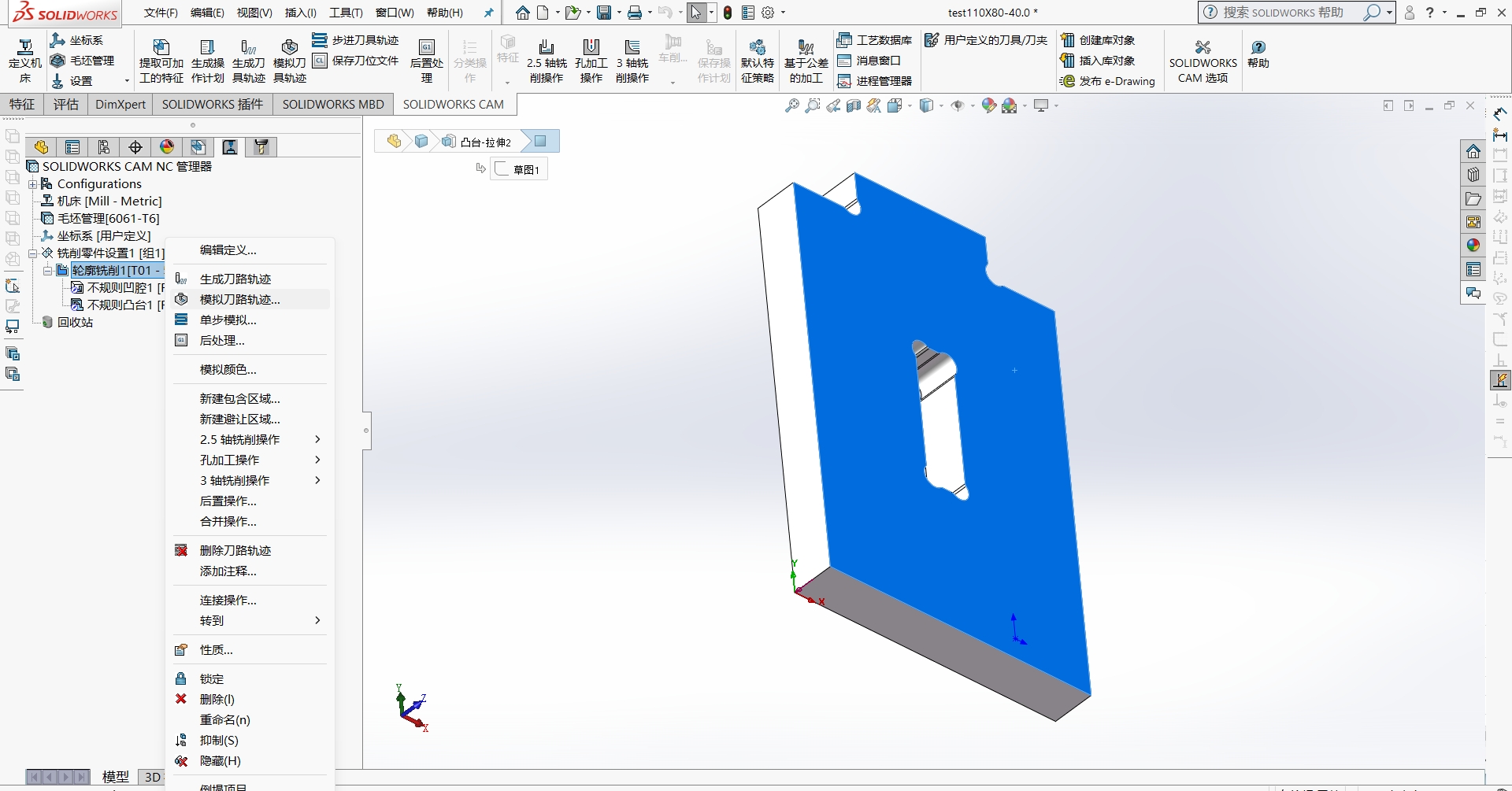
Generate toolpaths Milling part settings → Generate toolpath(s). Verify that the tool touches the correct face (confirm it is the intended top/front surface).
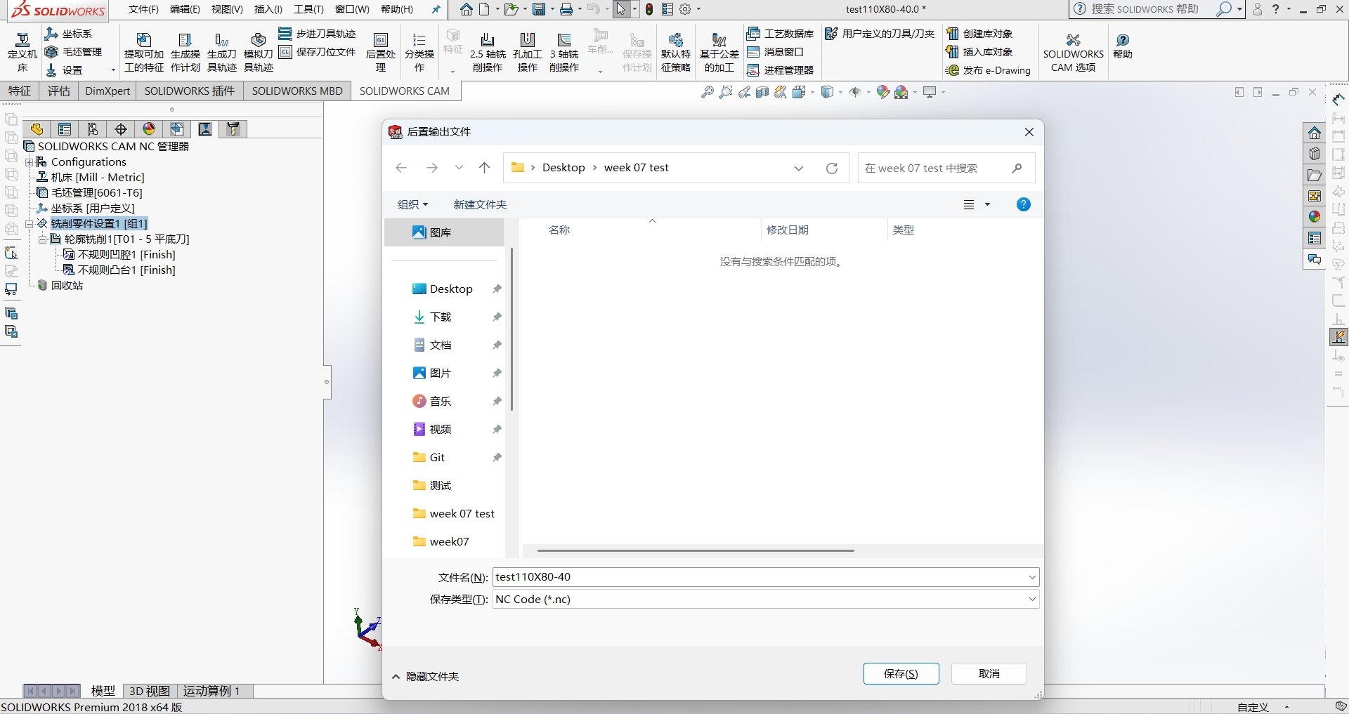
Post-processMilling part settings → Post Process → Save the output as a .NC file.
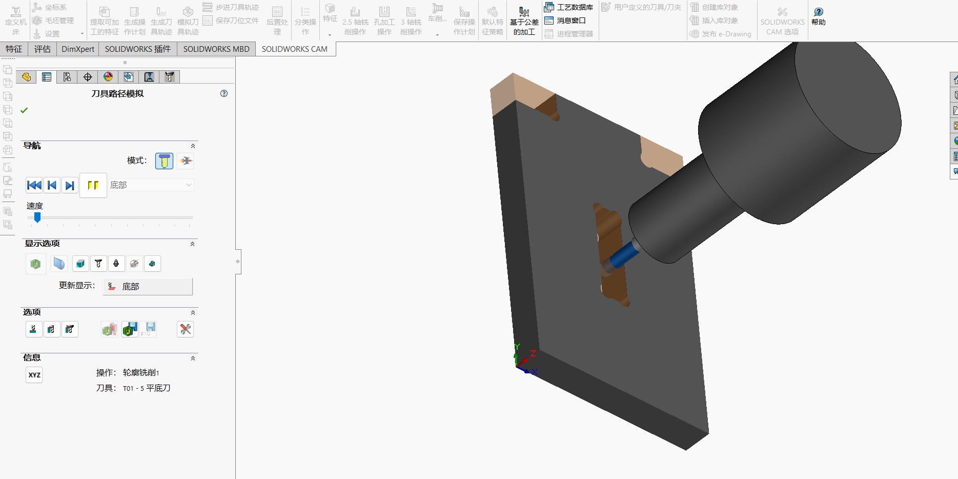
Tool Simulation.
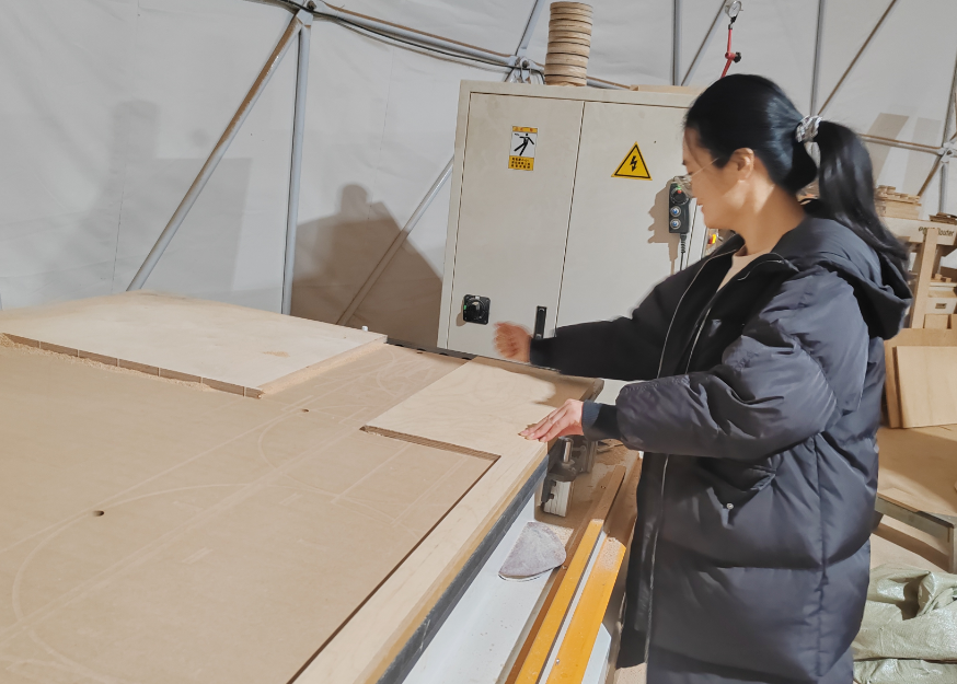
2.3 Machine the test piece
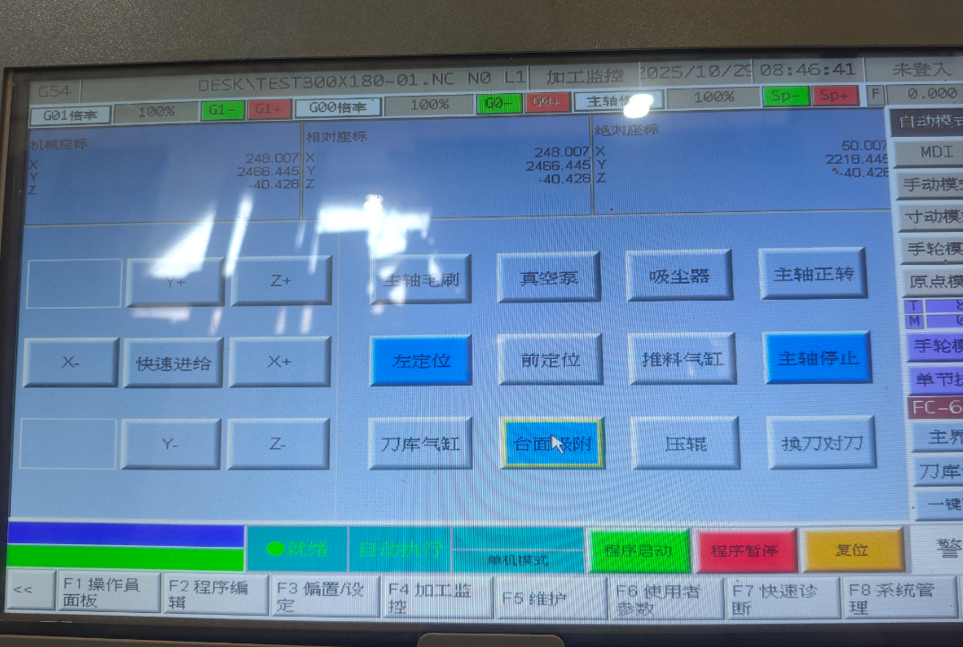
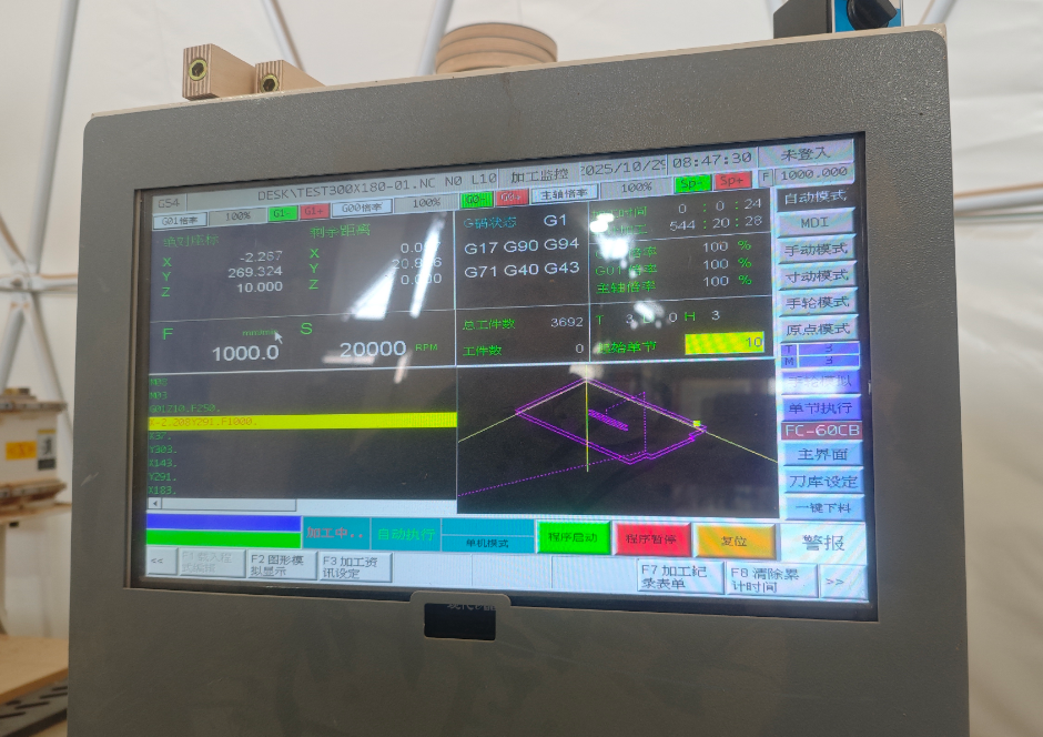
Use a USB drive to upload the NC file to the SYNTEC system,and the cutting settings are configured.
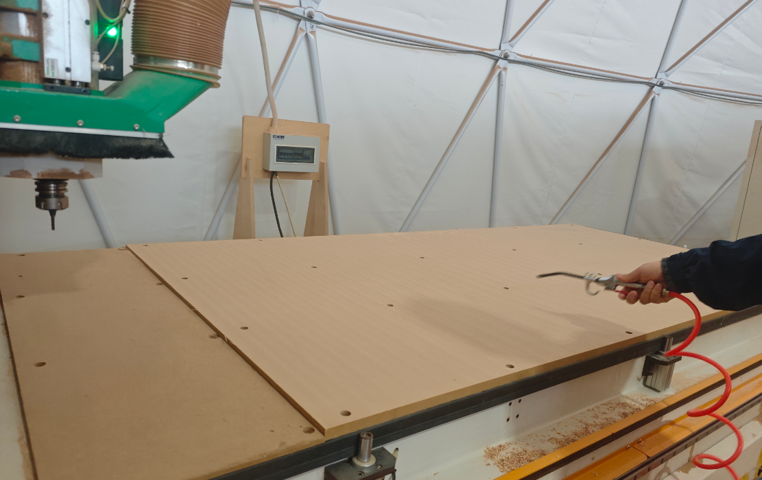
Use an air gun to clean the machine.
Automatically held by suction.
Start cutting.
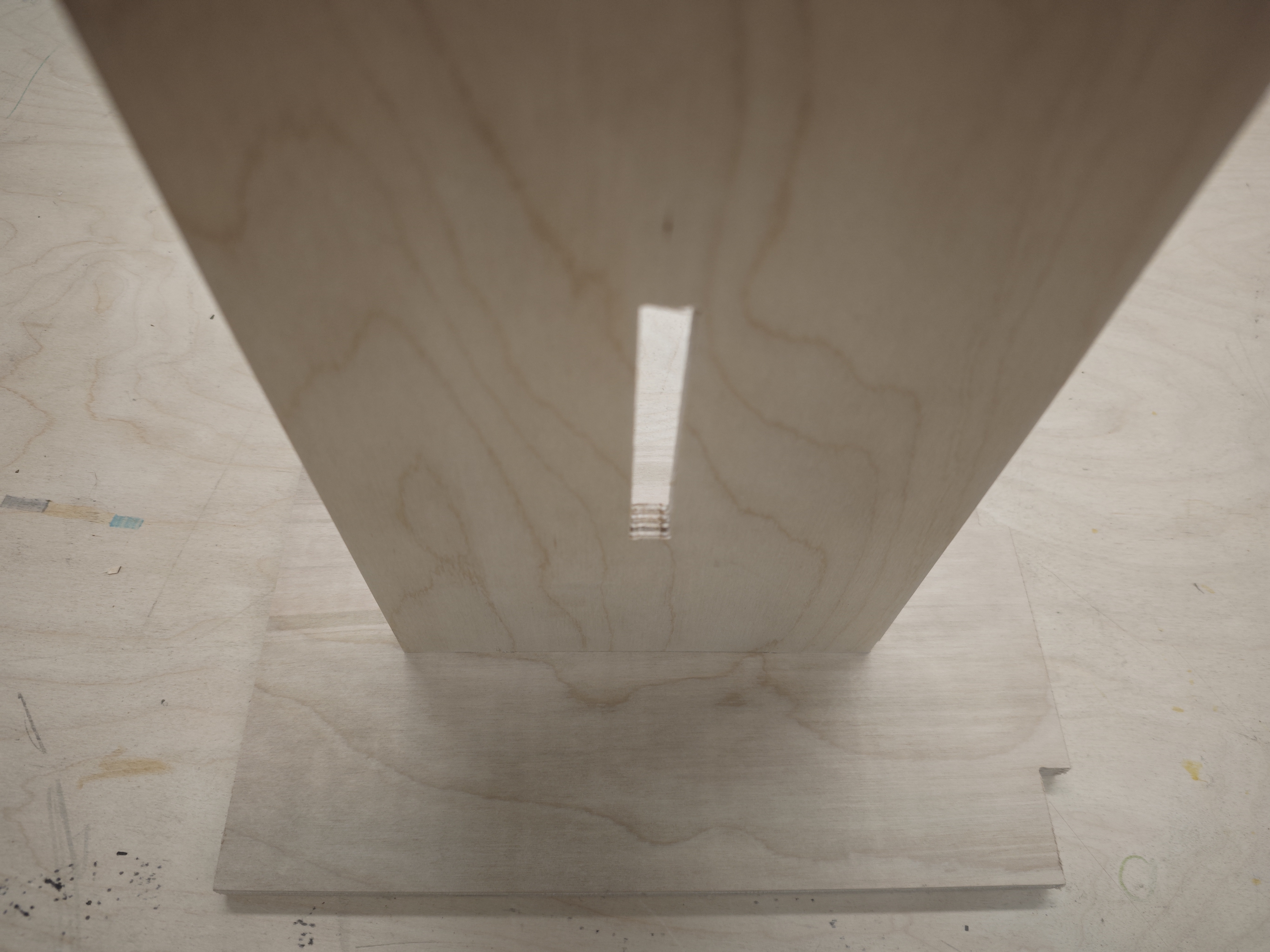
2.4 Test Results
Results: at low, medium, high feed rates, higher speeds produced smoother wood surfaces.
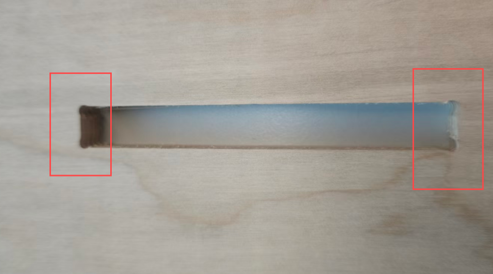
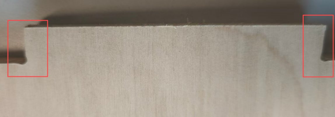
The cutting condition of the dogbone is very good.
After edge finishing, assembly test fit was good.
Individual Assignment
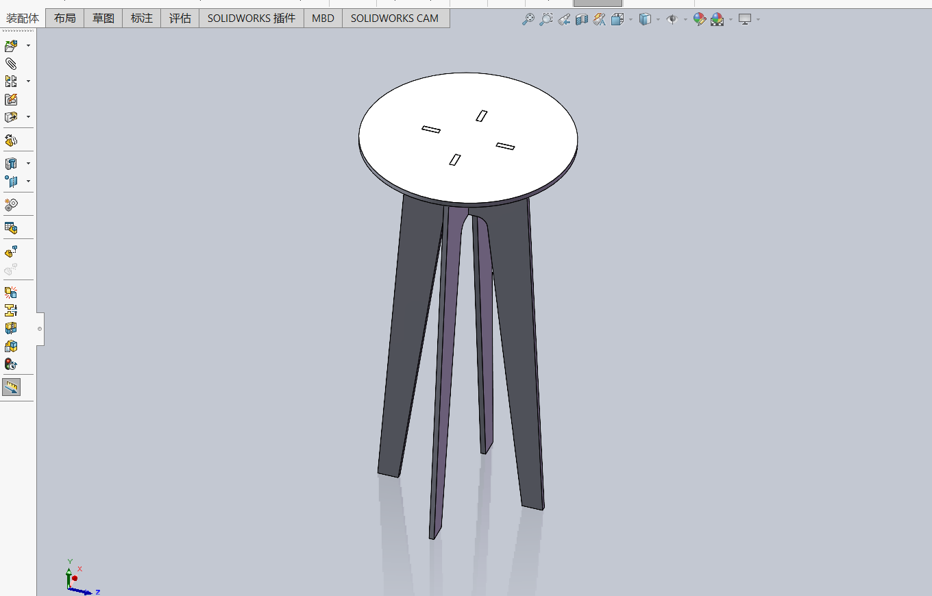
I designed a multifunctional tall stand that works both as a plant stand to bring nature indoors and as a computer desk for teaching or presentations.
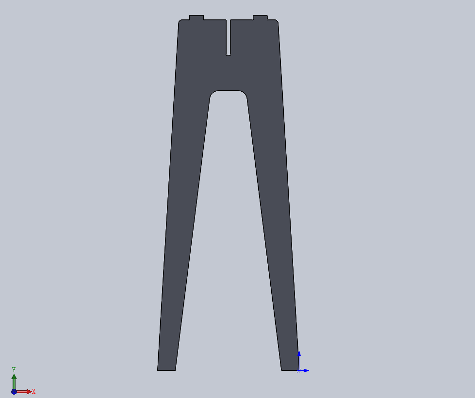
I designed the high-legged table in SolidWorks.
1.1 Design Process.
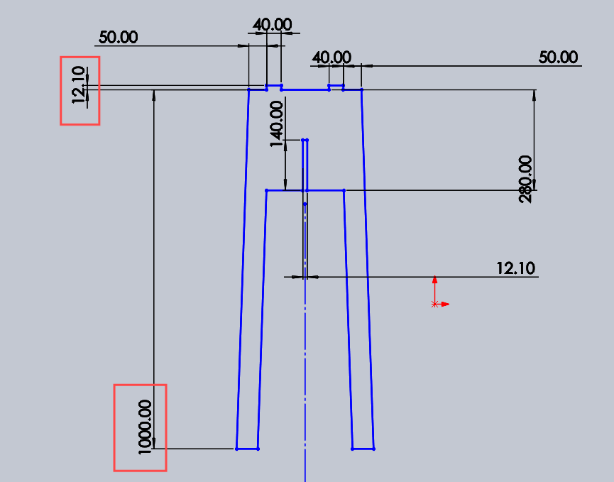
Draw a closed sketch with overall dimensions of 1000 × 500 mm, and design the slot width as 12.1 mm.
Extrude the sketch as a boss feature with a thickness of 12.1 mm (the thickness of the board).
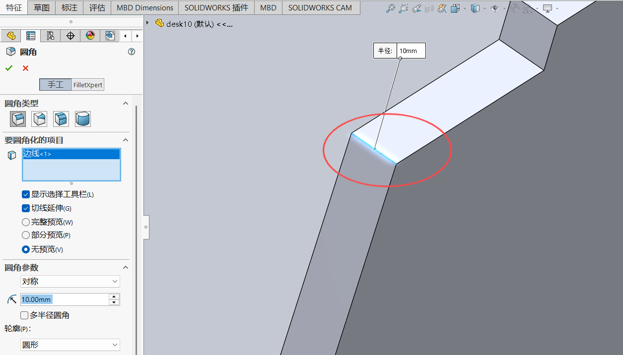
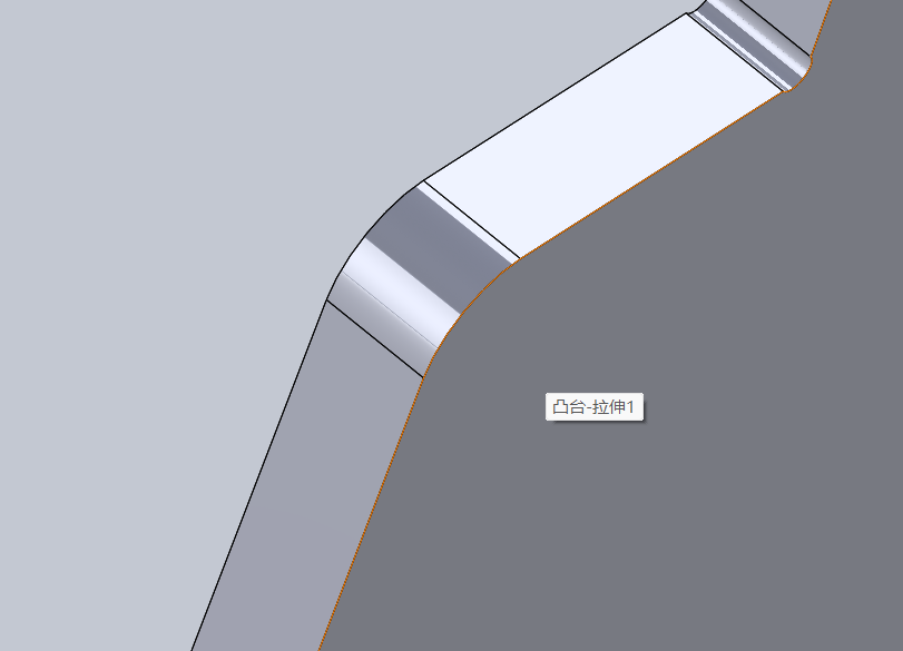
Fillet the sharp corners.
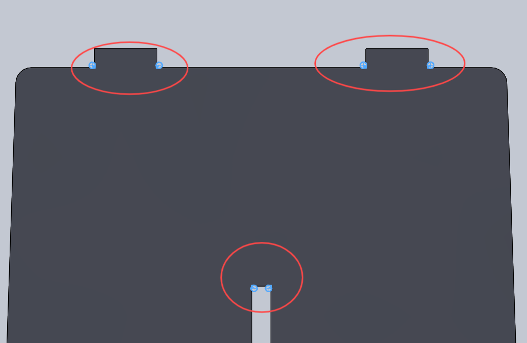
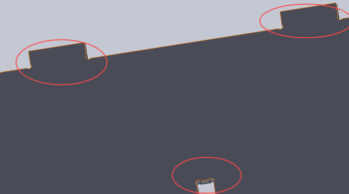
Draw a 2 mm circle to create the dogbone connection.
Use extruded cut to complete the through holes.
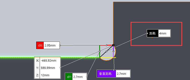
Check that the dogbone connection size is 4 mm to ensure that a 3 mm flat end mill can clear the corners.
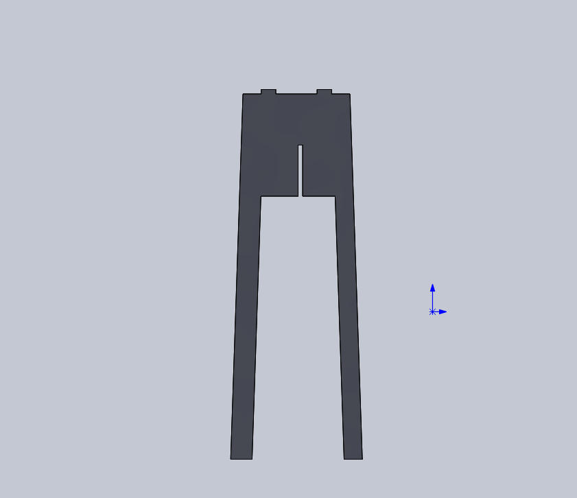
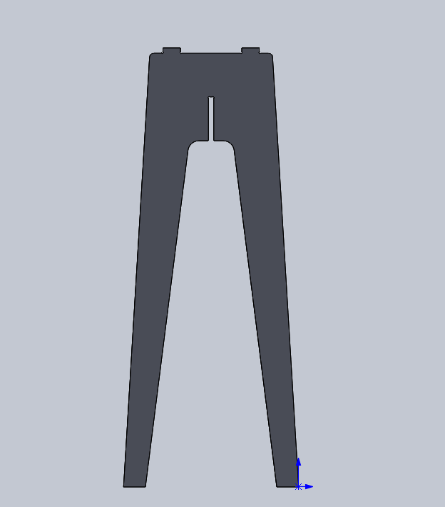
Complete the first table leg.
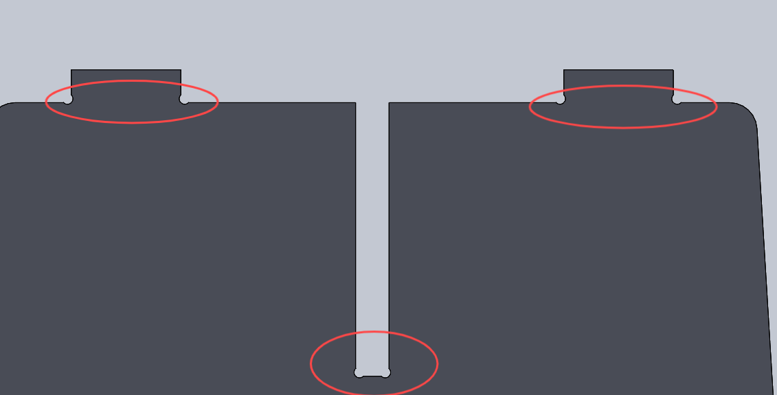
For the second table leg, adjust the slot position as shown.
Complete the second table leg.
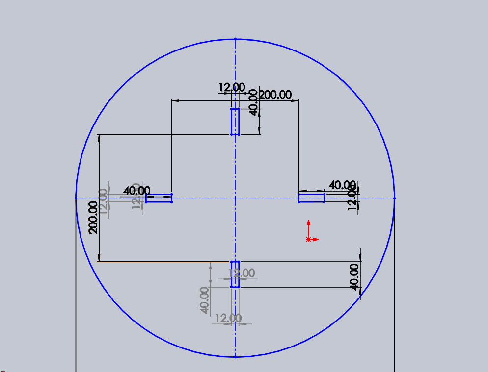
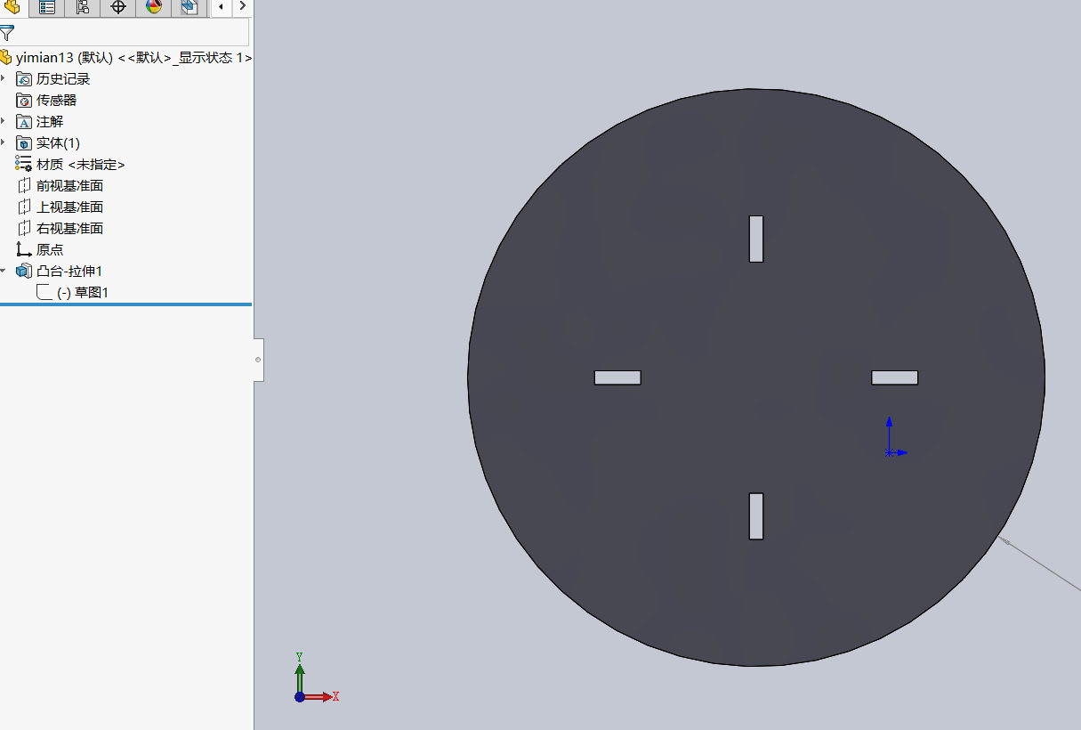
Finally, draw the tabletop sketch with a circle of 500 mm diameter.
Extrude the sketch as a boss feature with a thickness of 12.1 mm (the thickness of the board).
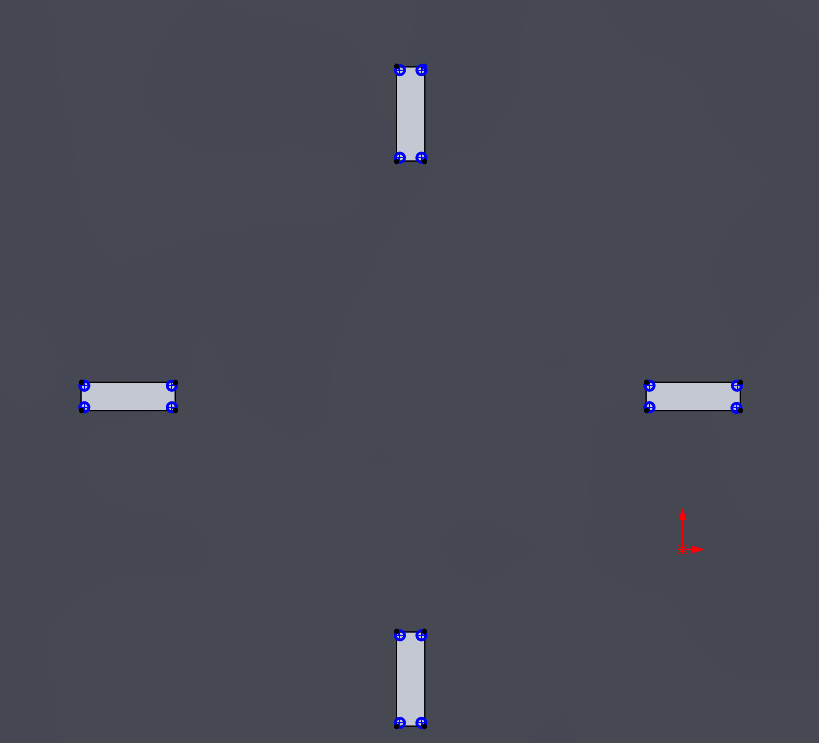
Draw a 2 mm circle to create the dogbone connection.
Use extruded cut to complete the through holes.
Complete the tabletop.
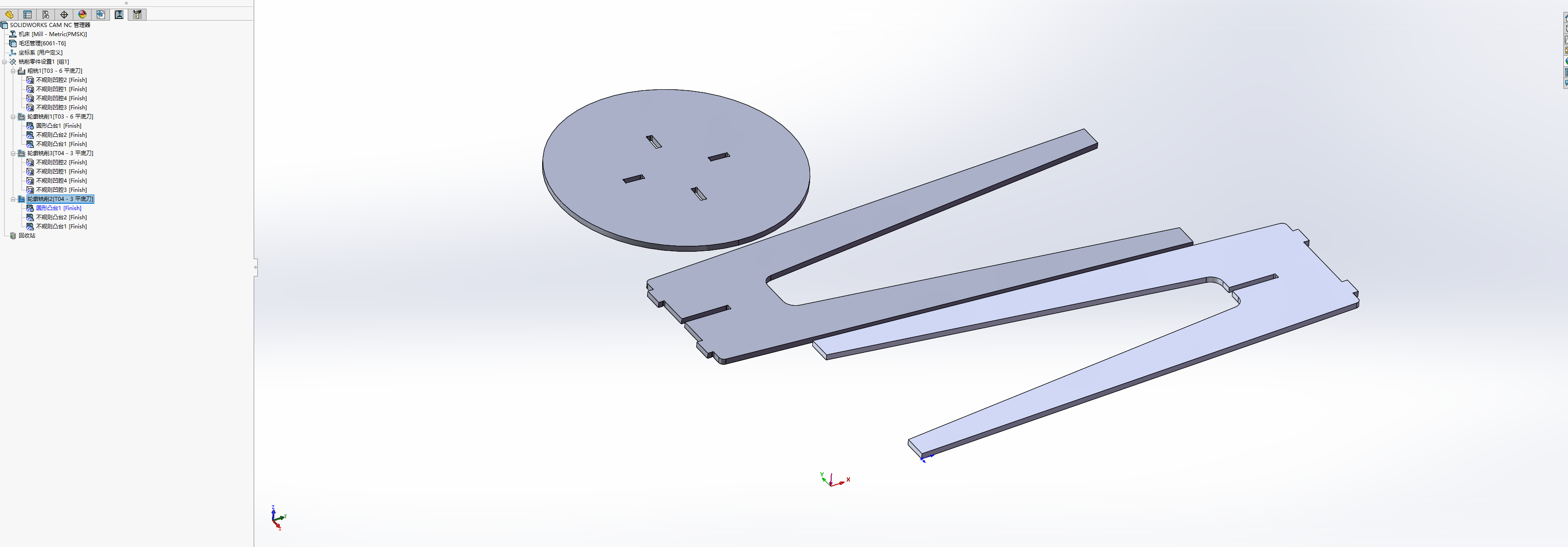
1.2 Generate NC file
Pocket Settings & Boss (Raised area) Settings
Setup finished
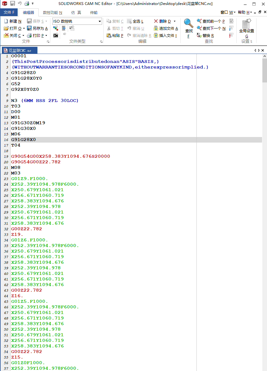
NC file
1.3 Processing and Fabrication
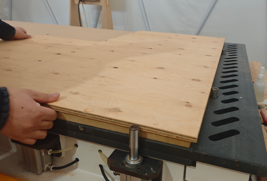
Automatically held by suction
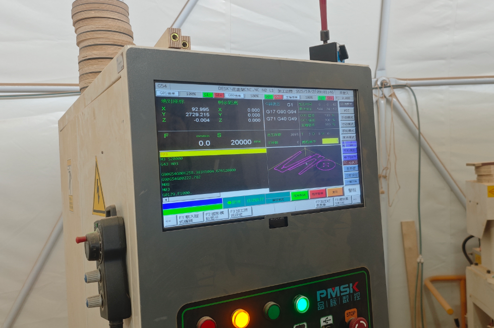
The NC file is uploaded to the SYNTEC system via a USB drive, and the cutting settings are configured.
Use an air gun to clean the machine.
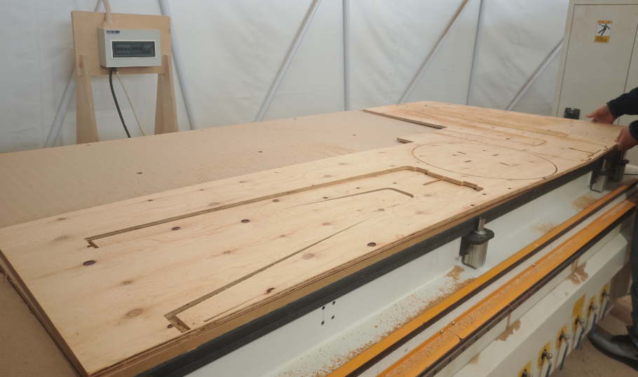
Start cutting.
After milling, we used a vacuum to clean remaining waste.To save material, we used a leftover wood board. One table leg was not fully cut.
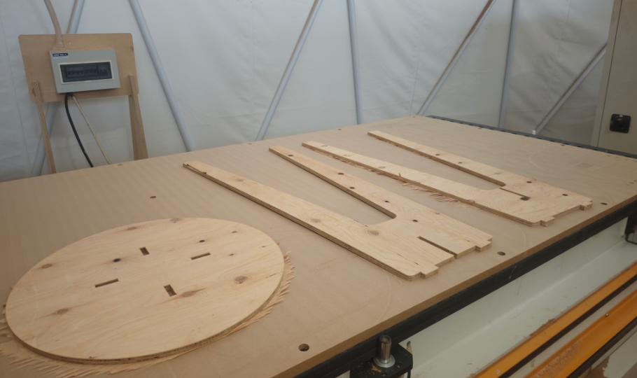
We re-positioned the board and milled again, completing the table leg.
Finished
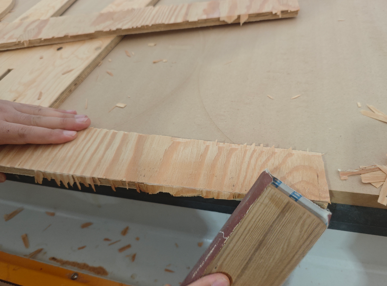
Sand the wooden board.
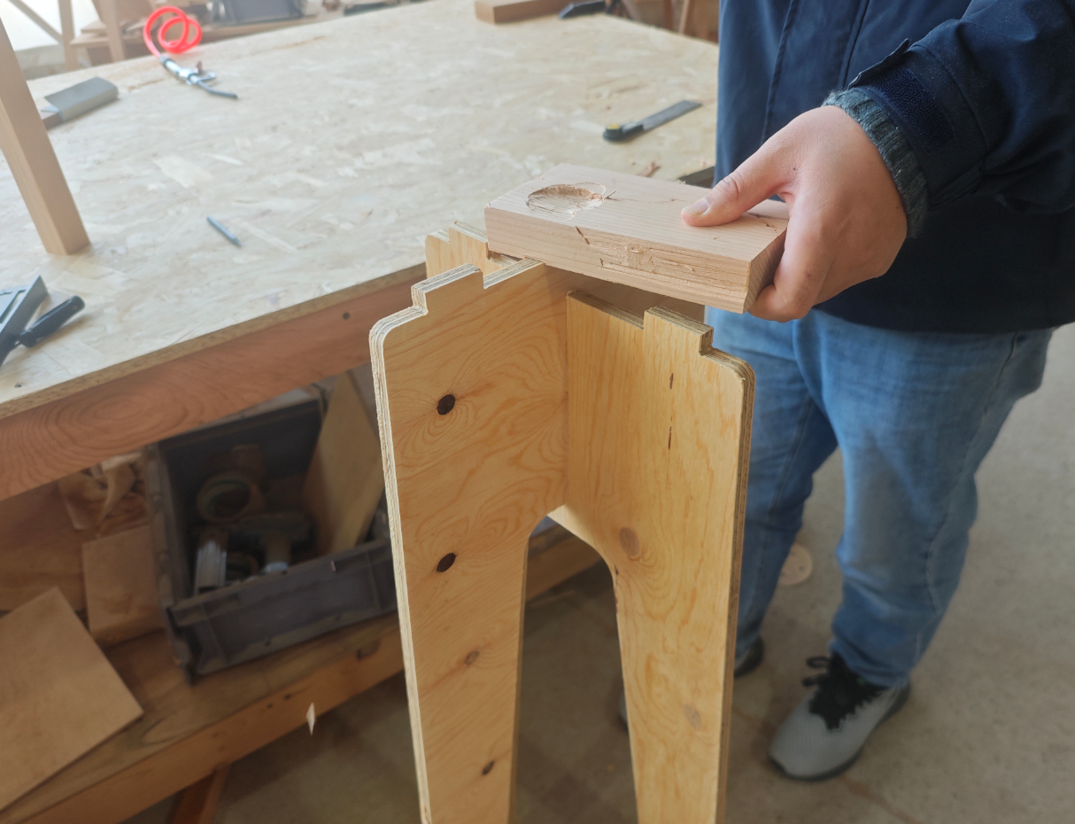
1.4 Assembling the parts was still a bit tight
First, install the table legs.
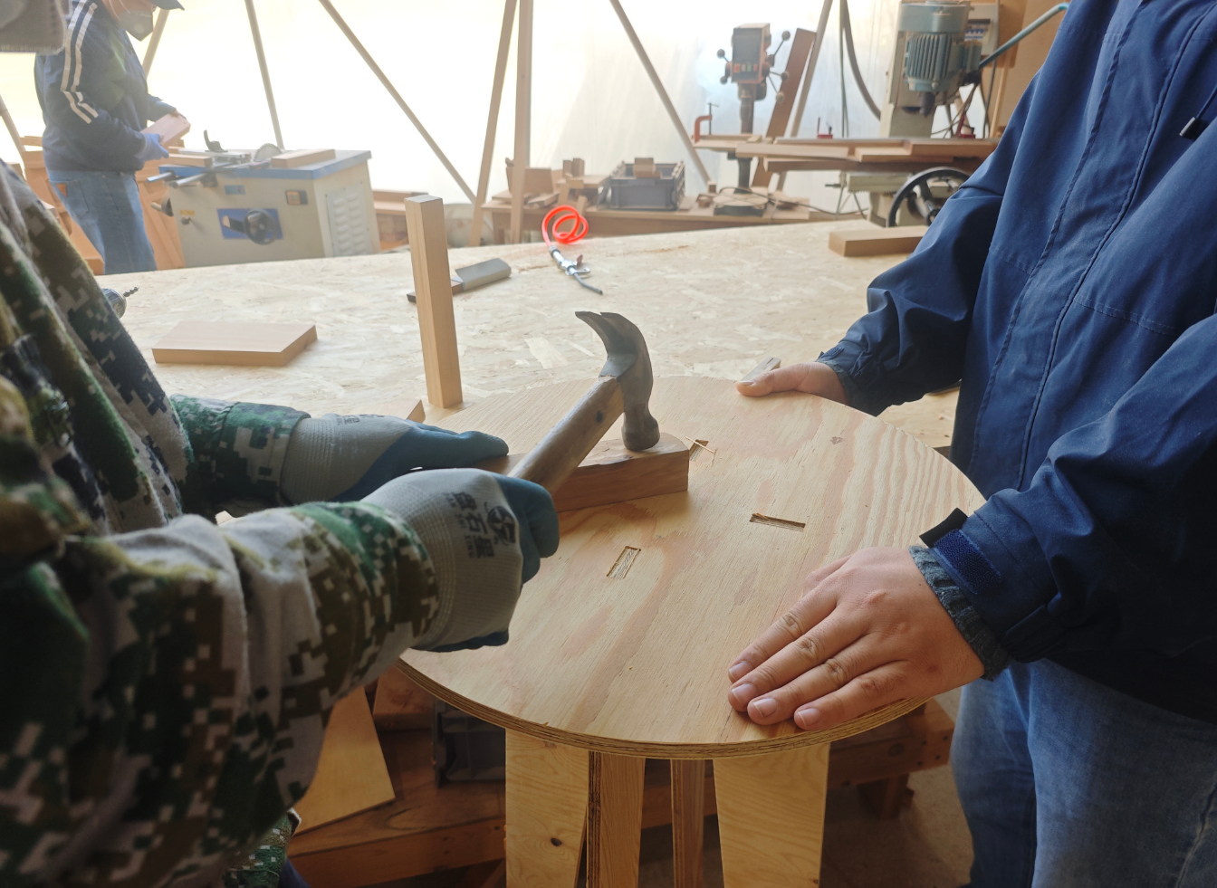
Next, install the tabletop.
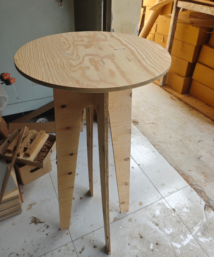
Finally, assembly was completed, producing my multifunctional high-legged table.