
Final Project:
Slide
Video
What does it do?
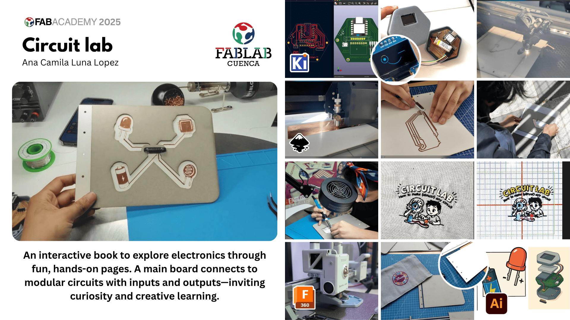
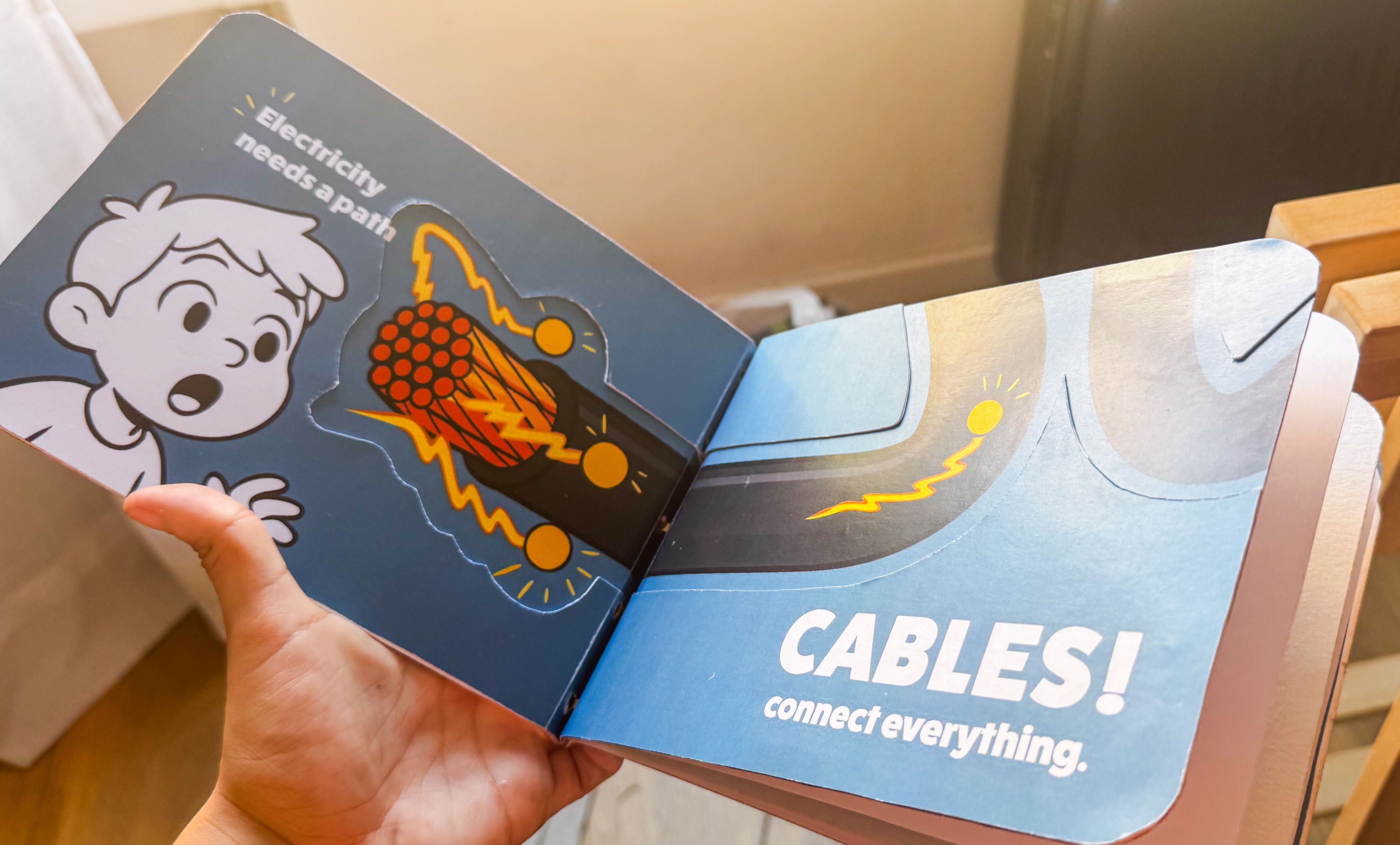
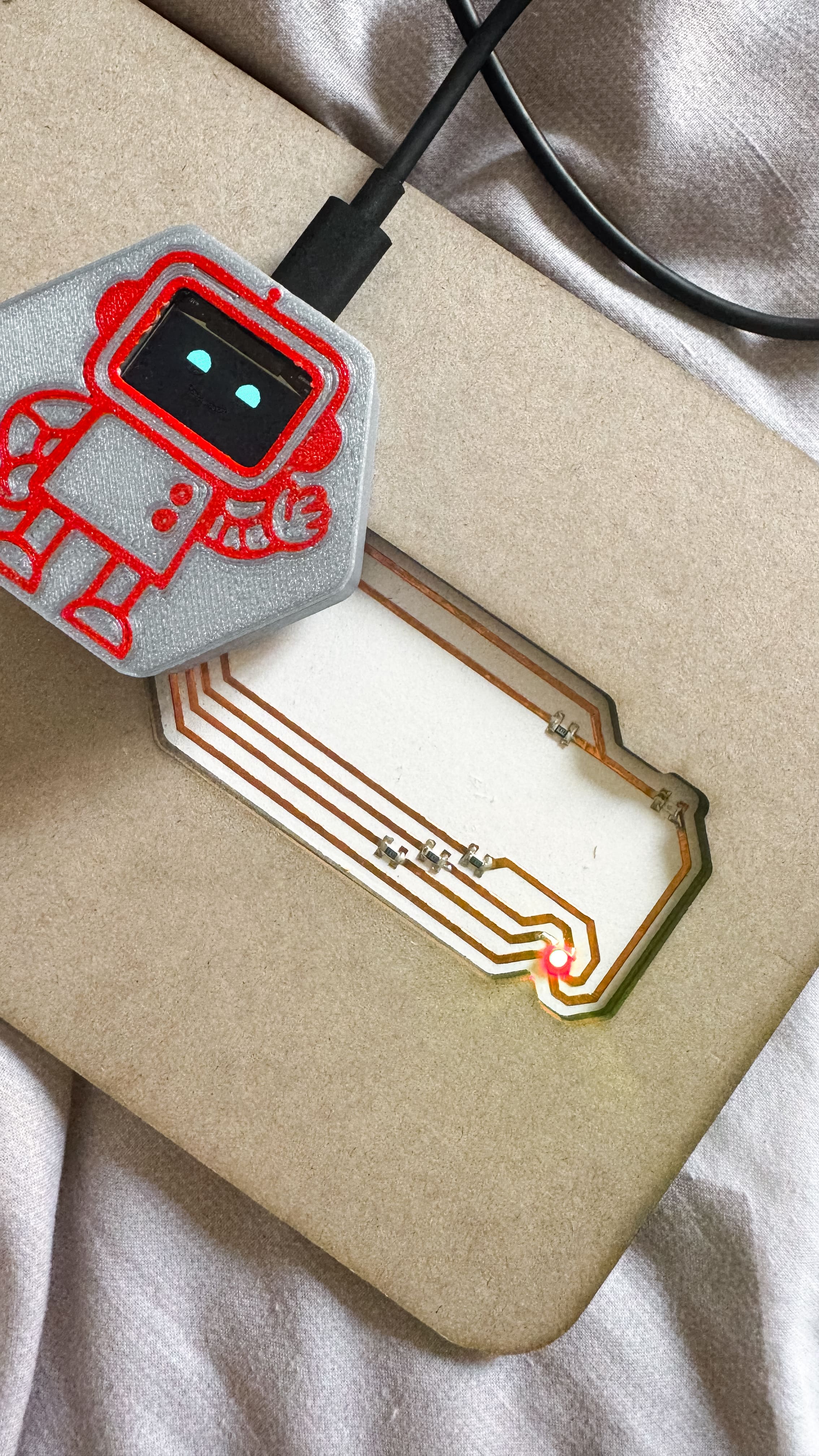
The project is an educational interactive book designed for elementary school students. It teaches basic concepts of electronics through modular pages that connect to a main board. Each interactive page contains components like input and outputs. The board reads inputs (like light or touch) and controls outputs (like RGB LEDs) to create playful, hands-on learning experiences.
Who's done what beforehand?
This project draws inspiration from a range of educational tools that merge storytelling, interaction, and electronics to teach foundational concepts in a playful way.
- Manuel Corrales’ BugBot – Teaching habitats and environmental concepts using robots and interactive boards.
- Edu Cartagena’s JEDPRO Toy – A tangible programming toy for children to learn programming concepts like sequences and loops.
- Bobby McCarthy’s Modular Blocks – Modular, programmable blocks with magnetic connectors for interaction.
- Ieva Dautartaite’s Sensation Map (2023) – explored storytelling and interaction with materials, explored interactive textile maps using embroidery, capacitive sensors, and light to represent emotional memory and body sensation.
- Astrid’s Craft Book (2012) – a digital craft book that integrated paper circuits, sewing, and narrative storytelling to create interactive pages.
More inspirations:
- Chibitronics Love to Code – Circuit stickers & storytelling for coding.
- Papier Machine – Paper circuits for interactive learning.
- Bare Conductive's Electric Paint Kit – Conductive ink for DIY electronics.
- Computer Engineering for Babies – Book-based logic learning.
What sources did you use?
This project was built using a combination of technical documentation, digital fabrication manuals, and creative references. These are the main sources consulted:
- KiCad Documentation – I used the official KiCad manual to design and route my custom PCB. This helped me understand how to define the board outline, manage net connections, and export Gerber files.
- Seeed Studio XIAO ESP32S3 Wiki – For pin mapping, technical specs, and programming reference.
🔗 XIAO ESP32S3 Official Docs - SSD1306 OLED Display Docs – I referred to resources explaining how to drive the SSD1306-based 0.96" OLED screens via I2C.
🔗 Adafruit SSD1306 Guide - MPU-6050 (GY-521) Datasheet – To understand I2C address, initialization and sensor axes.
🔗 MPU-6050 Datasheet - Ink/Stitch Documentation – To develop embroidery files (.JEF) and understand stitch types and machine compatibility.
🔗 Ink/Stitch Docs - Janome MB7 Instruction Manual – For threading, needle assignment and setup of the embroidery machine. Helped avoid trial-and-error and clarified the hardware interface.
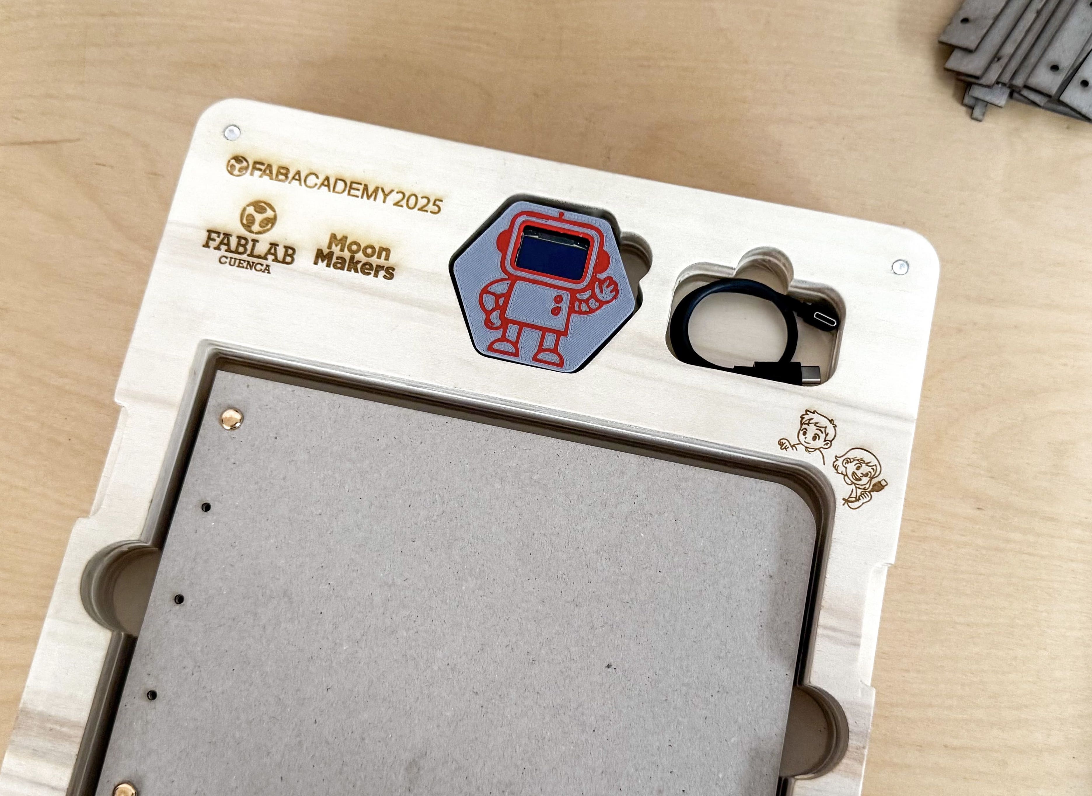
What did you design?
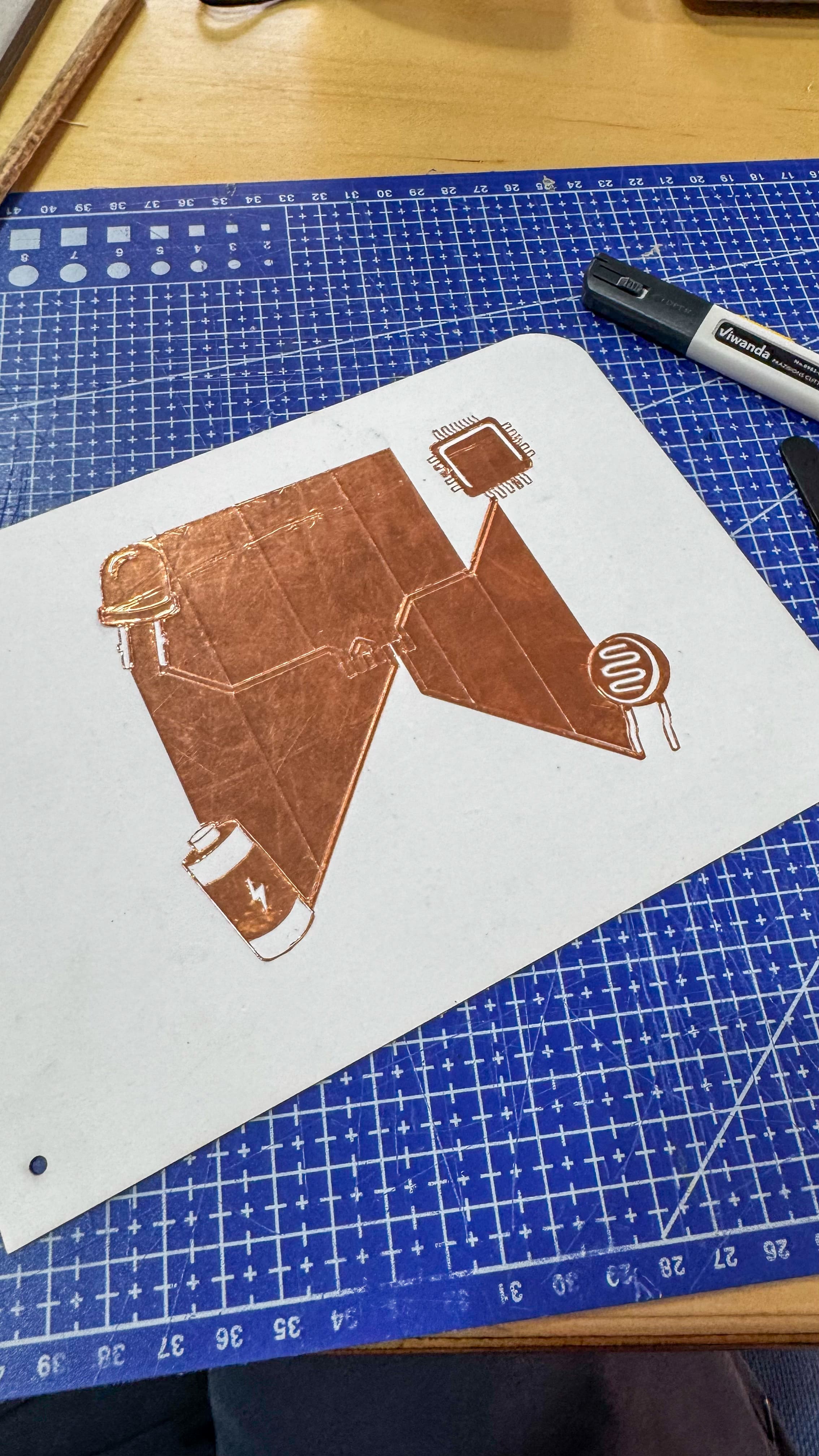
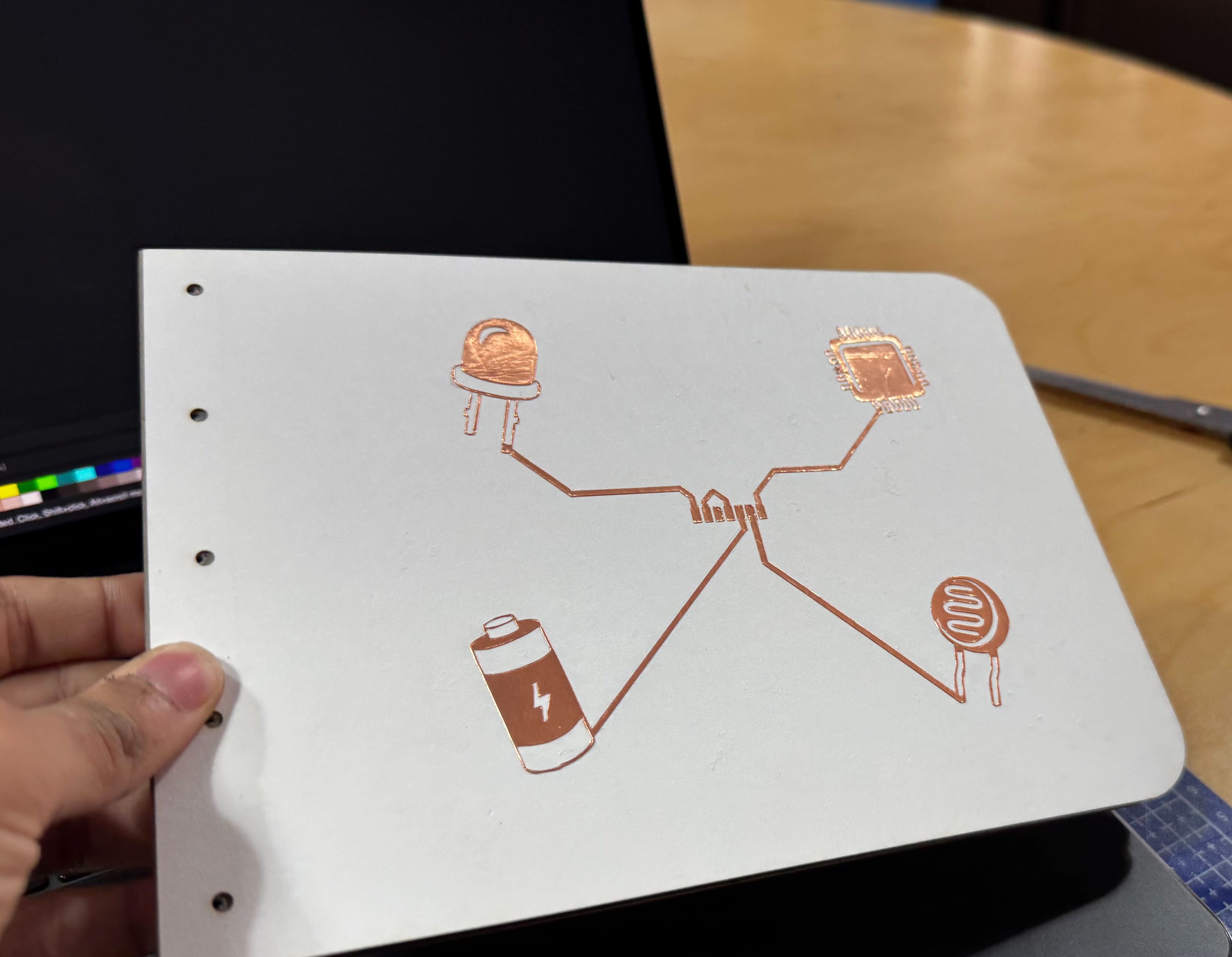
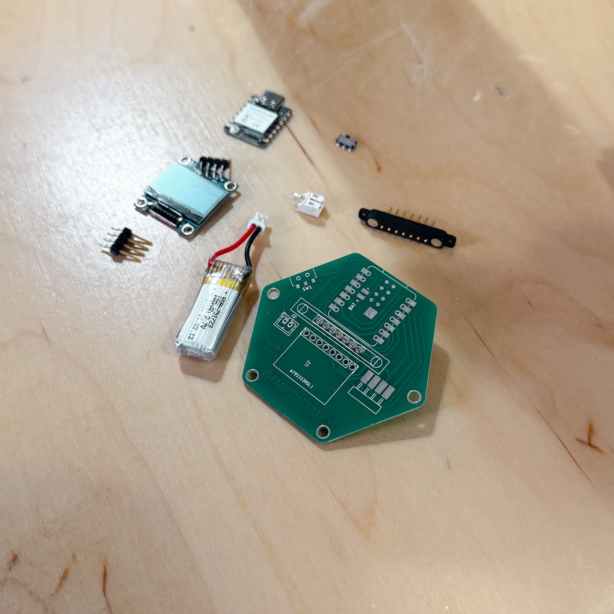
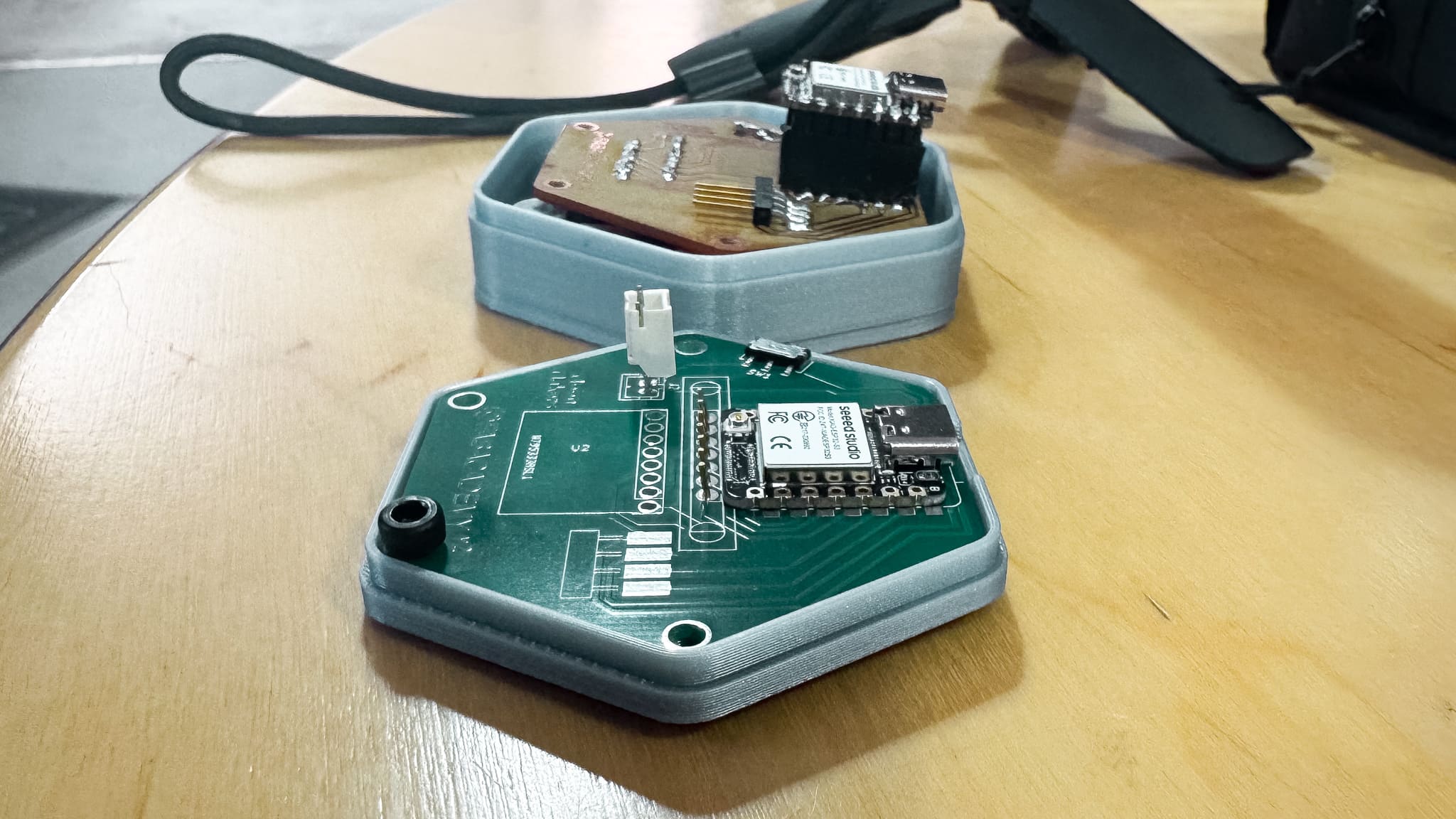
- A custom main board with Seeed XIAO ESP32-S3, OLED screen, and MPU-6050
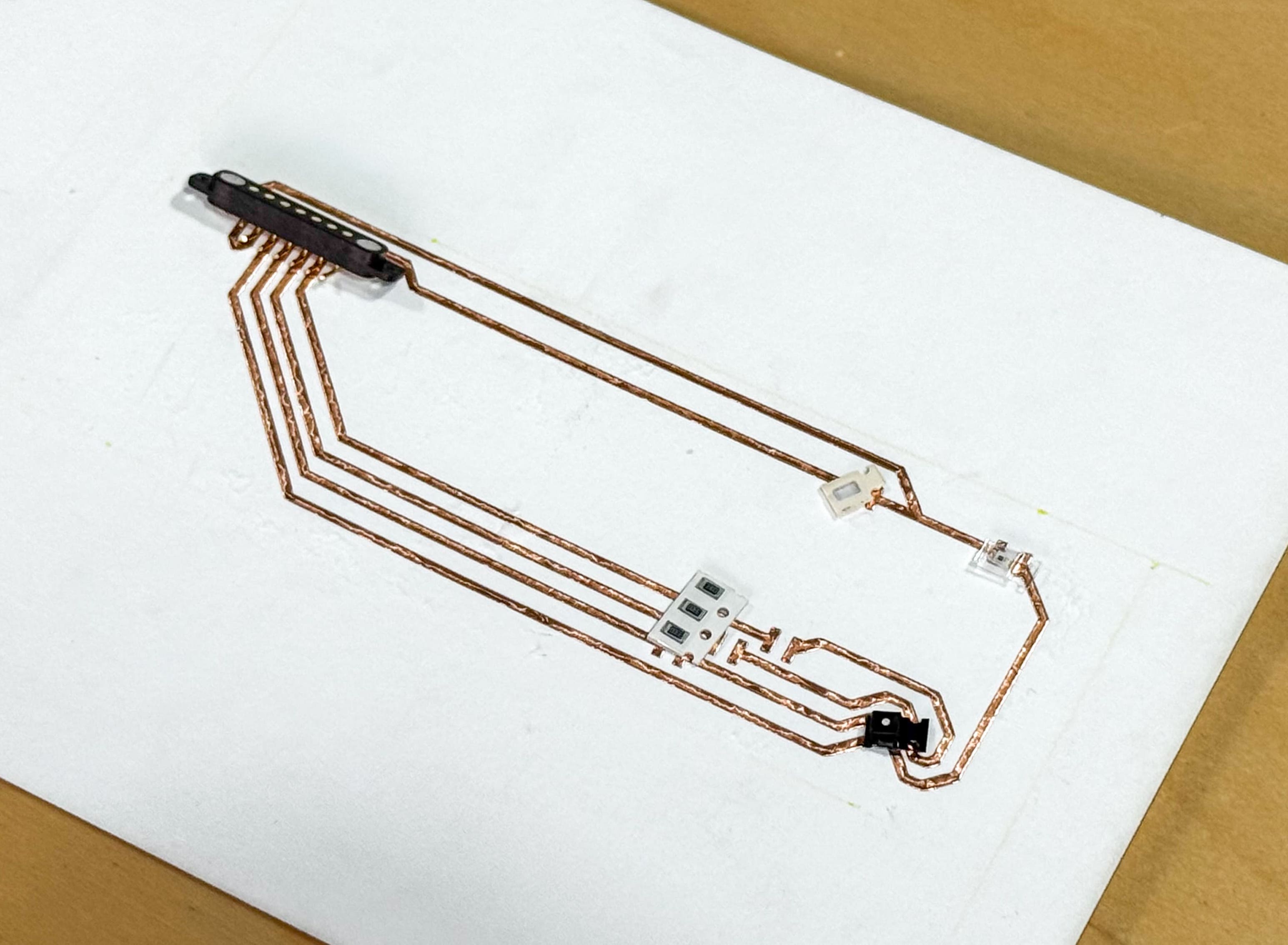
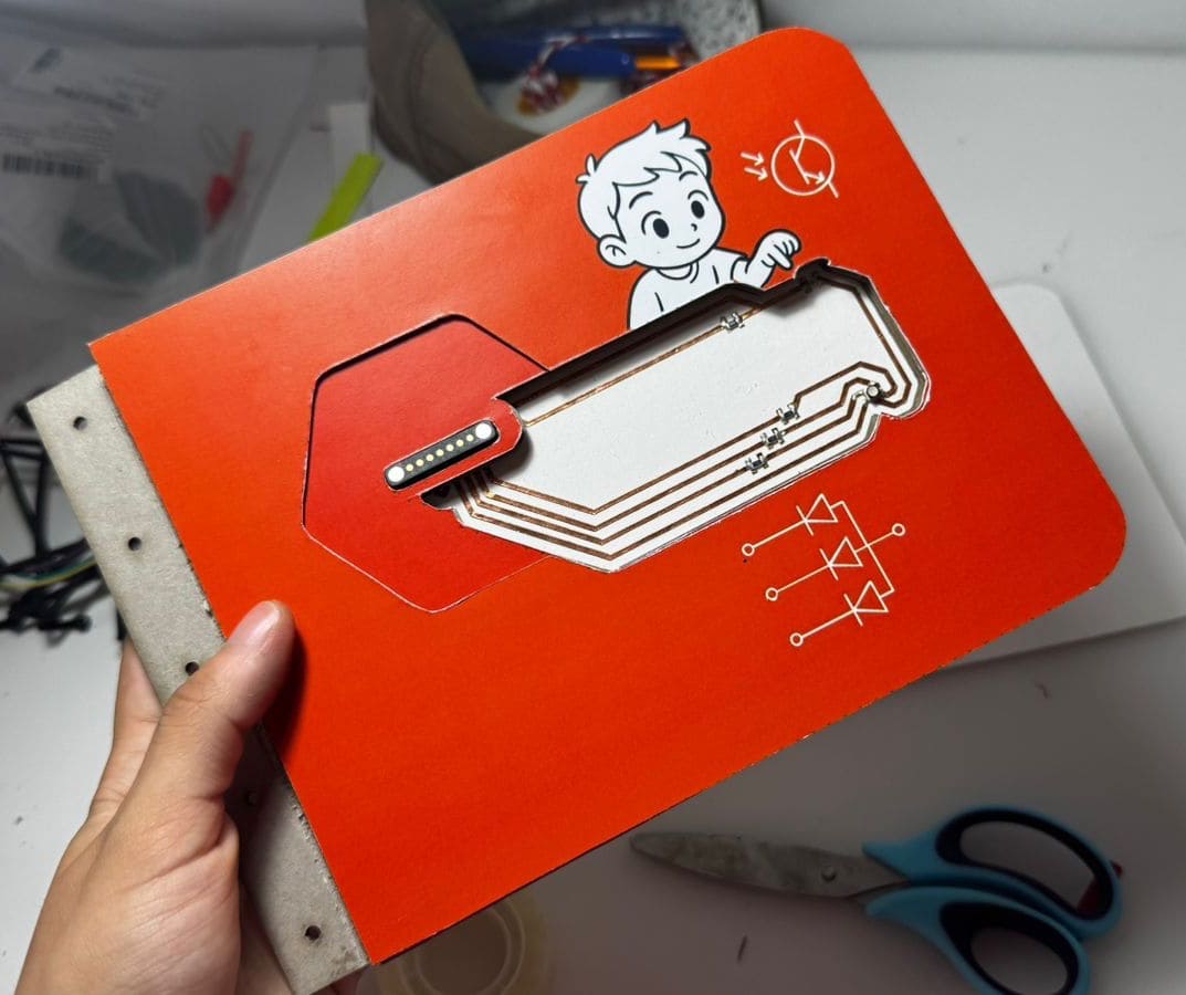
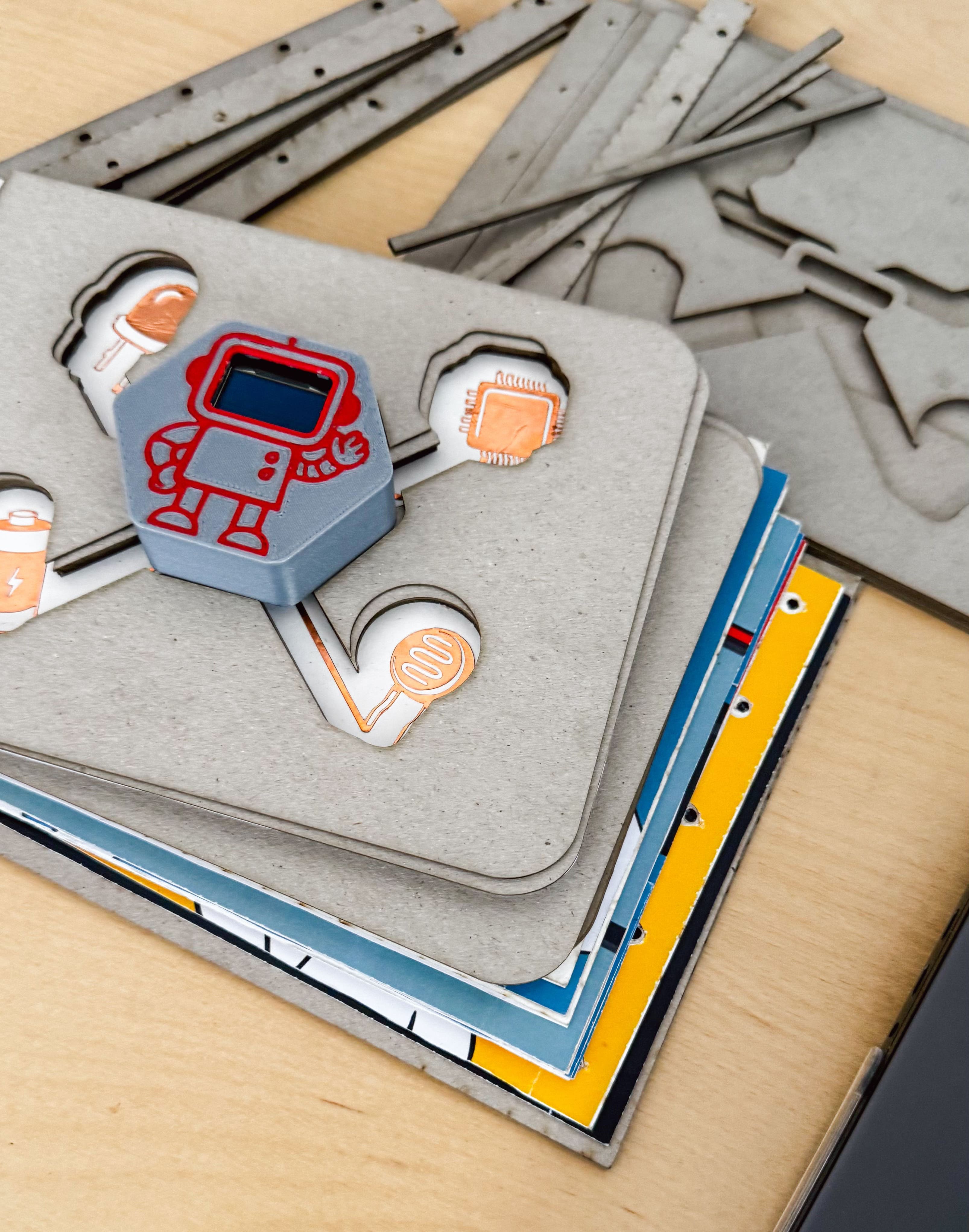
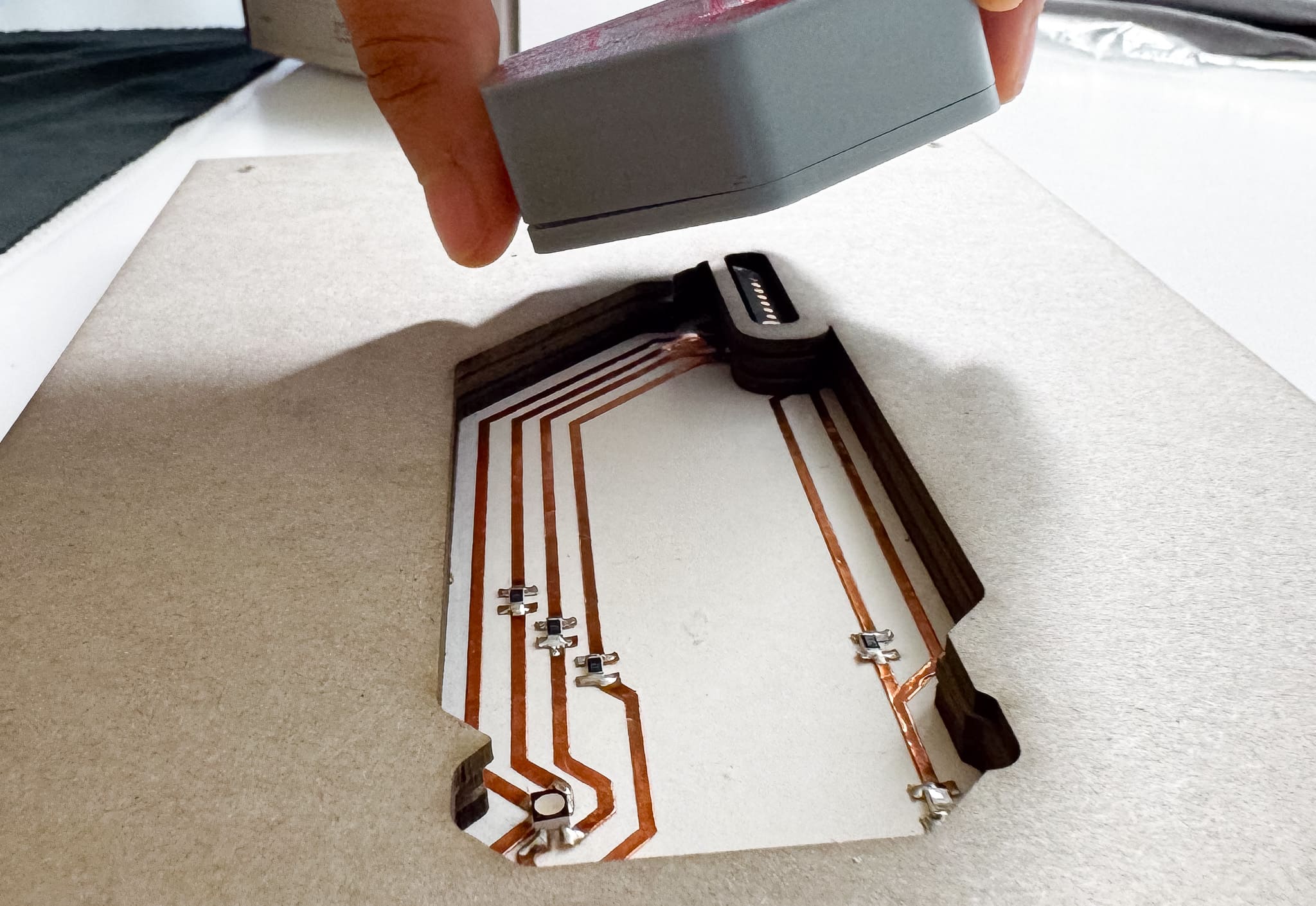
- Two interactive pages: RGB LED + Phototransistor with visual feedback and Touch pad with copper trace on acetate
- A 3D printed robot-style case and laser-cut acrylic housing
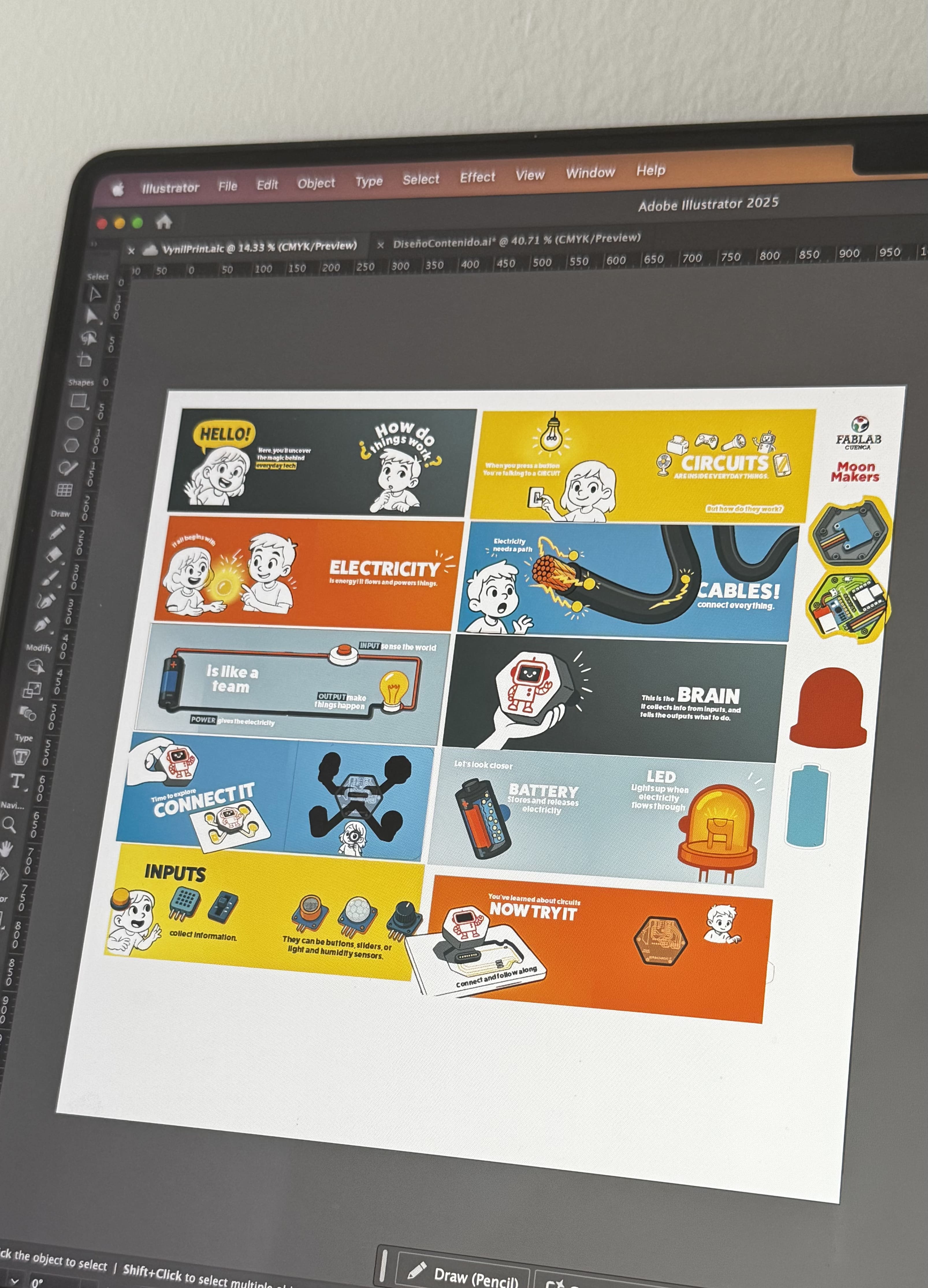
- Interface layout, graphic design and icons for each activity and page.
- Arduino code for interaction, sensor control, and feedback on OLED
What materials and components were used?, Where did they come from?, and How much did they cost?
Bill of Materials (BOM)
| Section | Item | Buy Link | Qty | Estimated Cost (€) |
|---|---|---|---|---|
| Main Board | Seeed XIAO ESP32-S3 | Seeed Studio | 1 | €7.00 |
| Li-Po Battery (3.7V 180mAh) | Adafruit | 1 | €5.95 | |
| GY-521 (MPU-6050) | Amazon | 1 | €4.90 | |
| OLED 128x64 Display (SSD1315) | AliExpress | 1 | €1.66 | |
| Magnetic Connectors | AliExpress | 3 | €4.80 | |
| Battery Connector to Board | — (included with battery) | 1 | — | |
| Female-to-Female Jumper Wires | Amazon | 4 | €1.00 | |
| Screws (for screen and board) | — | 6 | €1.00 | |
| Base Screws | — | 2 | €0.50 | |
| Interaction Page | LED RGB 4PLCC SMD | DigiKey | 1 | €0.44 |
| 330Ω Resistors | DigiKey | 3 | €0.27 | |
| Phototransistor IR 1206 | — | 1 | €0.09 | |
| 10kΩ Resistor | DigiKey | 1 | €0.10 | |
| Touch Pad (Copper on paper) | — (custom made with plotter) | 1 | — | |
| Fabrication | PLA Filament (Red + Grey) | Prusa | — | €4.00 |
| 5 mm Acrylic Sheet | — | 1 | €5.00 | |
| 1 cm Plywood Sheet | — | 1 | €5.00 | |
| 2 mm Cardboard (Reinforcement) | — (paper store) | 1 | €3.00 | |
| 250g Paper (Printing content) | — (paper store) | 24 | €6.00 | |
| 350g Paper (Circuit base) | — (paper store) | 6 | €5.00 | |
| Glue / Adhesive | — (paper store) | 1 | €1.00 | |
| Textile | Fabric (for embroidery cover) | — (recycled) | 1 | €2.00 |
| Threads (for embroidery) | — (5 colors used) | — | €2.00 | |
| 💬 Total Estimated Cost | — | — | — | ~60.71 (~$69.36 USD) |
What parts and systems were made?
- Fully assembled and tested main PCB
- Paper-based interactive circuits with sensors and outputs
- Modular connection system with magnetic pin
- Expression rendering system on OLED
- Embedded logic for each activity
- Laser-cut and 3D printed elements
- Housing and protective casing

What tools and processes were used?
| Requirement / Learning Outcome | How It Is Covered in the Project |
|---|---|
| 2D and 3D Design | I designed the 3D case for the main board using Fusion 360, including mounting points for the OLED and battery. The page layout and icons were designed in Illustrator. Circuit paths were created with KiCad. |
| Additive and Subtractive Fabrication | The housing board was milled using the CNC (subtractive) and acrylic parts for the cover . The case was printed in PLA (additive). I also used the plotter for the circuits in paper. The pages were laser-cut from thick paper, and the cover of the book was embroidered using a digital embroidery machine (Janome MB7), adding a textile fabrication component. |
| Electronics Design | I designed a custom PCB in KiCad integrating the ESP32-S3, headers, OLED connector, and a sensor. I also designed circuit layouts for each interactive page. |
| Electronics Production | I produced the first version of the board using the Fab Lab CNC mill and laser for the trace, and sent a second version to be manufactured via PCBWay. All components were soldered manually, including SMD and headers. |
| Embedded Microcontroller Interfacing | The ESP32S3 interfaces with the OLED via I2C, reads data from the MPU-6050 (GY-521), and reads analog inputs such as a phototransistor. |
| Embedded Programming | Using Arduino IDE, I programmed multiple behaviors: screen expressions, sensor reading, pin calibration, and RGB control. I also tested the system using the Serial Monitor and OLED feedback. |
| System Integration and Packaging | The main board connects via magnetic connectors to modular pages. The entire system is powered by a 3.7V LiPo battery and enclosed in a custom 3D printed case. Integration includes visual communication (OLED) and interactive pages |
Tools and Techniques Used:
- 2D design: Illustrator, Inkscape, LightBurn
- 3D modeling and printing: Fusion 360, Bambu Studio
- PCB design: KiCad
- Laser cutting: for the paper and cardboard pages
- Digital embroidery: Janome MB7 with Ink/Stitch
- Plotter: for applying copper-based circuits
- Electronics soldering: SMD components
- Embedded programming: Arduino IDE
What questions were answered?
One of the biggest questions was whether magnetic connectors would be a reliable method for attaching the modular interactive pages. The answer is yes: they worked great. The connections were secure, easy to align, and did not require fragile cables between pages.
Another key question was related to power consumption. The main board runs on a 3.7V LiPo battery (180 mAh), powering an ESP32-S3, an OLED screen, sensors like the GY-521 (MPU-6050), RGB LED, and touch/analog inputs. After multiple tests, it was confirmed that the system can run for short sessions (under 1 hour) before needing a recharge, which is reasonable for a demo or classroom setting. A future version could benefit from a higher capacity battery or sleep/power optimization modes.
Finally, the combination of interactive paper pages + electronics was also validated. It was not clear at first if the sensors and inputs would feel responsive or intuitive in the page format, but after testing different activities (like light), the result was smooth and well integrated.
What worked? What didn't?
✅ Worked:
- The magnetic modular system was easy to use and robust.
- The OLED screen interface and animated expressions were engaging and responsive.
- The touch inputs and light sensors worked correctly and added meaningful interaction.
- The 3D printed case had a good fit, as well the housing, especially with the transparent acrylic top.
- The embroidered cover gave a unique handmade finish to the book, merging digital fabrication with crafts.
❌ Didn’t work as expected:
- The MPU-6050 sensor was not fully functional due to soldering issues.
- The battery life was somewhat limited with 180 mAh, especially during longer testing sessions.
- One interactive page had unreliable readings due to poor copper contact, requiring pressure to work.
✅ What tasks have been completed?
- I designed and produced the main board using KiCad and CNC milling.
- I soldered all components and tested sensor readings and screen interactions.
- I created and printed the pages with touch and sensor circuits.
- I added magnetic connectors and tested modular page connections.
- I printed and assembled the 3D case using PLA.
- I laser-cut the components (pads, structures, pages).
- I embroidered the fabric cover of the book using the Janome MB7.
🕒 What tasks remain?
- Programmed the ESP32S3 to respond to inputs and give feedback via OLED.
- Completed the main visual and physical assembly of the book.
- Fine-tune some of the sensor thresholds for smoother interaction.
- Record a final demo video that shows how to use the book and what happens in each activity.
What will happen when?
- This week: Final adjustments and documentation polishing.
- Next few days: Record the final video walkthrough of the project.
- Before final presentation: Upload all final files to the Fab Academy repository and review checklist.
- Presentation day: Showcase the project and explain the design decisions, learnings, and results.
How was it evaluated?
Based on its ability to fulfill its educational purpose: teaching basic electronics through engaging, hands-on interaction. The combination of graphic elements, storytelling, and book format made the experience more approachable and enjoyable. The magnetic connections and modular pages provided a playful way to explore simple circuits, while the friendly design of the main board—like a companion—encouraged exploration across the book. Users could interact with each page and understand more about the role of each component.
What are the implications?
This project explores how electronics education can be transformed into a tangible, playful, and narrative experience. By merging digital fabrication with storytelling, kids (or beginners) can better grasp how sensors, microcontrollers, and interaction work—through a book, not a breadboard.
The modularity of the design means it can grow: new pages with different circuits or sensors could be created and added easily. The use of magnetic connectors simplifies hardware interaction, and the visual feedback via the OLED turns abstract data into meaningful experience.
This approach could be used in:
- Classrooms (for STEAM education)
- Museums or interactive exhibits
- DIY electronics kits
- Assistive educational tools for learners with different needs
It demonstrates that learning electronics doesn't have to start with code—it can start with curiosity, color, and connection.
What have you learned?
This project has helped me deepen my understanding of electronics design, embedded programming, and digital fabrication as a system—not just isolated skills. I learned how to make custom PCBs, calibrate sensors, and build modular, interactive circuits. I explored new tools like the embroidery machine and improved my documentation.
Dissemination Plan
I am creating Circuit Lab: How to Make (Almost) Any Circuit as an open and educational tool to help children explore basic electronics in a playful and intuitive way.
To protect and share my work:
- The code and hardware designs are released under the MIT License, allowing others to reuse, remix, and build upon them with proper credit.
- All educational content (text, interaction design, activities) is shared under Creative Commons Attribution-ShareAlike (CC BY-SA 4.0) to promote learning and adaptation.
- However, all original illustrations and graphics are protected by copyright (©) and may not be reused, modified, or redistributed without my explicit permission. These visual elements are part of my personal creative work.
This combination helps me protect the artistic identity of the project while encouraging open collaboration on the technical and educational aspects.
I plan to share this project widely through:
- My Fab Academy documentation site.
- Educational workshops and events through MoonMakers and Fab Labs.
In the future, I’d love to turn Circuit Lab into a STEAM education kit, ready to be tested in classrooms or fablabs. I also plan to keep improving the project based on feedback, and explore possible collaborations with others.
Future possibilities
This project started as a personal challenge to combine electronics, design, and education in a fun and accessible way. But I believe it can go much further.
In the future, I’d love to:
- Turn Circuit Lab into a educational kit that can be used in schools, Fab Labs, or at home.
- Develop a companion mobile app with interactive tutorials, animations, and even AR experiences linked to the pages.
- Run pilot workshops with children and educators to improve the design and content based on real feedback.
- Collaborate with nonprofits, educational programs, or other creators to adapt the content to different contexts and languages.
To make this happen, I plan to start with:
- Improving the design and flow of the book based on real feedback.
- Developing a first version of the mobile app with basic features.
- A small batch of test kits.
I created Circuit Lab to be modular, playful, and meaningful — and I’d love to keep creating, improving, and sharing it with others, so learning electronics can be creative, inclusive, and fun.