Embedded programming
| Owner | Oscar Diaz |
|---|
- Demonstrate and compare the toolchains and development workflows for available embedded architectures
- Document your work to the group work page and reflect on your individual page what you learned
About this week
Briefly describe the goal of the assignment. What are you characterizing, testing, or exploring
The group assignment for the Embedded Programming week is to compare multiple processors. This involves analyzing different microcontrollers in terms of their architecture, memory, peripherals, programming complexity, and performance. The goal is to understand the trade-offs between various families such as AVR, ARM, ESP32, and RP2040, and document findings based on benchmarks and real-world applications.
Tools and materials used
List all the machines, software and materials used in this assigment.
- THONNY IDE + Seed XIAO ESP32-C3 using MicroPython (Carl)
- Arduino IDE + Seeed XIAO RP2040 with the Seeed Studio XIAO expansion Board. (Diarmuid)
- BBC micro:bit + micro:bit Python IDE (Thom)
Process and methodology
Describe step-by-step what the group did. Include sketches, screenshots, or videos if possible.
THONNY IDE + Seed XIAO ESP32-C3 using MicroPython (Carl)
For my part of the group project i will be exploring using Thonny’s IDE to program on an ESP32 using MicroPython as my language. I have some mininal experiance in python so that was the driving factor in my decision as, apart from that i will be aproaching this week as a complete beginner.
Step 1: Thonny
Download Thonny from the below website and install it on your machine, in my case a M1 Macbook Pro
Step 2: Plug in your board by USB
Once you have conected your board you can navagate to the following menu in Thonny and select “MicroPython ESP32” from the drop down menu.
Tools -> Options -> Interperater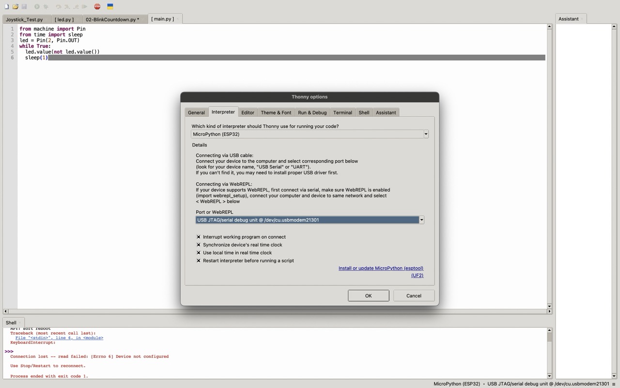
Then select your port, It will likely be the ones that ends in cu.modemxxxxx ←your serial number
Next use the menu to:
Install or update MicroPython (esptool)
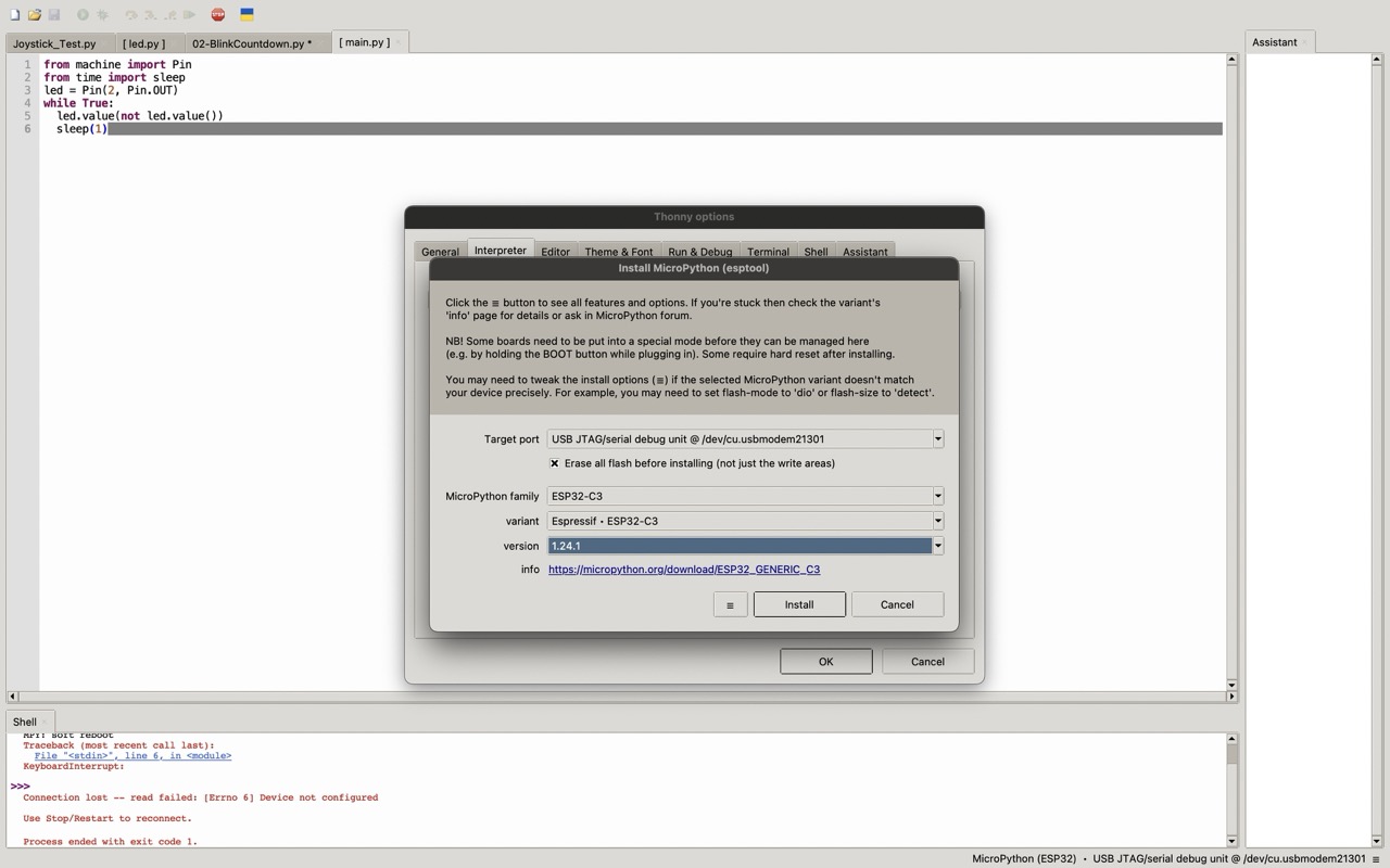
Fill in the values as above or if using a different board change accordingly. Then hit install and wait a few minutes. Thonny will now erase the the firmware board and flash the latest MicroPython firmware on your board.
When this is done close out of the menu and press the red Stop/Reset button on the top of the app.
If all is well you should now have the following text in your Shell on the bottom of the screen.
MicroPython v1.24.1 on 2024-11-29; ESP32C3 module with ESP32C3
Type "help()" for more information.
>>
Step 3: Testing on your ESP32
Once you have the Shell set up as above you can now start running python directly on your chip. To make sure things are doing well you can try some basic operations such as mathematical operations or print commands.
MicroPython v1.24.1 on 2024-11-29; ESP32C3 module with ESP32C3
Type "help()" for more information.
>> 1 + 1
2
>>
or
MicroPython v1.24.1 on 2024-11-29; ESP32C3 module with ESP32C3
Type "help()" for more information.
>> print("Hello world!")
Hello world!
Step 4: Make an LED blink using a breadboard.
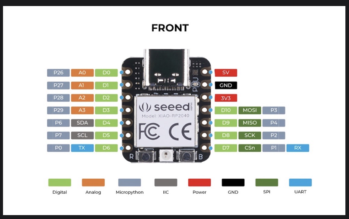
First step is to get your pinout diagram, mine was downloaded from Seeed studio, see below;
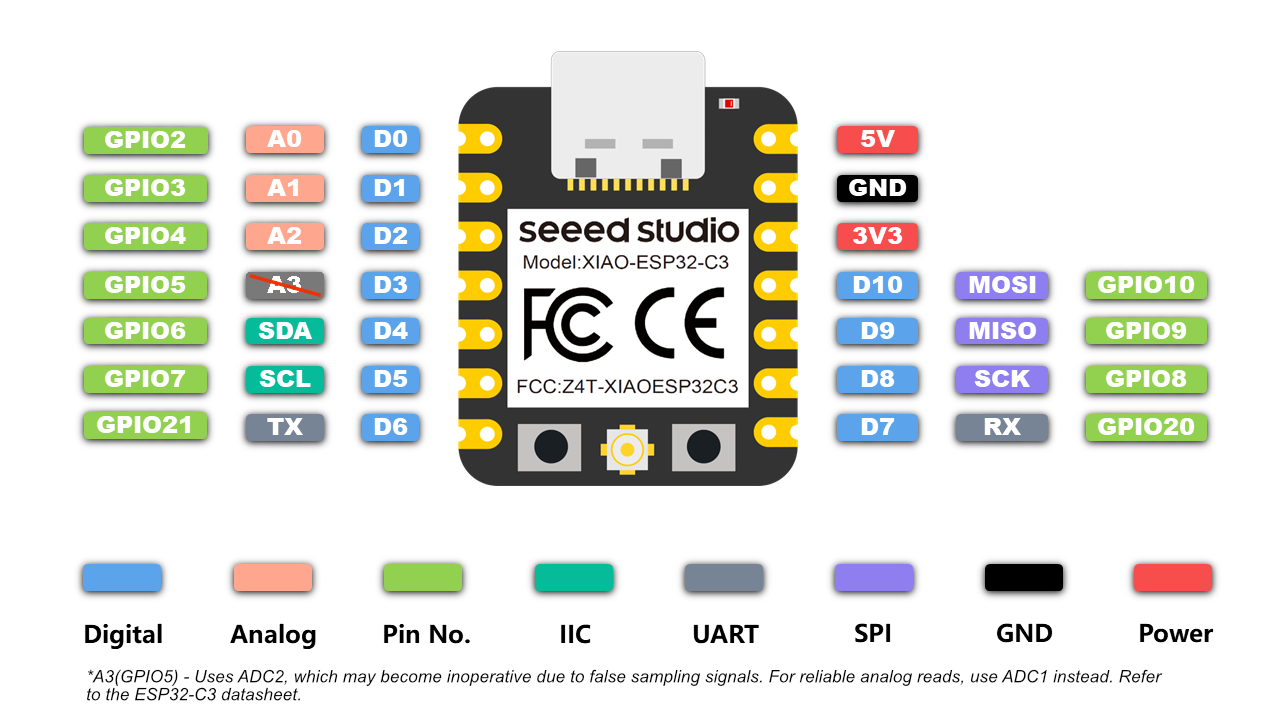
This shows me the names for each of the pins and any additional functionality they might have.
Note: Pay attention to the green values labeled GPIO as i got stuck for a while by using the D and A values. For example D0 in your program is listed as
Pin(2, Pin.OUT)This is because its reference is GPIO2
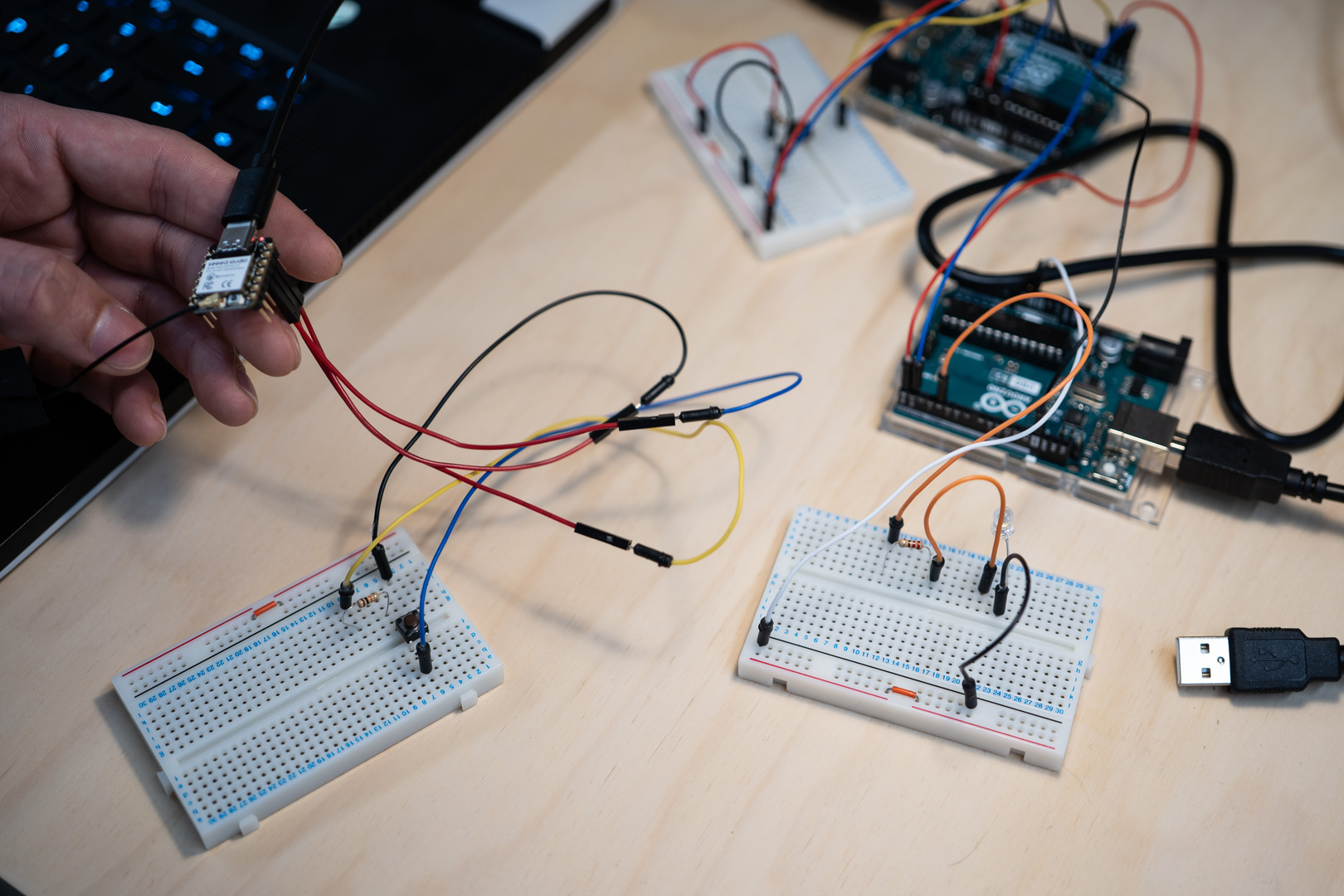
I set up my breadboard as below.
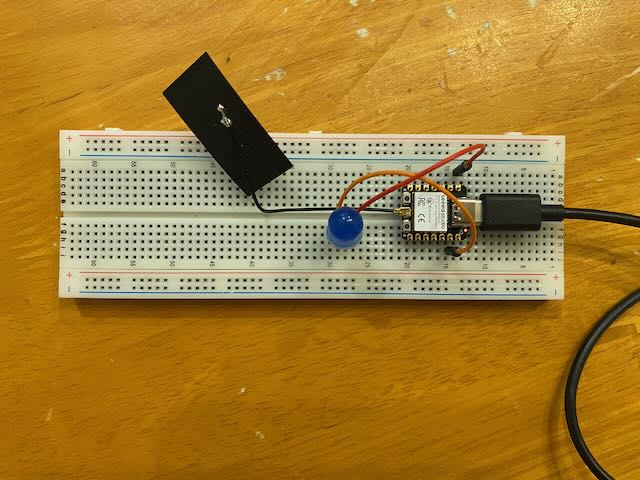
I have GPIO2 connected to the positive leg of an LED and i then have the negative leg of the led connected back to ground. (GND on the pinout)
With this setup i use the following code in Thonny.
from machine import Pin
from time import sleep
led = Pin(2, Pin.OUT)
while True:
  led.value(not led.value())
  sleep(1)
We can look at it line by line to see what is going on.
Importing modules
#From the module 'machine' import the function 'Pin'
#This allows us to talk to the board and reference the diferent pins
#based on ther GPIO numbers
from machine import Pin
#From the module 'time' import the function 'sleep'
#This module brings in the ability for python to keep time
#We will be using it to tell the program to wait inbetween each blink
from time import sleep
Setting Variables
#Here we set a variable 'led' to the value of the output of the
#pin called GPIO2
led = Pin(2, Pin.OUT)
Looping
#This creates and infinit loop for testing purposes, the program will run
#until it is told to stop
while True:
	#led.value() reads the current value of the variable led
	#not can be used invert a value
	#so led.value(not led.value()) reads the current value of led and then
	#sets it to the opposit
  led.value(not led.value())
  #asks the program to wait 1 second before looping again.
  sleep(1)
Success!
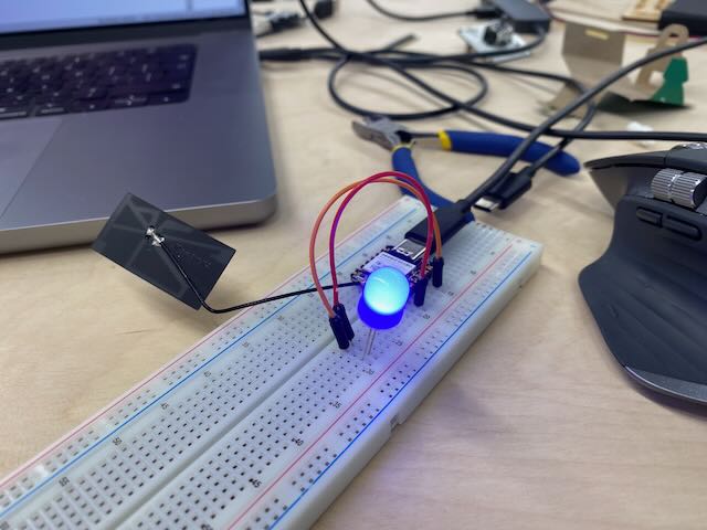
You are likely now feeling a rush of power and basking in the glow of both your own huge brain and the cool blue of the blinking LED. Take a moment to enjoy this.
Now that you have got yourself together…
Conclusions!
Though i am righting from a place of inexperience i have to say that i am very happy with this workflow.
Pro’s
The tools are very simple without all the layers of menus and options that i see in the bigger IDE’s that can be very intimidating for beginner.
While it may well be possible that i will outgrow this workflow someday and will need more advanced tools, for a beginner i can definitely recommend it.
Con’s
There were moments where i was running into issues and its possible the a more advanced IDE would be able to give me more guidance as to what was going wrong, for example for a long time i was connected to the wrong pin as i was using the D0 value rather than GPIO2 in my code. More precise error messages or something to tell me that the Pin that i was calling wasn't connected to anything would have been nice
A small complaint with the ESP32-C3 from Xiao is that i could not find a way to use the onboard led for testing a blink program. So this meant that i needed to jump straight into learning how to use a breadboard. Although this is likely now good experience, having a onboard LED is a very nice and standard way for a beginner to see the code on there screen generating an output on the device.
Overall
Despite the cons looking longer then the pros word count wise i am very happy with this workflow and will likely stick with it as i build out more of the details around my final project.
Arduino IDE + Seeed XIAO RP2040 with the Seeed Studio XIAO expansion Board. (Diarmuid)
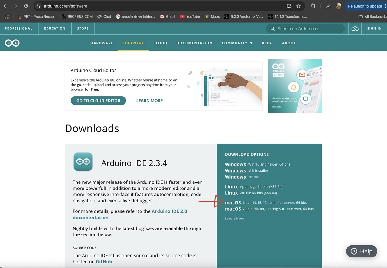
Looking at Arduino IDE and the Seeed XIAO RP2040 with the Seeed Studio XIAO expansion Board. Start by Download the Arduino IDE use the link below.
https://www.arduino.cc/en/software

Go to the arduino.cc website, navigate to the software page and download your appropriate operating system flavour. Mac OS Intel in my case.
Click just download (or make a donation if you’re feeling generous)
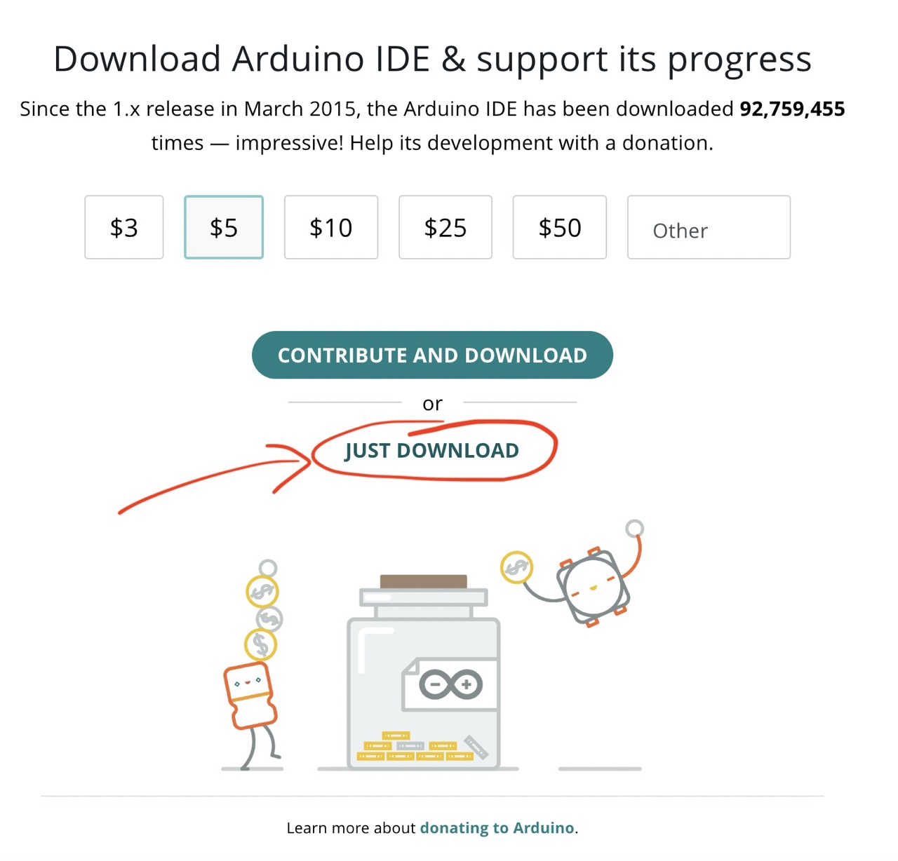
And again Just download (or add an email if you want updates)

Open you downloads folder and open the downloaded Arduino installer.

drag the Arduino Icon to the applications folder.
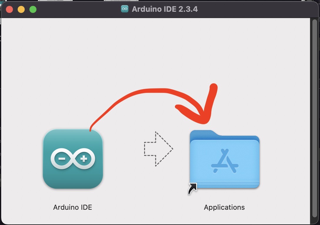
Arduino IDE has been installed – congratulations!!
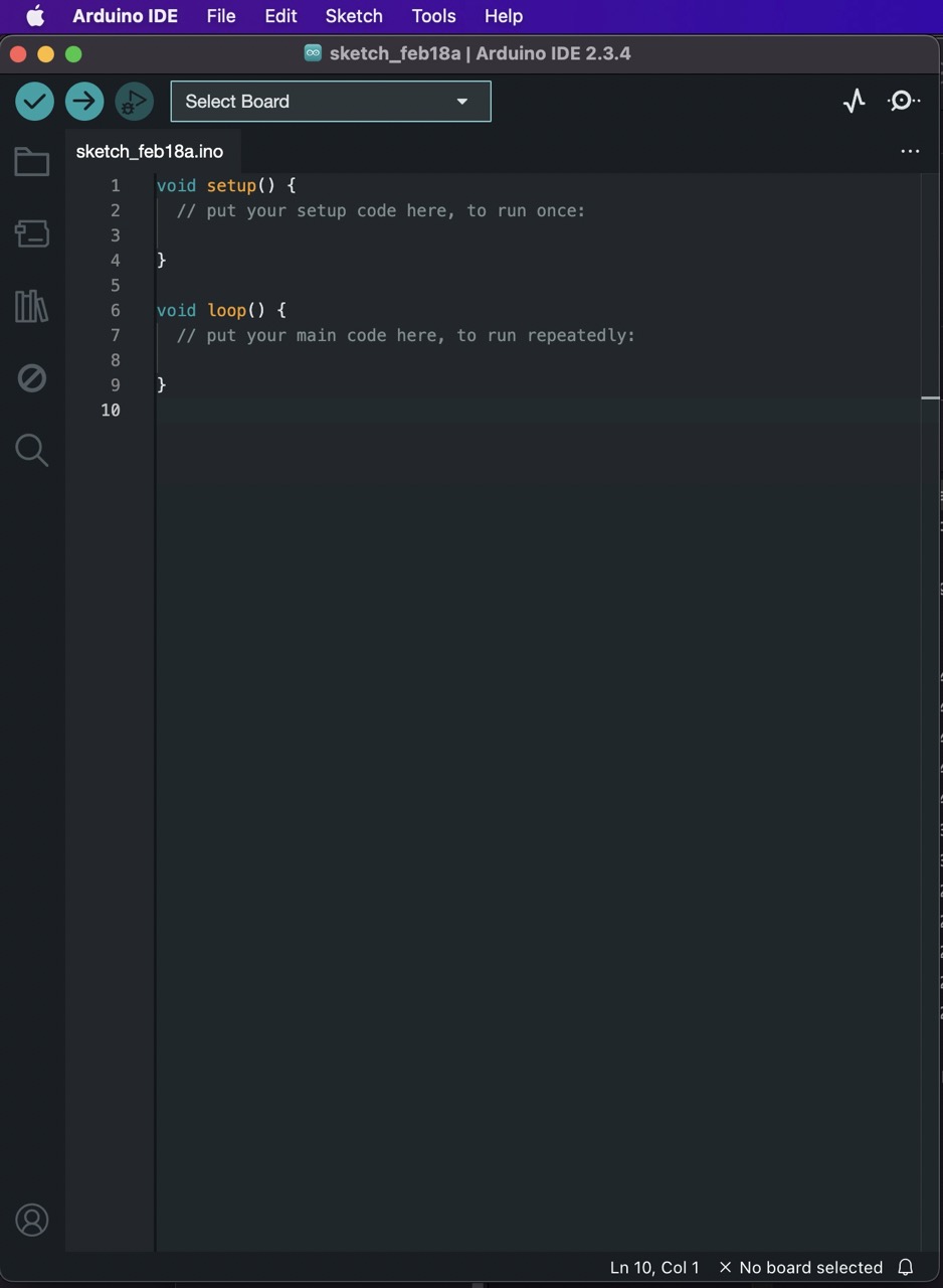
This should be the screen we see when we open Arduino IDE
As we are going to be using the Seeed Studio XIAO RP2040 there are a few more bits we need to installed to be able to use the board with the Arduin IDE
We went to Seeed Studio wiki to learn more.
https://wiki.seeedstudio.com/XIAO-RP2040/
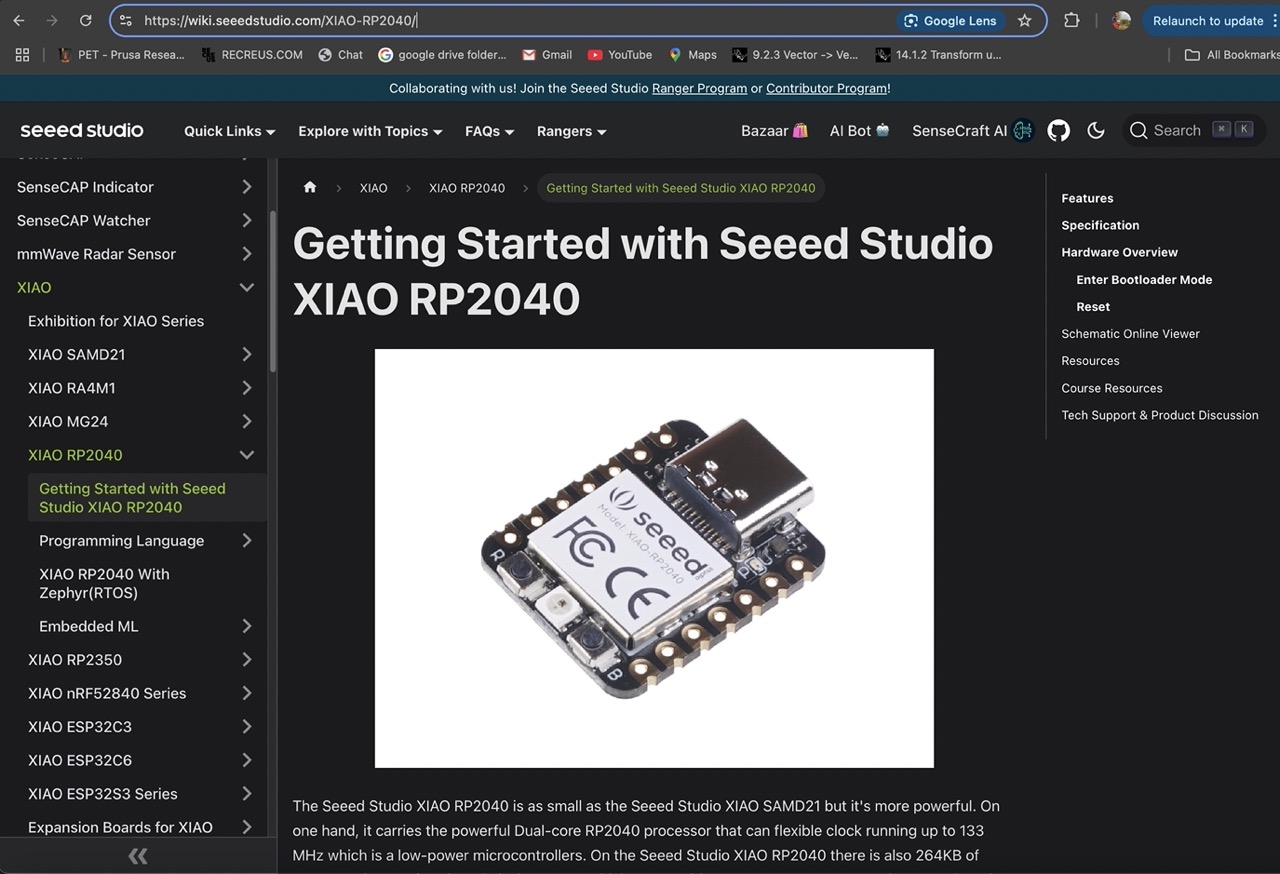
This website gives basic overview of the RP 2040 below we can see the basic components if the board.
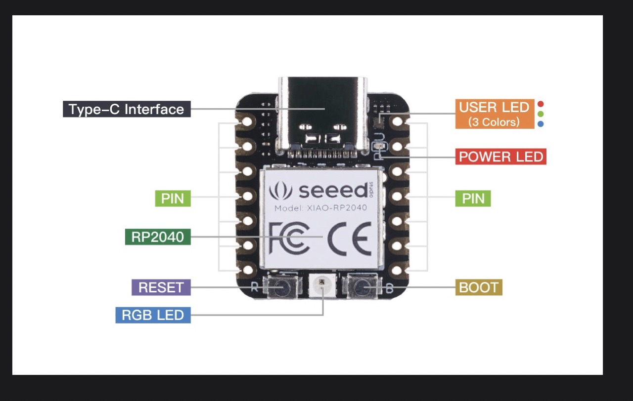
below are detail of the pinouts for the XIAO-PR2040
A few things to be mindful how to enter Boot loader Mode and how to reset direct from the website.
Sometimes the Seeed Studio XIAO RP2040 port may disappear when user programming process fails. we can solve this problem by the following operation:
Long press the "B" button.
Connect the Seeed Studio XIAO PR2040 to your computer.
The computer will appear a disk driver.
At this point, the chip enters Bootloader mode and the burn port appears again. Because the RP2040 chip has two partitions, one is the Bootloader and the other is the user program. The product will burn a bootloader code in the system memory when it leaves the factory. We can switch modes by performing the above steps.
If you want to reset the Seeed Studio XIAO RP2040, perform the following steps:
Connect the Seeed Studio XIAO RP2040 to your computer.
Press the "R" pins once.
Please note: The behavior of the built-in programmable Single-colour LEDs (They are red, blue and green) are reversed to the one on an Arduino. On the Seeed Studio XIAO RP2040, the pin has to be pulled low to enable.
At the bottom of this page you will find a link to the ebook XIAO Big Power Small Board
https://mjrovai.github.io/XIAO_Big_Power_Small_Board-ebook/

We went through this for getting started with the XIAO and it is also where we got the links to download the necessary programmes or add-in’s for Arduino.
See section 1.1.2
In my case I am installing the RP2040 files you can also find ESP32C3 links also.
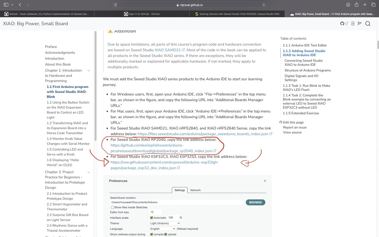
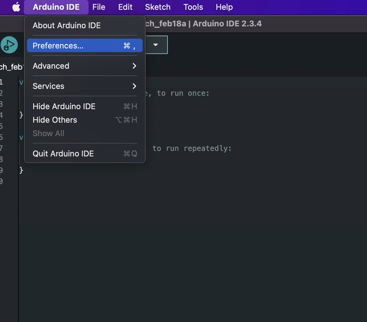
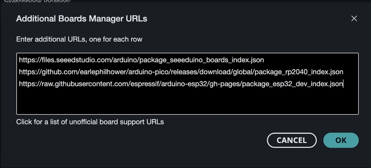
To install these copy the link go to Arduino IDE preferences.
Paste the link into the additional boards manager section
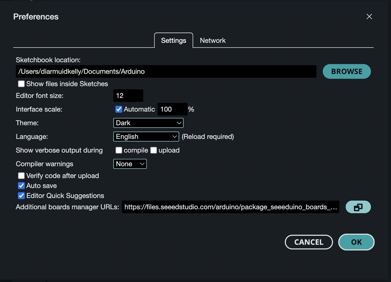
As we have more than one link we can click the button to the right which allows us to add more than one link.
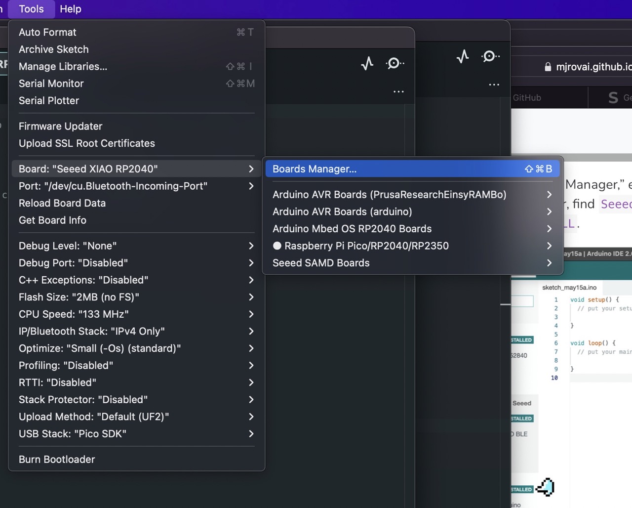
Next we need to add the boards in the board manager. Under tools> board> boards manager
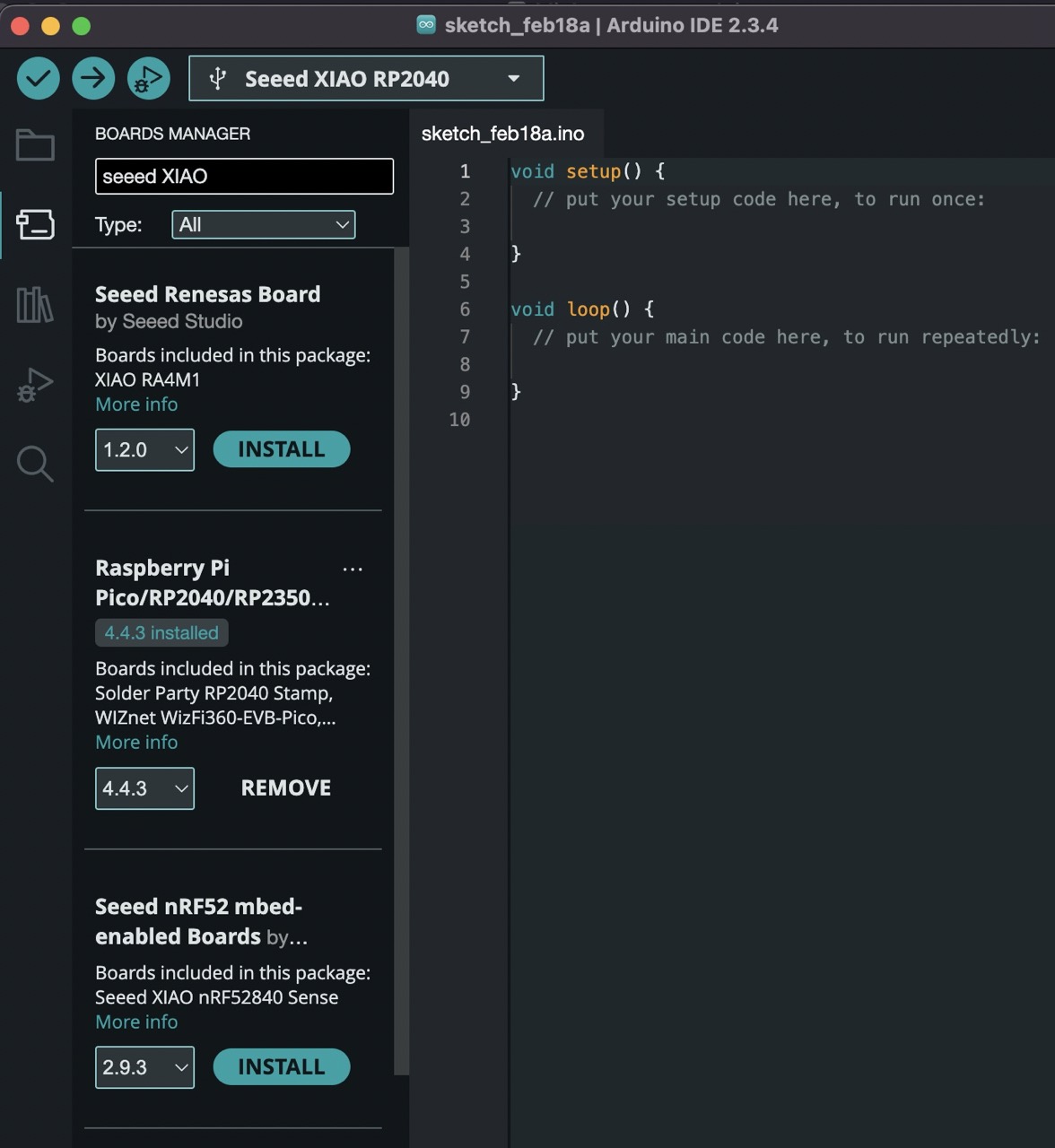
Search Seeed XIAO and find the Raspberry Pi Pico/RP2040/RP2350 and click install – once installed it should look like the image below and tell you that it is installed.
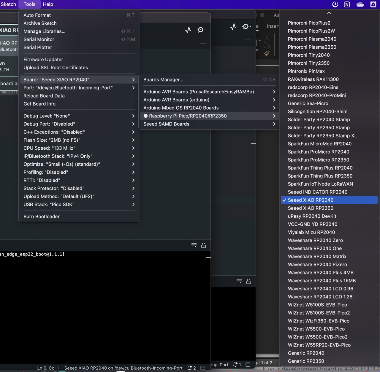
We can now select the RP2040 board Tools> boards> Raspberry pi Pico/RP2040/RP2350 and scroll down until you get to the Seeed RP2040
Connect the board to the computer with USB C cable, We need to select the
board from the drop down it should be something like the image below unconfirmed board usbmodem or similar – it should at least have USB somewhere in the name.
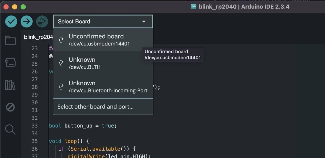
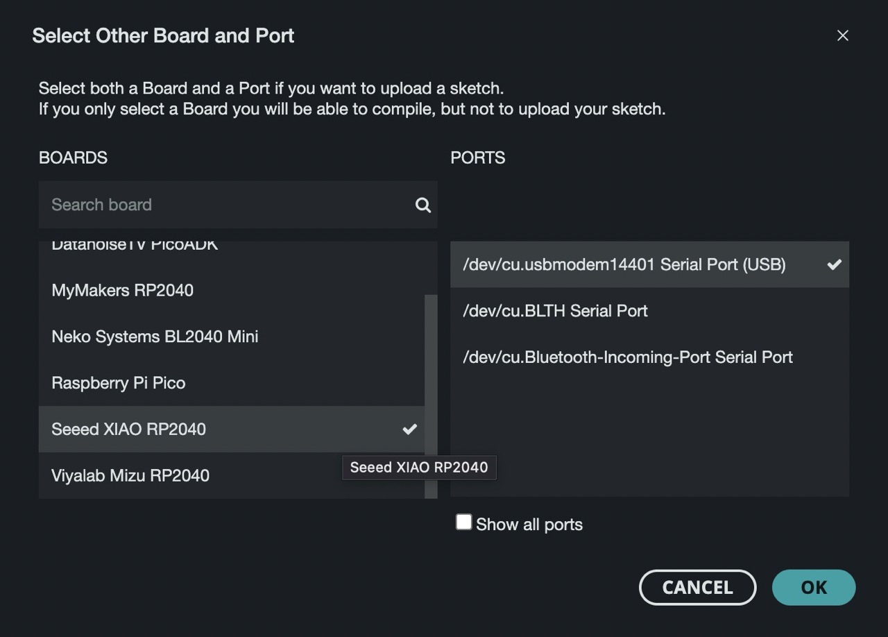
We may need to tell Arduino what board is connected. See image below.
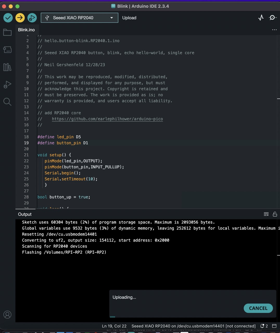
Finally…. lets start with simple code sample - I’m going to use Niels sample code for this link below.
https://academy.cba.mit.edu/classes/embedded_programming/RP2040/hello.button-blink.RP2040.1.ino
copy and paste this code into the Arduion IDE

As we are using the Seeed Studio XIAO Expansion Board here is the relevant pinout diagram.
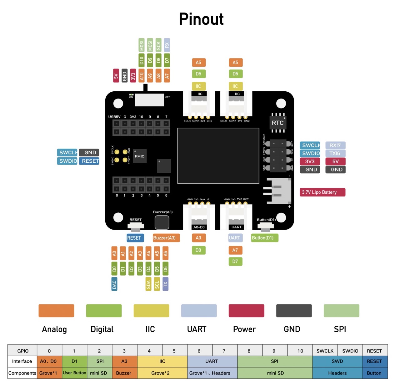
I need to make some changes to Neil’s code for the correct pinouts
led_pin 1 is changed to D5 and button_pin 0 changed to D1

Verify the code (tick button top left of Arduino IDE)
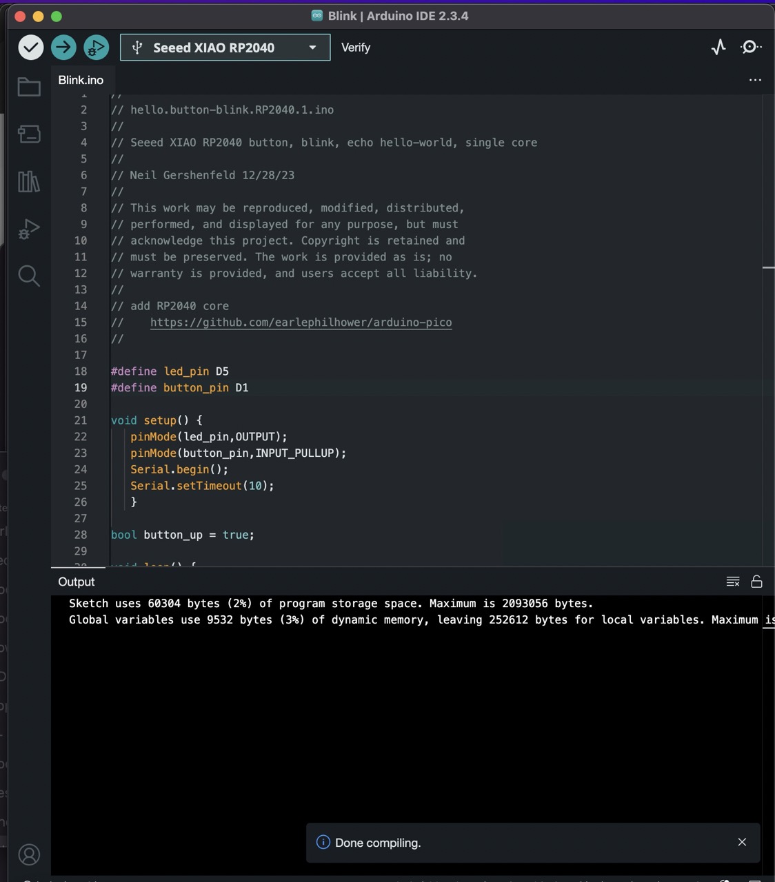
and upload the code to the board (right arrow top left of Arduino IDE)
We can now press the button bottom right of the Expansion board to switch on and off the led.
Thom Conaty - Week 4 Group Assignment:
BBC micro:bit + Microsoft (micro:bit) Python IDE
0.Introduction
The micro:bit is a pocket-sized computer designed by the BBC for use in computer education. Originally created for UK schools to inspire digital creativity in young people, it has become a global educational tool ideal for students aged 8-16 years old and beginners in programming and electronics.
Key strengths:
- Educational Focus - Designed specifically for learning, with an intuitive interface and gradual learning curve
- Immediate Feedback - Built-in LED display and sensors provide instant visual feedback for code execution
- No Setup Required - Works straight out of the box with web-based programming interface
- Robust Design - Durable construction suitable for classroom environments and young users
- Progressive Learning Path - Supports transition from block-based to text-based programming
- Affordable - Cost-effective solution for schools and individual learners
Key features include:
- Nordic nRF52833 processor with Bluetooth 5.1 BLE - A general-purpose multiprotocol SoC with a Bluetooth Direction Finding capable radio, qualified for operation at an extended temperature range of -40°C to 105°C. It is the 5th addition to the industry leading nRF52 Series and is built around a 64 MHz Arm Cortex-M4 with FPU, and has 512 KB flash and 128 KB RAM memory available for higher value applications.
- 25 LED matrix display
- 2 programmable buttons
- Motion sensors (accelerometer and compass)
- Temperature and light sensors
- Edge connector with large pins for external connections
- USB interface for programming
Programming Options
- Microsoft MakeCode - Block-based and JavaScript programming environment
- Python (via MicroPython) - For text-based programming
- Scratch integration - Familiar environment for young coders
Educational Resources
- Complete, editable computing units for ages 7-11
- Advanced projects for ages 11-14 covering computing fundamentals, cyber security, and cryptography
- Cross-curricular links for art, science, and geography
- Global sustainability and problem-solving projects
How to use the BBC micro:bit with Python
[Note: Demo code and Nordic nRF52833 processor Datasheet at bottom of document]
- Setup
Visit Python Editor for micro:bit to access the cloud-based Microsoft Python Editor
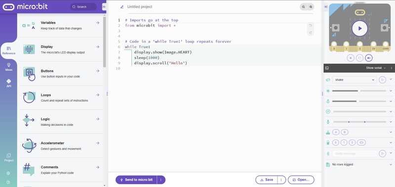
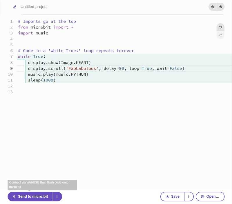
Step 2: Writing Code
The IDE facilitates developing patches in Python and communication with the micro:bit: This Python code creates an interactive program that scrolls a message and plays music:
Step 3: Testing the IDE Simulator
Before uploading to the physical device, we can test our code in the built-in simulator:
Step 4: Testing on the micro:bit
Connect your micro:bit to your computer using the supplied USB cable. The LED matrix will light up, indicating that the device is powered on. Once connected, follow these steps:
- Click the 'Connect' button to pair with your micro:bit
- Click 'Send to micro:bit' to flash the code
- Press button A to see the message scroll and hear the tune
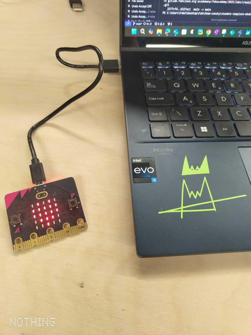
Step Fun: Microbit in action!
Group conclusions
Findings: [What did you learn from the process?]
How to programme with Arduino IDE, the vast range of microcontrollers that are out there and
Challenges: [What issues did you encounter?]
Issues with install of Arduino after a few days it would not compile on my mac - I suspect iCloud drive was the issue - pushing the Arduino folder to the cloud and libraries not getting pulled when neeeded - I will monitor this.
Solutions: [How did you solve them?]
For the compiling issue on the Mac I deleted Arduino IDE and the Arduino folder in Documents - and reinstalled everything - this worked will monitor how it goes over the next few weeks - I would like to be able to get the Arduino folder in my Mac to stay on my Mac permanently - any idea how to do this?
Files
Add all files created for this group assignment
See below link to to files created this week: