Week 3 - Computer Controlled Cutting
In this week, I designed and cut a Vinyl Sticker. Then, I worked on the group assignment. Lastly, I created a parametric construction kit.
In computer controlled cutting, kerf is an important term. But what is it? Well, kerf is essentially the the width of a cut that is made when cutting an object. So for example, if I cut a piece of cardboard with a laser that had a width of 0.5mm, then the kerf would be 0.5mm. This is a small number to worry about, but when using large machinery like a ShopBot, it is very much important to consider when designing and cutting.
In manual cutting, because if I were to take a saw and cut along a line that I had drawn, I would have to make sure that the edge of the saw was on the outside of the shape I want because cutting with the center of the saw along the center of the line would result in a loss of material in the shape I want, resulting in disproportionate pieces.
Vinyl Sticker
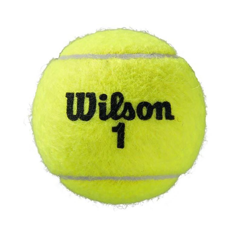
To create my Vinyl Sticker, I first found my muse: a Wilson tennis ball.
After choosing my image, I removed the background using remove.bg.
I opened CorelDRAW and imported the image into a new project and using the Trace Bitmap tool on the top, I attempted to use the logo converter but it would't get the outlines to include the rubber lines of the ball without the detail becoming too high.
 So I ended up just using the B-spline tool to trace the ball.

After manually "converting," I changed all the lines to hairline before exporting to Silhouette Studio as an SVG.
Then, in Silhouette Studio, I imported the file. With the help of Tyler Russel, I successfully navigated Silhouette Studio quickly and cut it out on the vinyl cutter. He also gave me instructions on how to create a multicolored vinyl sticker: by creating cutouts of each color and transferring each part one by one onto one piece of tape. Here are some pictures of the sticker-making process.
First, I loaded the vinyl in.

Then, I clicked send on Silhouette Studio and the vinyl cutter did its thing.
After I had repeated this process for all three colors: yellow, black, and white. These are the results of each piece after I "weeded" out the excess vinyl.


After they had all been weeded, I meticulously transferred all of them onto one single cutout of transfer tape.
![]()
After that, the only thing left to do was to stick it onto our school's fab academy window of stickers. I did this by putting the sticker on the window after it had been cleaned and then I used the squeegee to push out all of the air holes. If I were to do this again, I would probably be more careful when putting the sticker on since there is still some air that could not be removed after I had fully stuck it on.

Group Project
Our group project for this week was to test out our laser cutters using different tests. Here is the website where that can be seen. On this project, I was tasked to do the Joint Clearance Testing.
Parametric Construction Kit
The last task I had this week was to create a parametric construction kit. It is a construction kit that can be used to make different shapes and objects, but the most key feature is that it is parametric, so the size of the pieces can be readjusted without much effort.
I decided to use Fusion 360's sketch feature to design my kit.
At first, I didn't really know what parametric design was, so I searched youtube in search for an answer and then I stumbled upon this video. This video was very helpful because it taught me how to use the parametric modeling in fusion 360 while also explaining why parametric modeling is helpful.
Then, with some guidance from Tyler Russel again and a little bit of struggling with constraints, I created this behemoth.

To create this, I made a hexagon using the polygon tool and then assigned the diameter to hexagon_diameter. Then, I made contruction lines running from the center of each side to the opposite. To create the slots, I made a rectangle split in half by one of the construction lines that had cardboard_width assigned to one of the sides. I then used the circular pattern tool and made it go around the hexagon. To do the chamfer, I simply selected the equal distance chamfer tool and modified each corner going into the slot. Finally, I removed the excess lines.
The beauty of parametric modeling is that using the "change parameters" tool, if I change one of the variables I had defined beforehand, I any sketch of that will obey that change. Here are some of the parameters that I set.

Using the hexagon_diameter parameter, I created 2 different versions, one bigger than the other, but thanks to my constraints, the only thing that changed was the overall size. The width of the slots was never changed because I needed to keep it at the cardboard width.
In case I ever needed to change the value of the chamfer because it was too large or not large enough, then I could and it would allow the cardboard pieces to move together easier.
The cardboard width allowed me to change the width of the material I was using. Although I did not do this, but I could potentially use this on different thickness cardboard and each shape would still be able to fit together.
I then, imported these two designs as DXF files into CorelDraw to prepare it for laser cutting. All I did was resize it to its original lengths and check with the measure tool to see if the slots were the right widths, and then I cut it using our lab's pre-set cardboard settings.
After I just randomly put together my pieces, here is the result.

As you can see, all the pieces, big or small, fit together perfectly because of the parametric modeling tool in Fusion 360.
If I were to do this again, I would spend more time figuring out a certain shape or image I could make from combining the shapes. I would also try to explore using rectangles, triangles, and more instead of just a hexagon.
Reflection
In this week, I thought it was pretty fun because our whole lab's students were making their own vinyl stickers, each one unique. I had made vinyl stickers in the past, but making one's that were multicolored was cool. It was also cool how I could use parametrics to change any variable I make and it would automatically apply to all the things I wanted. The group project also made me realize the different nuances in computer controlled cutting that I need to think about when doing so.