Concept
Planning
My final project is a mini-golf course with automated features and obstacles made from CAD. I intend to base this off of the Raintree North Course hole 7, a par 5 featuring bunkers, lakes, and a cart path.
I need a wooden base, laser-cut, covered in AstroTurf. The tee box would require an additional layer, otherwise, one could place the ball wherever. Adding multiple would over complicate the process.
The cart path would not be AstroTurf, although I could find a bit of granite or similar to add to the immersion. Would that be enough? Typically, golf carts ride along these paths, and the additional threat of hitting one - on the opening shot, no less – would help greatly. The next question is how to make this. It would likely involve 3D printing, motors, PCB insertion, and simple programming to move back and forth. It would not need to reverse, just U-turn at the end, possibly stopping for an easier game.
For the path itself, I need some variance. The offside bunker helps, but for mini-golf, adding slope and divots is necessary.
Now, the lake. This requires, not just laser cutting, but likely woodwork. I would possibly saw the base in order to create an extended, precise lake. I would pour water into this. Stagnant water’s no fun, so another opportunity lies in a spinning mechanism to churn the water. If one can create a windmill for mini-golf, this should not be a problem.
I would likely need a bridge, which leaves me three choices. I could 3D print a narrow, intricate bridge across the lake for the ball to follow. I could print or cut a simpler but more challenging drawbridge programmed to rise and fall at certain intervals. Miss the drawbridge and fall. I could technically stay true to the inspiration and not have a bridge, which would involve adding a slope for the player to chip the ball. After considering this, it would be a bit risky and unnecessarily complicated. Some putters are more receptive to chipping than others, so I’ll eliminate this.
I visited a mini golf course a while ago for an event, and the course incorporates more elements like the drawbridge. The alternative is more luck-based and ornate. I may change my mind on this later, but a drawbridge seems ideal.
The side bunkers, much like the fairway bunkers, would involve pouring sand in smaller holes in the base. I’m unsure how difficult this would be.
Last, the green. This would entail 3D printing a removable flag and drilling a hole in, large enough for a standard golf ball. I may or may not incorporate the concept of pin position, or the ability to place the hole in different spots, into the project. While this seems doable by drilling multiple and using wooden insertions to replace the holes, would it be worth it? The alternative would be keeping one spot in the center and possibly programming it to congratulate you when the ball lands in the pin. This would be less complicated and lead to a smoother green. Also, more electrical engineering, and of course choosing a soundtrack.
I researched the average dimensions for a short but playable mini-golf course. I found that 4-5 feet per turn is enough room. Any less would be difficult to play on, and any more would be beyond the scope of this project. These are very tentative dimensions.
To summarize, I plan to add a golf cart that moves along a cart path, an automated drawbridge across the lake, and a small mill to make the lake water flow.
Sketch
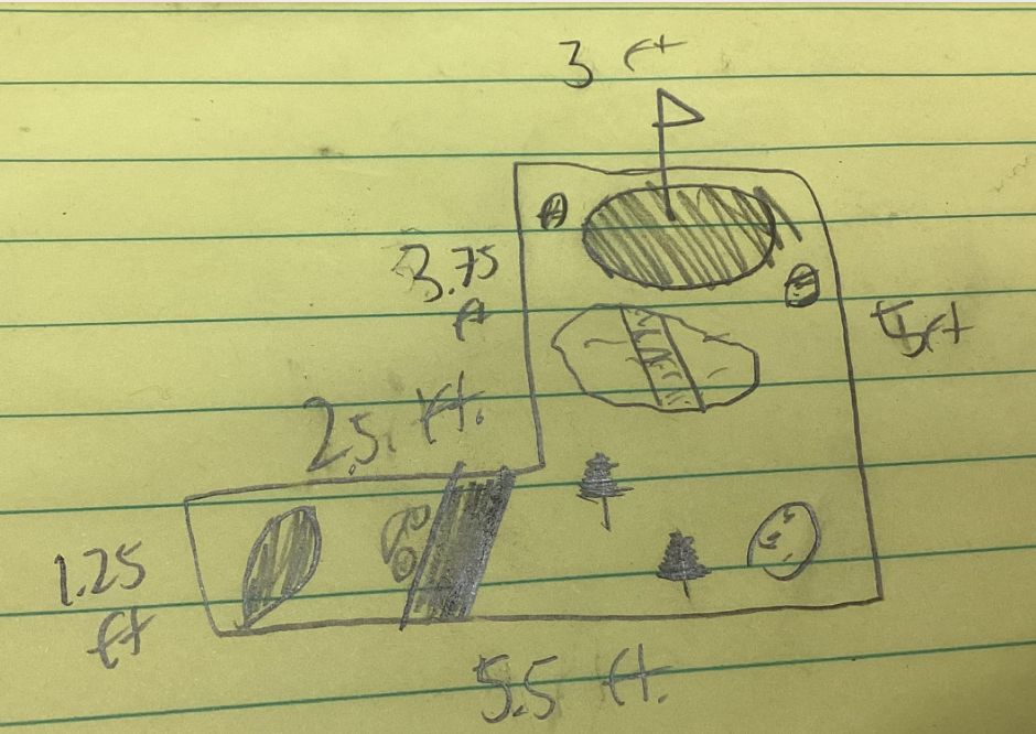
I planned my final project prior to the beginning of Fab Academy and have a rough sketch in Notability. Since it is different from my original idea, I will confirm this with my teachers next week.
My project is a mini-golf course inspired by Raintree, a country club near us, with electrical components. I chose #7 on the North Course due to its variety of elements and room for experimentation. The course also includes a sharp turn, which will add to the challenge. This game could potentially be sold for golf enthusiasts to practice during their free time, or as entertainment at events.
I sketched a model for my final project. In doing so, I determined the components that my final project would ideally have.
 }{ width=250px
I created a basic sketch of the course layout and the design of the surface. This was the reference I used for 2D and 3D models.

CAD
2D Design
Initially, I created a simple CorelDraw model of the course. I would most likely adapt this to include fillets and press-fits, likely through re-creating a 2D sketch in Fusion 360.

3D Design
General
I made a very general 3D model of the course. I would not transfer it to anything, it is simply a 3D sketch. I included extrusions, both cut into the course for lakes/bunkers and upwards for the tee box and green. The nuances such as the cart path, which is typically a slight groove, would most likely be done using the shop bot.
I also imported the programmed golf cart. I do not have the other two elements in this iteration.

Bridge
Tutorial
To prepare for 3D printing week, I figured sketching another part of my project model would make sense.
I followed a tutorial to make a bridge in Fusion 360.

Converting to Drawbridge
While I had a workable bridge, I needed a drawbridge. Before I determine the mechanics, I would need to phyically split the bridge. I’ll also add a bit more detail.
- Split bridge
- Extrude middle column through the top
-
Cut remaining pieces in other directions

-
Vertical mirror extrusion
- Create plane on face at point for center of bridge
-
Mirror across plane

-
Extrusions
- Cut intersecting face away
- Cut vertical columns above the face
-
Extrude top of colunms down to the same height

-
Trim
- Extrude down to .25 inches
- Apply two-side extrusion horizontally

This still needs polishing in terms of dimensions, but has proportional parts and a workable starting shape.
ShopBot Design
I made a design that I intend to mill on the Shopbot. I would use a tablesaw to cut out dowels and connect the layers. This would ensure a proper fit without complicating the design.
Planning
It occured to me that I could modify a .dxf file for the Shopbot to get ahead on Computer-Controlled Machining. While I’m aware that this is not next week, I already have a design of what I intend to print. The sooner I create a physical representation of my project, the sooner I can work on the electronic aspect.
Since Mr. Budzichowski gave me advice early on about using the Shopbot to customize a joint, I can replicate the design in Fusion 360. I already have the CorelDraw files for the tee box and the green, I just need to navigate the press-fit joints and bunkers/lakes.
Now that I am familar with the Fusion 360 to CorelDraw conversion, I will start with creating the final files for my green and tee box with room for the press-fit joint.
Right off the bat, I realized that the half-inch difference between the depth of the lake and that of the bunkers was pointless. It overcomplicates the design, requiring an extra layer. While the lake should have greater depth, it would regardless since I’m filling the bunkers. With sand. This is generally how bunkers work.
Since I am working with 2D sketches, I need two three-inch layers with an indent throughout the sides. I would then need a dowel of close to their combined depth.
I considered that I can simply drill the pin, meaning that there’s no need to include it either. I may research the necessary area and draw a mark beforehand, but I doubt I’d need any additional planning for the pin.
The only other aspect is the dowels themselves. I remembered the pen turning activity that we did before Fab Academy, and how we would use a table saw to cut the cylindrical shape. I could find a cylinder of the correct thickness which I would measure, mark, and cut. I imagine this would be the easiest aspect of the process.
- File setup
- Import 3D course model
-
Remove appearance customization
-
First model
- Delete tee box and green
- Ensure structure is 3 inches in height
- Ensure depth of inward extrusions measure 2 inches
- Sketch circles in the center of every corner with an outwards fillet, five total
- Sketch circle with 3 inch diameter in center of tee box and green - since they are deleted, just estimate
- Extrude these circles 2 inches inwards
- Copy
I initially offset the entire outline and extruded inwards until I realized that this was completely unnecessary for a standard press fit.

I replaced these with the circles I mentioned.

- Second model
-
Delete all inwards extrusions except the 5 side circles

-
Circles
- Create sketch on a plane, not a body
- Sketch circle with 10 inch diameter
- Sketch circle with 12 inch diameter
- Extrude both 3 inches
- Sketch circle with 3 inch diameter in the center of both circles
- Extrude both inwards 2 inches

3D Golf Cart Design
Since the golf cart would be automated, I decided to get a headstart on 3D design. Inspired by similar models on the Fusion 360 community library, I designed a golf cart. Since this was the initial prototype, I did not yet account for exact stepper motor axle size and microcontroller storage. After fixing these, I will scale the design to fit the cart path.

Logistics
Bill of Materials
| Qty | Description | Price | Link | Notes |
|---|---|---|---|---|
Elements and Weeks
I grouped each element of my sketch according to the week that they relate to. I attempted to do most of these during the corresponding weeks. Often, though, my progress deviated from the plan as I encountered complications and new ideas. As a result, I prioritized thorough work as opposed to simply finishing the task.
I added a specific list of tasks to achieve the goals I set. This involves addressing different parts of the course as well as different mediums of manafacturing.
General Projection
| Week | Task | Element of Project | Done? | |-----|-----------------|---------|--------------------------|--------| |Principles and Practices/Project Management |Plan and sketch |General layout | Yes | |Computer-Aided Design |Fusion 360 models |General layout | In Progress | |Computer-Controlled Cutting |Laser cutting |Platforms and extusions | No | |Embedded Programming |Microcontroller programming |General layout | Yes | |3D Printing and Scanning |3D printing |General layout | Yes | |Electronic Design |PCB designing |General layout | Yes | |Computer-Controlled |Plan and sketch |General layout | Yes | |Computer-Aided Design |Create |General layout | Yes | |Computer-Controlled Cutting |Plan and sketch |General layout | Yes | |Embedded Programming |Create |General layout | Yes | |3D Printing and Scanning |Plan and sketch |General layout | Yes | |Electronic Design |Create |General layout | Yes |
Task List
- Principles and Practices/Project Management
- Write detailed plan of project
-
Sketch layout on notepad
-
Computer-Aided Design
- Fusion 360 model of course, golf cart, and drawbridge
-
CorelDraw base of the course
-
Computer-Controlled Cutting
- Cut base of the course
- Fit tee box and green onto course
-
Cut out bunker, lake, and cart path
-
Embedded Programming
- Program small mill
-
Program drawbridge
-
3D Printing and Scanning
- 3D print golf cart
-
3D print trees
-
Electronics Design
-
Create celebratory music player microcontroller
-
Computer-Controlled Machining
- Make mini houses along course
- Make flagpole
- Make bridge
-
Make golf cart
-
Electronics Production
-
Design PCB for golf cart
-
Input Devices
-
Program a screen that displays a map of the course
-
Output Devices
-
Create music player
-
Molding and Casting
-
Mold divots into the course
-
Interface and Programming
-
Program music player
-
Wildcard Week
- Sew the flag
- Add slopes to the course