Final Project Overall Summary
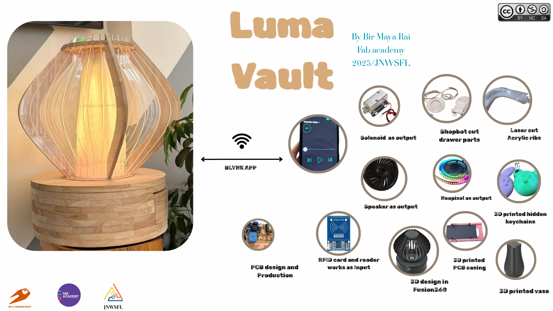
Luma Vault is a smart and secure locking system designed as a decorative lamp with hidden drawers, perfect for protecting personal or shared spaces. It uses an RFID authentication system to allow access only to authorized users—unlocking the drawer with a solenoid lock and lighting up a NeoPixel LED for visual confirmation. Powered by the compact Xiao ESP32-C3, Luma Vault also features Wi-Fi connectivity, enabling remote control and monitoring through the Blynk app.
🎵 RFID-Triggered Music Playback
Luma Vault also features RFID-based music control for a fun and interactive experience. Scanning a specific RFID tag starts music playback, while the Blynk app lets users control the next or previous track, and pause or stop the music remotely. This integration of RFID and app control adds a personal touch to the system, blending security with smart entertainment.
Final Summary Slide
Final Project Video
Youtube link for my final project
FFmpeg command I used to compressed my video:
ffmpeg -i presentation.mp4 -vcodec libx264 -crf 34 -preset veryslow -vf scale=-2:1080 -acodec libmp3lame -q:a 4 -ar 48000 -ac 2 presentationBir.mp4
BOM
| Components | Quantity | Unit Price (\$) | Total Price (\$) | Source |
|---|---|---|---|---|
| Rubber Wood | 1 | $10 | $10 | Local hardware store |
| Acrylic Sheet | 5 | $3.50 USD | $17.5 | jnwsfl |
| Seeed XIAO ESP32 C3 | 1 | $7.49 | $7.49 | jnwsfl |
| RFID Card and Reader | 2 | $6 | $6 | jnwsfl |
| Solenoid | 1 | $6 | $6 | jnwsfl |
| Relay Module (Single Channel) | 1 | $2.50 | $2.50 | jnwsfl |
| Buck Converter | 1 | $1.60 | $1.60 | jnwsfl |
| Mini DF player | 1 | $4.99 | $4.99 | jnwsfl |
| Speaker | 1 | $4.4 | $4.4 | jnwsfl |
| NeoPixels (1 Strip) | 1 strip | $0.18 | Amazon | |
| Diode (1N4007) | 1 | $0.24 | $0.24 | jnwsfl |
| Resistor (330Ω/1kΩ/0) | 4 / 2 /2 | $0.05 | $0.25 | jnwsfl |
| LEDs | 3 | $0.0035 | $0.0105 | jnwsfl |
| Male Pins header | 7pins | $0.10 | – | jnwsfl |
| Screw Pin header (2pin/3pin) | 2/1 | $0.10 | – | jnwsfl |
| 12V USB Adapter | 1 | $2.23 | $2.23 | jnwsfl |
| 3D Print (PLA) | 1 | $2.10 | $2.10 | jnwsfl |
| Vinyl | 1 | $2.10 | $2.10 | jnwsfl |
| Screws | APR | $2.10 | $2.10 | jnwsfl |
Rate in USD ($)$69.51 USD
Nu.5,769.37 (USD to BTN Rate as per 23.05.2025)
Design and Fabrication
The top layer I am going to placed rfid and used the acyrlic cut parts and wood layers

Second layers us where my electronics and drawers will be placed

For the neopixel casing, I design a vase in fusion which will also be additive for my final project
![]()
Here is the final version of my CAD design

Here is my integration for the bottom part

The top part where I am going to placed the lamp

This is how my whole system look after the integration

Electronics design and Production
For my final Project I am using the XIAO ESP32 C3 as the micro controlller
for my input devices I have: 3.3V RFID reader and cards
for my output devices I have 12V Solenoids with 0.2mA, 5V 15 Neo-Pixles and 5V DF mini player for audio output
I will use a buck convertor for 12 volts to 5 volts drop as regulator could not handle 7 volts drop. Given Below is how I have planned to give power supply for the solenoid, neopixel and RFID.
Power Management

Given below is circuit connection for my final board
System Design

For my final board design, I used KiCad to develop the PCB. This version integrates an XIAO-ESP32-C3 as the microcontroller unit (MCU), along with various breakout pins. Below is the final PCB schematic from KiCad:

Here’s the final PCB layout in KiCad and finalboard:

Here is my final pcb board. I used screw terminals on the back side of the PCB for output connections, which provides both a secure attachment and a cleaner board appearance.

I also design the casing for the pcb which will be the additive in my final project and attached the pcb on it.For the PCB casing, I designed a slider-style enclosure to make it easier to mount on the drawer. This design also allows convenient access for wiring and testing whenever needed.

Programming
Here is the flow chart of how my system is going to work.

In the inputand output , I programmed the input and output devices that I am going to use for my final project.
Testing RFID with Neopixels and solenoid
Before designing my pcb, I tested my code on breadboard using the ESP32C3 before redesigning my final Board.You can also check the links to Input and OutPut Week and Networking week for all indivividual coding I did.
I also tested the solenoid+rfid+neopixels
To ensure uninterrupted access for authorized users—even in the absence of an RFID card—the solenoid lock was successfully integrated with and controlled remotely through the Blynk IoT platform. Given below is the video how I implemented the blynk app.
Final Code
I tested the programming with the board that I fabricated and the code works.
    #include <SPI.h>
    #include <MFRC522.h>
    #include <Adafruit_NeoPixel.h>
    #define BLYNK_PRINT Serial

   #include <DFRobotDFPlayerMini.h>
   #include <SoftwareSerial.h>

   // Initialize software serial on pins D3 (RX) and D4 (TX)
   SoftwareSerial mySerial(D4, D3);

    // Create DFPlayer object
    DFRobotDFPlayerMini myDFPlayer;


   // Blynk credentials
   #define BLYNK_TEMPLATE_ID "TMPL390VtiLXt"
   #define BLYNK_TEMPLATE_NAME "Relay IOT"
   #define BLYNK_AUTH_TOKEN "AXrEK2JeuEziwFHw4ZFahgrJJkdrlXSE"

    #include <WiFi.h>
   #include <WiFiClient.h>
   #include <BlynkSimpleEsp32.h>

   // WiFi credentials
   char ssid[] = "Fablab";
   char pass[] = "#JSW@2o25";

    #define PIN D2          // Pin where NeoPixel is connected
    #define NUMPIXELS 30    // Change this to match your strip length

   Adafruit_NeoPixel pixels(NUMPIXELS, PIN, NEO_GRB + NEO_KHZ800);

    constexpr uint8_t RST_PIN = D0;
    constexpr uint8_t SS_PIN = D7;
    const int relayPin = D1;
    const int switchPin = D6;
   int switchState;

   MFRC522 rfid(SS_PIN, RST_PIN);
   MFRC522::MIFARE_Key key;

   byte nuidPICC[4];

    // Authorized card UIDs
   byte authorizedUID1[4] = {0xCC, 0x82, 0x36, 0x4A};
   byte authorizedUID2[4] = {0xFC, 0x4D, 0x11, 0x4A};

   bool relay_Flag = true;
    bool audio_Flag = true;
    bool blynkTriggered = false;

   //---------------------------- neo pixel variables
   unsigned long lastActionTime = 0;
     unsigned long rainbowInterval = 5000; // 5 seconds
   bool overrideColor = false;
   //-------------------------------------------------

   int value;

    BLYNK_WRITE(V0) {
    value = param.asInt(); // Get value from Blynk app

   if(value == 1){
   Serial.println("Opening door...");
    myDFPlayer.play(1);  // Play track 0001.mp3
   showRhombusPattern(pixels.Color(0, 255, 0)); // Green for authorized
    delay(500);
    digitalWrite(relayPin, value);
   }

    else {
   Serial.println("Closing door...");
   myDFPlayer.play(2);  // Play track 0001.mp3
   digitalWrite(relayPin, value);
   }
    delay(5000);
    }

   void setup() {
   pinMode(switchPin, INPUT_PULLUP);
   switchState = 1;

    Serial.begin(115200);
   mySerial.begin(9600);  // Start software serial for DFPlayer
    Serial.println(F("Initializing DFPlayer..."));
   // Initialize DFPlayer
    if (!myDFPlayer.begin(mySerial)) {
    Serial.println(F("DFPlayer initialization failed!"));
   Serial.println(F("1. Check RX/TX connections (must be crossed)"));
   Serial.println(F("2. Insert SD card with MP3 files"));
   while(true);  // Halt if initialization fails
   }

   Serial.println(F("DFPlayer Mini ready!"));
   myDFPlayer.volume(30);  // Set volume (0-30)

    // while (!Serial);
   Serial.flush();
   delay(1000);
   Serial.println("Starting RC522...");

   pinMode(relayPin, OUTPUT);
   digitalWrite(relayPin, LOW); // Ensure relay is off initially

   SPI.begin();
   rfid.PCD_Init();

   for (byte i = 0; i < 6; i++) {
   key.keyByte[i] = 0xFF;
   }

   Serial.println(F("Ready to scan cards Bir, Here! ..."));

   pixels.begin();
   pixels.show(); // Turn off all pixels

   // Connect to Blynk
    Blynk.begin(BLYNK_AUTH_TOKEN, ssid, pass);

   }

   bool compareUID(byte *uid, byte *authorizedUID) {
   for (int i = 0; i < 4; i++) {
    if (uid[i] != authorizedUID[i]) {
     return false;
   }
   }
    return true;
   }

   void loop() {
   Serial.println("IN");

   Blynk.run();

   switchState = digitalRead(switchPin);

   //neopixel startup
   if (millis() - lastActionTime > rainbowInterval && !overrideColor) {
   // showRhombusPattern(pixels.Color(255, 255, 255)); // white for ideal state
    showRhombusPattern(pixels.Color(255, 215, 0)); //

   lastActionTime = millis();
   }

   // Reset override after showing status for a short while
    if (overrideColor && millis() - lastActionTime > 3000) {
    overrideColor = false;
    lastActionTime = millis();
   }

   // Check for RFID card
   if (!rfid.PICC_IsNewCardPresent() || !rfid.PICC_ReadCardSerial()) return;

   byte *uid = rfid.uid.uidByte;

   if (compareUID(uid, authorizedUID1)) {
    Serial.println("Card 1 detected - Controlling relay");

    if (relay_Flag) {
    Serial.println("Opening door...");
   showRhombusPattern(pixels.Color(0, 255, 0));
   digitalWrite(relayPin, HIGH);
    } else {
    Serial.println("Closing door...");
    digitalWrite(relayPin, LOW);
   }

   relay_Flag = !relay_Flag;
    delay(5000); // Optional hold time

   } else if (compareUID(uid, authorizedUID2)) {
   Serial.println("Card 2 detected - Playing audio");

   if (audio_Flag) {
   Serial.println("Playing Audio!");
   myDFPlayer.play(6);
   // showRhombusPattern(pixels.Color(0, 255, 0));

   } else {
    Serial.println("Stopped Playing Audio!");
     myDFPlayer.stop();
    delay(1000);
   }

   audio_Flag = !audio_Flag;

   showRhombusPattern(pixels.Color(0, 0, 255)); // Blue for audio card
   } else {
   Serial.println("Unauthorized card.");
   myDFPlayer.play(3); // Play unauthorized sound
   showRhombusPattern(pixels.Color(255, 0, 0)); // Red for unauthorized
   }

   // Reset RFID reader
   rfid.PICC_HaltA();
    rfid.PCD_StopCrypto1();
   rfid.PCD_Init();
   delay(100);
   }


     // Show rhombus pattern (assuming 4 LEDs in a square configuration)
   void showRhombusPattern(uint32_t color) {
   // Sequence for rhombus pattern: 0, 1, 3, 2 (assuming physical layout)
    int rhombusSequence[30] = {0, 1, 2, 3, 4, 5, 6, 7, 8, 9, 10, 11, 12, 13, 14, 15, 16, 17, 18, 19, 20, 21, 22, 23, 24, 25, 26, 27, 28, 29};

   // First turn all LEDs off
   pixels.clear();

   // Light up LEDs in rhombus pattern
   for (int i = 0; i < NUMPIXELS; i++) {
   pixels.setPixelColor(rhombusSequence[i], color);
   pixels.show();
   delay(100); // Small delay for visible sequence
   }

  // Keep all rhombus LEDs on for a moment
   delay(500);
  }

  bool isAuthorized(byte *uid) {
  return compareUID(uid, authorizedUID1) || compareUID(uid, authorizedUID2);
}

 void printHex(byte *buffer, byte bufferSize) {
  for (byte i = 0; i < bufferSize; i++) {
  Serial.print(buffer[i] < 0x10 ? " 0" : " ");
  Serial.print(buffer[i], HEX);
  }
 }


  void showColor(uint32_t color) {
 for (int i = 0; i < NUMPIXELS; i++) {
  pixels.setPixelColor(i, color);
 }
 pixels.show();
 }

  void showRainbowPattern() {
 for (int j = 0; j < 256; j++) {
  for (int i = 0; i < NUMPIXELS; i++) {
  pixels.setPixelColor(i, Wheel((i * 256 / NUMPIXELS + j) & 255));
  }
   pixels.show();
   delay(10); // Small delay for visible rainbow motion
  }
   }

 uint32_t Wheel(byte WheelPos) {
 WheelPos = 255 - WheelPos;
  if (WheelPos < 85) {
  return pixels.Color(255 - WheelPos * 3, 0, WheelPos * 3);
  }
  if (WheelPos < 170) {
  WheelPos -= 85;
   return pixels.Color(0, WheelPos * 3, 255 - WheelPos * 3);
 }
 WheelPos -= 170;
  return pixels.Color(WheelPos * 3, 255 - WheelPos * 3, 0);
 }
System Integration
Here is the link to my system Integration
This is how I have attached the neopixel and rfid wiring
![]()
Here is how I have the wired the connection


Then I attached the PCB on the drawers

This is the final look of my guardian glow.

Answer and Planning
Here is the link to the week 17 Assignment
CC license
Creators can use a Creative Commons license to let others share and use their work. There are different types of licenses, each with its own rules.
I chose the Attribution-NonCommercial-ShareAlike license for my project. This means others can use, share, and change my work, but they must give me credit, not use it for commercial purposes, and share any changes under the same license.


Here is the Legal Code of CC BY-NC-SA
Here is the link where I have explanied about dissemination plan of my final project