Fab Academy Logo
EN | PT
EN | PT

Machine Design

FabAcademy 2025 Assignment

Cat-Themed Polargraph Plotter

The Cat Communication Robot

Our project combines mechanical design with robotics to create a unique drawing machine: a cat-themed polargraph plotter designed as a medium for "cat-to-human communication". This playful concept imagines a machine that could "translate" a cat's meows into written messages for their human companions.

Concept Evolution

Initially, we planned to participate in Flamingalo, the Portuguese version of Burning Man, with an art installation featuring a cable robot traveling between trees. However, due to circumstances, we redirected our efforts to align with our final project: the Cat's Gym.

Original Cable Robot Concept

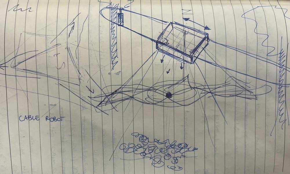
Original sketch of the cable robot concept

Mechanical Design

Polargraph Plotter with a Feline Twist

Our design is inspired by a traditional polargraph plotter, which uses two motors mounted at the top corners of a surface. These motors control the length of two cords or belts, which suspend a pen in between them. By precisely changing the lengths of these cords, the pen moves smoothly across a 2D surface, plotting images or text.

We adapted this basic idea with custom cat-themed mechanical features:

  1. Cat-Shaped Frame: The frame and gondola are designed with cat-inspired aesthetics, featuring cat-ear shapes and whisker-like elements.
  2. Pen Holder with Rack and Pinion System: A custom pen holder featuring a rack and pinion system controlled by a servo motor, allowing the pen to be lifted and lowered precisely. This is essential for drawing clean lines and separating strokes.
  3. Whisker-Inspired Sliding Mechanism: Sliding counterweights that mimic the shape and movement of cat whiskers, attached to a timing belt system, which adds visual charm and helps balance the pen holder's motion.
  4. Paper Roll Holder: In the back of the structure, there's a space designed to hold a roll of paper for continuous drawing.
Pen Holder CAD Model

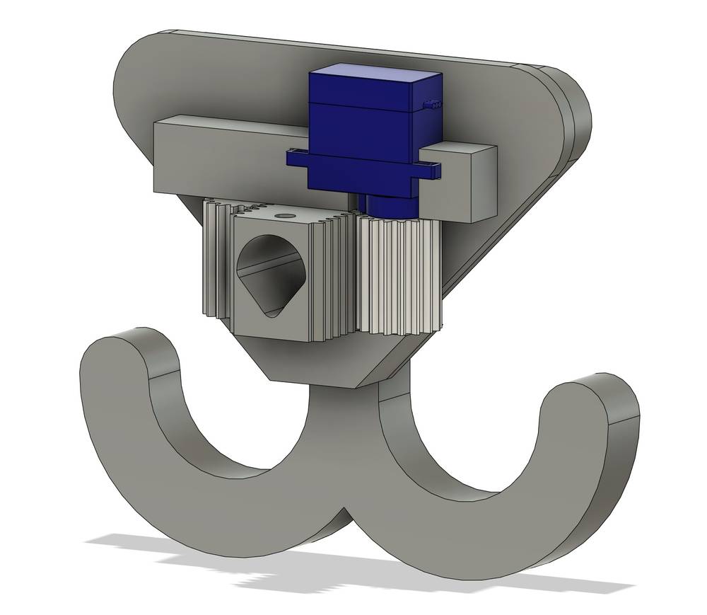
CAD model of the pen holder with rack and pinion system

Cat-Shaped Cut Parts

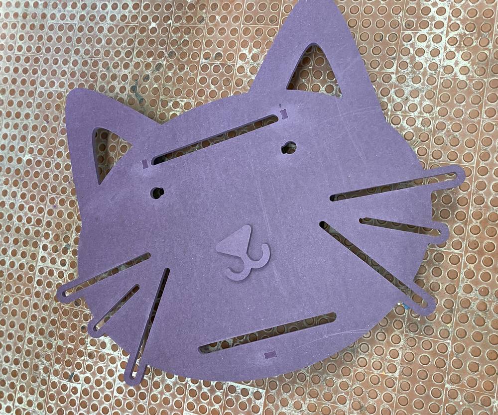
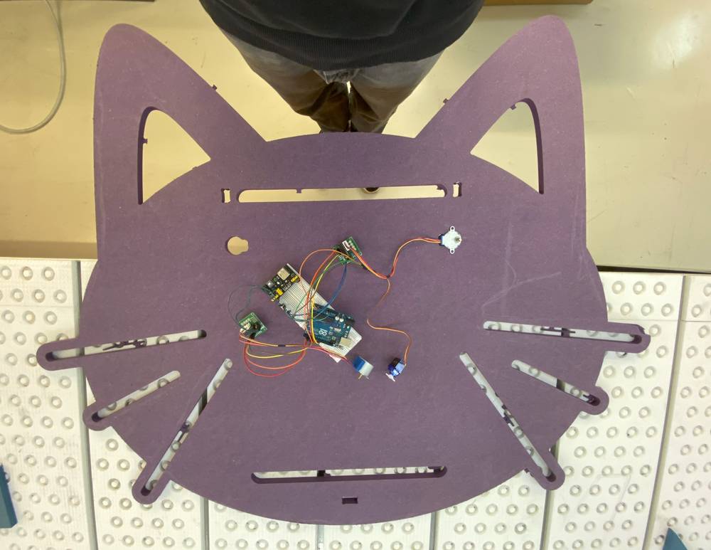
Cat-shaped laser-cut components

Hardware Setup

Required Components

  • Arduino Uno R3
  • 2× 28BYJ-48 Stepper Motors
  • 2× ULN2003 Driver Boards
  • 1× Small Servo Motor (SG90 or similar)
  • Power Supply (5-12V DC, at least 1A)
  • Jump Wires
  • Drawing Surface
  • Gondola (pen holder)
  • Dented Belts (for transmission)
  • Counterweights
  • Rack and Pinion System (for pen up/down movement)
Electronics Setup 1

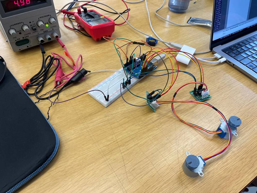
Testing electronics setup

Electronics Setup 2

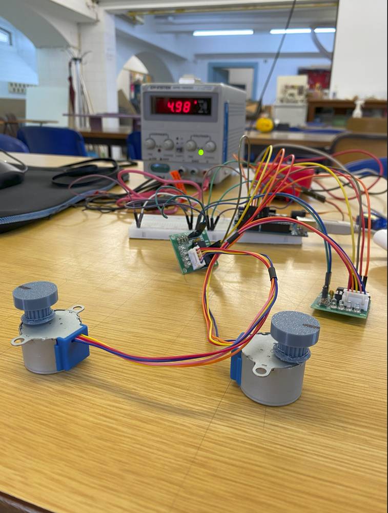
Wiring the components

Transmission System

Unlike traditional polargraph designs that use fishing line or string, our system uses dented belts for transmitting movement from the stepper motors to the gondola. This provides more precision and reliability. The counterweights on one side balance with the gondola weight, ensuring smooth movement. The servo motor connects to a rack and pinion system that precisely controls the pen's up/down movement.

Wiring Diagram

Arduino to Stepper Motor Connections

  • Left Stepper (ULN2003 Driver Board)
    • IN1 → Arduino Pin 8
    • IN2 → Arduino Pin 9
    • IN3 → Arduino Pin 10
    • IN4 → Arduino Pin 11
    • VCC → 5V (external power supply)
    • GND → GND (common ground with Arduino)
  • Right Stepper (ULN2003 Driver Board)
    • IN1 → Arduino Pin 4
    • IN2 → Arduino Pin 5
    • IN3 → Arduino Pin 6
    • IN4 → Arduino Pin 7
    • VCC → 5V (external power supply)
    • GND → GND (common ground with Arduino)
  • Servo Connections
    • Signal → Arduino Pin 12
    • VCC → 5V (external power supply)
    • GND → GND (common ground with Arduino)

Power Supply Connections

  • Connect the external lab power supply to provide 5V to the stepper motor driver boards and servo
  • Ensure common ground between the power supply and Arduino
  • The 28BYJ-48 motors typically draw 150-200mA each at 5V
  • The servo may draw up to 500mA during operation

Connection Notes

  • Make sure the stepper motor wires are connected in the correct order to the ULN2003 driver boards
  • The common ground connection between Arduino and power supply is essential
  • When testing, secure all wires properly to prevent accidental disconnection
Full Electronics Setup

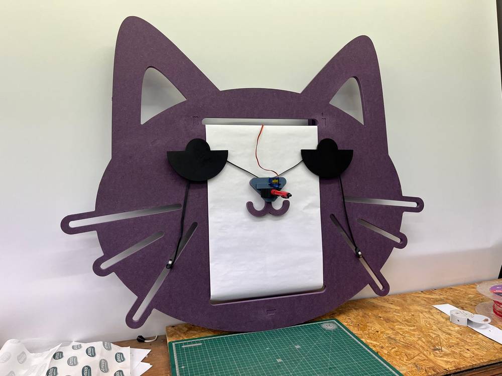
Complete electronics setup for the cat-themed polargraph

Test Software

Before implementing the full IPAD solution, we tested the hardware components individually. The following Arduino test sketch allowed us to verify the connections and proper functioning of both stepper motors and the servo:


// Polargraph Components Test Sketch
// Tests 28BYJ-48 stepper motors and servo on specified pins

#include <Stepper.h>
#include <Servo.h>

// Define stepper parameters
const int stepsPerRevolution = 2048;  // 28BYJ-48 steps per revolution with gear reduction
Servo penServo;

// Initialize left stepper on pins 8, 10, 9, 11 (this order is important for proper rotation)
Stepper leftStepper(stepsPerRevolution, 8, 10, 9, 11);

// Initialize right stepper on pins 4, 6, 5, 7 (this order is important for proper rotation)
Stepper rightStepper(stepsPerRevolution, 4, 6, 5, 7);

// Servo setup on pin 12
int servoPin = 12;
int penUp = 90;   // Adjust these angles based on your setup
int penDown = 140;

void setup() {
  // Set stepper motor speed (RPM)
  leftStepper.setSpeed(10);  // 10 RPM is a good starting speed for testing
  rightStepper.setSpeed(10);
  
  // Initialize servo
  penServo.attach(servoPin);
  penServo.write(penUp);  // Start with pen up
  
  // Initialize serial for debugging
  Serial.begin(9600);
  Serial.println("Polargraph Components Test");
  Serial.println("Commands: 'L' - Left stepper, 'R' - Right stepper, 'U' - Pen up, 'D' - Pen down, 'B' - Both steppers");
}

void loop() {
  // Check if there's any incoming serial data
  if (Serial.available() > 0) {
    char command = Serial.read();
    
    switch (command) {
      case 'L':
      case 'l':
        // Test the left stepper motor with 1/4 rotation in each direction
        Serial.println("Testing left stepper - 1/4 rotation clockwise");
        leftStepper.step(stepsPerRevolution / 4);  // 512 steps = 1/4 rotation
        delay(500);
        Serial.println("Testing left stepper - 1/4 rotation counter-clockwise");
        leftStepper.step(-stepsPerRevolution / 4);
        break;
      
      case 'R':
      case 'r':
        // Test the right stepper motor with 1/4 rotation in each direction
        Serial.println("Testing right stepper - 1/4 rotation clockwise");
        rightStepper.step(stepsPerRevolution / 4);
        delay(500);
        Serial.println("Testing right stepper - 1/4 rotation counter-clockwise");
        rightStepper.step(-stepsPerRevolution / 4);
        break;
      
      case 'U':
      case 'u':
        // Move the servo to pen-up position
        Serial.println("Pen up");
        penServo.write(penUp);  // 90 degrees by default
        break;
      
      case 'D':
      case 'd':
        // Move the servo to pen-down position
        Serial.println("Pen down");
        penServo.write(penDown);  // 140 degrees by default
        break;
      
      case 'B':
      case 'b':
        // Test both steppers simultaneously for coordinated movement
        Serial.println("Testing both steppers simultaneously");
        // Move both steppers forward simultaneously
        for (int i = 0; i < (stepsPerRevolution / 8); i++) {
          leftStepper.step(1);
          rightStepper.step(1);
        }
        delay(500);
        // Move both steppers backward simultaneously
        for (int i = 0; i < (stepsPerRevolution / 8); i++) {
          leftStepper.step(-1);
          rightStepper.
          rightStepper.step(-1);
        }
        break;
    }
  }
}
              

How to Use the Test Software

  1. Connect the Arduino to your computer via USB.
  2. Make sure all hardware connections match the wiring diagram.
  3. Open the Arduino IDE and upload the sketch.
  4. Open the Serial Monitor (Tools → Serial Monitor, set to 9600 baud).
  5. Send the following single-character commands to test each component:
    • `L` to test the left stepper motor (connected to pins 8,9,10,11)
    • `R` to test the right stepper motor (connected to pins 4,5,6,7)
    • `U` to move the servo to pen-up position
    • `D` to move the servo to pen-down position
    • `B` to test both stepper motors simultaneously

What to Look For During Testing

  • Stepper Motors: Should rotate smoothly without stuttering or skipping steps
  • Servo: Should move reliably between up and down positions
  • Power Supply: Should provide stable voltage and current during operation
  • Temperature: Components should not overheat during testing

IPAD Software Implementation

Installation Steps

  1. Download and install the Arduino IDE from arduino.cc
  2. Download and install Processing from processing.org
  3. Clone or download the IPAD repository from GitHub
  4. Install the required Arduino libraries:
    • AccelStepper (for improved stepper motor control)
    • Servo (for pen control)
  5. Open the IPAD_Firmware.ino file from the downloaded repository
  6. Modify the pin assignments in the code to match our specific setup:
    
    // Modify these lines to match your pin connections
    // Left stepper on pins 8,9,10,11
    #define LEFT_STEP_PIN1 8
    #define LEFT_STEP_PIN2 9
    #define LEFT_STEP_PIN3 10
    #define LEFT_STEP_PIN4 11
    
    // Right stepper on pins 4,5,6,7
    #define RIGHT_STEP_PIN1 4
    #define RIGHT_STEP_PIN2 5
    #define RIGHT_STEP_PIN3 6
    #define RIGHT_STEP_PIN4 7
    
    // Servo on pin 12
    #define SERVO_PIN 12
                    
  7. Upload the firmware to the Arduino
  8. Open Processing and load the IPAD_Controller.pde file
  9. Configure the settings to match our hardware setup:
    • Set the correct COM port
    • Configure machine width and height
    • Set motor specifications for the 28BYJ-48 steppers
  10. Run the Processing sketch to open the control interface

Key IPAD Configuration Settings

When working with the IPAD software, we paid special attention to:

  1. Machine Settings in Processing Controller
    • Set the correct COM port for the Arduino
    • Configure the machine width and height to match our physical setup
    • Set the motor steps per revolution (2048 for 28BYJ-48)
    • Adjust the microstepping settings if you modified the firmware
  2. Motor Settings
    • Set the correct motor speed (500-800 steps/min for the 28BYJ-48)
    • Set acceleration values (100-200 steps/sec² for 28BYJ-48)
    • If motors skip steps, reduce speed and increase power supply current
  3. Pen Settings
    • Configure servo up/down positions (typically between 70-150 degrees)
    • Set pen lift and lower delay (200-500ms recommended)
Pen Holder

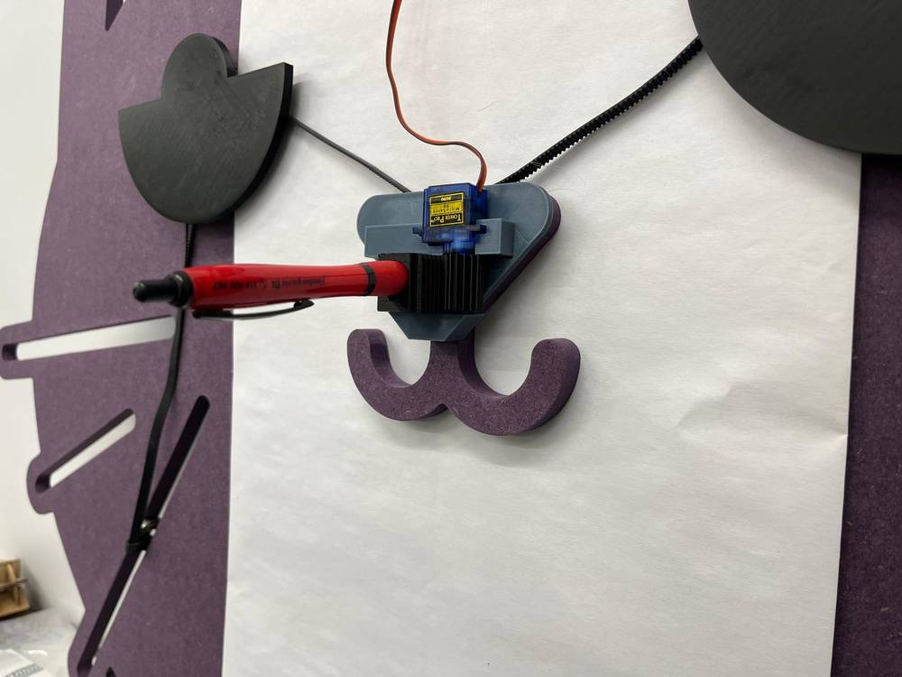
Close-up of the pen holder with the servo-controlled rack and pinion system

Final Assembly and Results

The final assembly brought together all components into our cat-themed design. The dented belts connect the stepper motors to the gondola with the cat-themed frame. The servo-controlled rack and pinion system provides precise pen control, while the counterweights ensure smooth motion across the drawing surface.

Our polargraph successfully draws various patterns and shapes, and with further development could be integrated into our broader Cat's Gym project. The cat-shaped aesthetic perfectly complements its intended purpose as a "feline secretary" that translates cat communications into visual form.

Future Improvements

  • Cat Vocalization Recognition: Implement actual sound recognition to detect and classify different cat meows and vocalizations.
  • Machine Learning Integration: Use machine learning to analyze cat behaviors and develop a more accurate "translation" system.
  • Better Belt Tensioning: Design an improved tensioning system for the dented belts to maintain consistent precision.
  • Wireless Control: Add Bluetooth or WiFi capability for remote control of the drawing system.
  • Battery Power: Implement a rechargeable battery system to make the device more portable.

Checklist

Group Assignment

  • ✅ Design a machine that includes mechanism + actuation + automation + application
  • ✅ Build the mechanical parts and operate it manually
  • ✅ Document the group project
  • ⬜ Actuate and automate your machine (in progress)

References and Resources

Note: This project combines mechanical design with electronics and programming to create a unique, cat-themed polargraph drawing machine. The design not only functions as a plotting device but also serves as an artistic expression of how technology might help bridge the communication gap between cats and their human companions.