09 - Input Devices
Group assignment
We were tasked with probing an input device(s)'s analog levels and digital signals, add a sensor to a microcontroller board that you have designed and read it wih debugging.
The oscilloscope provides clear imaging of what is going on helps with the debugging process. A link to the group assignment page is given below:
https://academany.fabcloud.io/fabacademy/2025/labs/barcelona/students/group-assignments/
Individual assignment:
- measure something: add a sensor to a microcontroller board that you have designed and read it
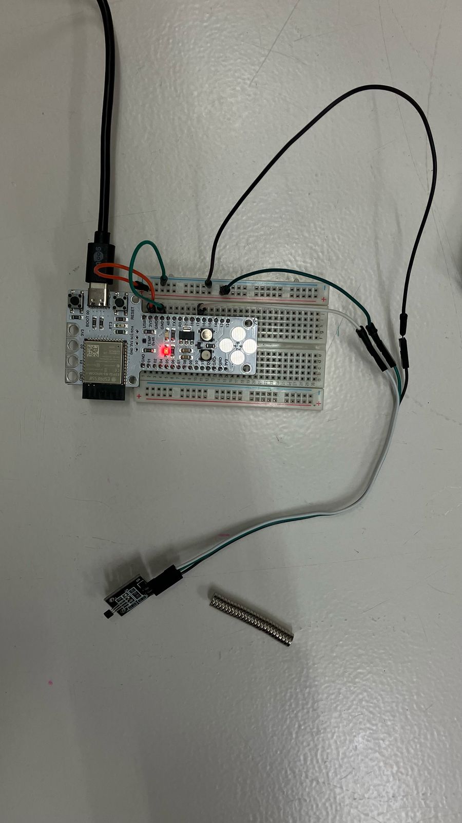
So, my board is currently being cut in our wonderful Roland machine so here are some playtime moments using the Barduino board the Barcelona lab has provided us with.
The input devises investigated on this page are:
Variable resistors / Potentiometer
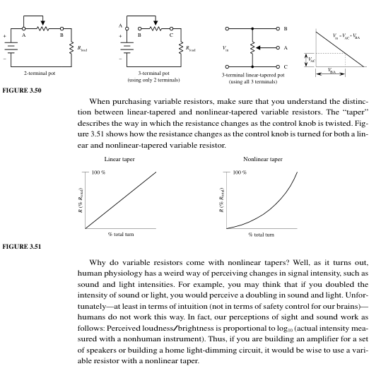
Variable resistors
We made a little circuit with a potentiometer and wrote some code to give us out a voltage reading.
void setup() {
  // put your setup code here, to run once:
  pinMode(17, INPUT);
  Serial.begin(115200);
}

void loop() {
  // put your main code here, to run repeatedly:
  int lecture = analogRead(17);
  Serial.println(lecture);
  delay(50);
}
The potentiometer works using a voltage divider, varying the resistance of a resistor in a resistor in series in order to change the output sent to the pin.
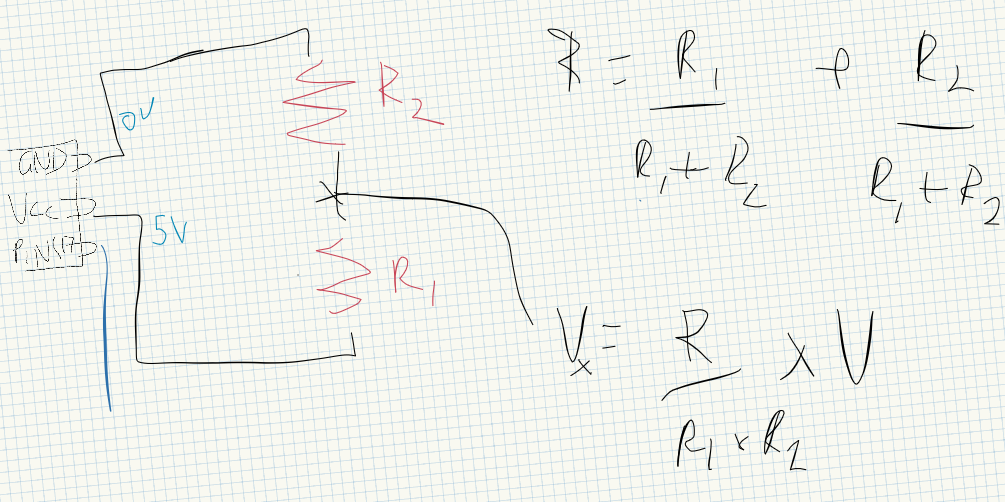
Playing around with the potentiometer and turning the knob gives us a variable volage output. 4095V associated with the 3.3V output from our barduino board.
KY035 Analog Hall Magnetic Sensor
We used the KY035 hall magnetic sensor to see how it is affected by a metal bolt.

https://arduinomodules.info/download/ky-035-analog-hall-magnetic-sensor-fritzing-part/
You can find the arduino code below followed with the variable voltage response as we move it closer and further away from the sensor.
int sensorPin = 17;   // interface pin with magnetic sensor
int val;              // variable to store read values

void setup() {
  pinMode(17, INPUT);   // set analog pin as input
  Serial.begin(115200);   // initialize serial interface
}

void loop() {
  val = analogRead(sensorPin);  // read sensor value
  Serial.println(val);          // print value to serial

  delay(100);
}
The standing voltage was half of 4095 value corresponding to 3.3V. The voltage drops or increases depending on the polarity.
KY027 magic light cup effect
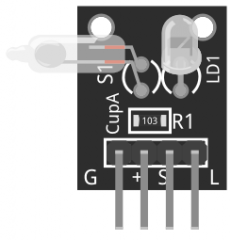
The following is copied from https://arduinomodules.info/ky-027-magic-light-cup-module/
Using PWM to drive the LEDs on each module, you can achieve the effect of light being “magically” transferred from one module to the other when tilting them, similar to pouring water from one cup to the other, hence the name.
In this Arduino sketch we’ll use both modules to create the magic light cup effect. The mercury switches in each module provide a digital signal that is used to regulate the brightness of the LEDs using using PWM.
Place the modules so the mercury switches on each other are facing in the opposite directions. Tilting the modules will decrease the brightness on one module while increasing it on the other one, creating the illusion of light magically passing from one module to the other.
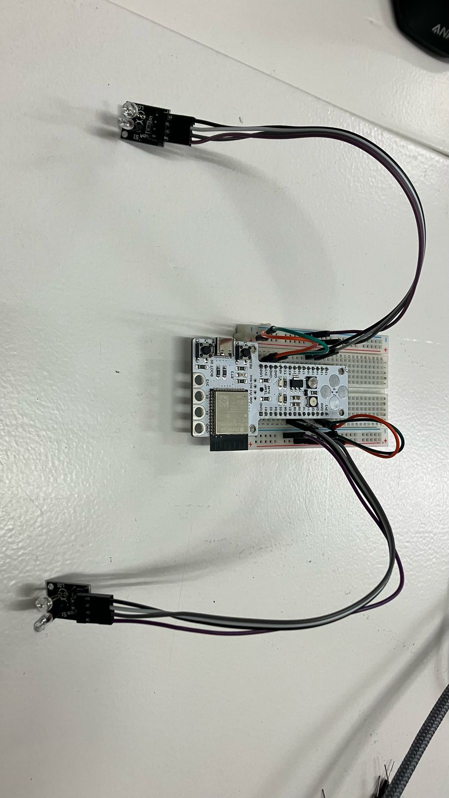
We set up our barduino with two KY027s on separate sides of a breadboard and modified the arduino code to correspond to our pins. The Arduino code is as follows:
int ledPinA = 15;
int switchPinA = 13;
int switchStateA = 0;
int ledPinB = 8;
int switchPinB = 10;
int switchStateB = 0;
int brightness   = 0;

void setup()
{
pinMode(ledPinA, OUTPUT);
pinMode(ledPinB, OUTPUT);

pinMode(switchPinA, INPUT);
pinMode(switchPinB, INPUT);
}

void loop()
{
switchStateA = digitalRead(switchPinA);
if (switchStateA == HIGH && brightness != 255)
{
brightness ++;
}
switchStateB = digitalRead(switchPinB);
if (switchStateB == HIGH && brightness != 0)
{
brightness --;
}
analogWrite(ledPinA, brightness);  //  A slow fade out
analogWrite(ledPinB, 255 - brightness);  // B slow bright up
delay(20);
}
You can see in the video below, how the light “transfers” from one bulb to another as one slowly fades out. This is of course only an illusion as it corresponds to the position of the mercury.
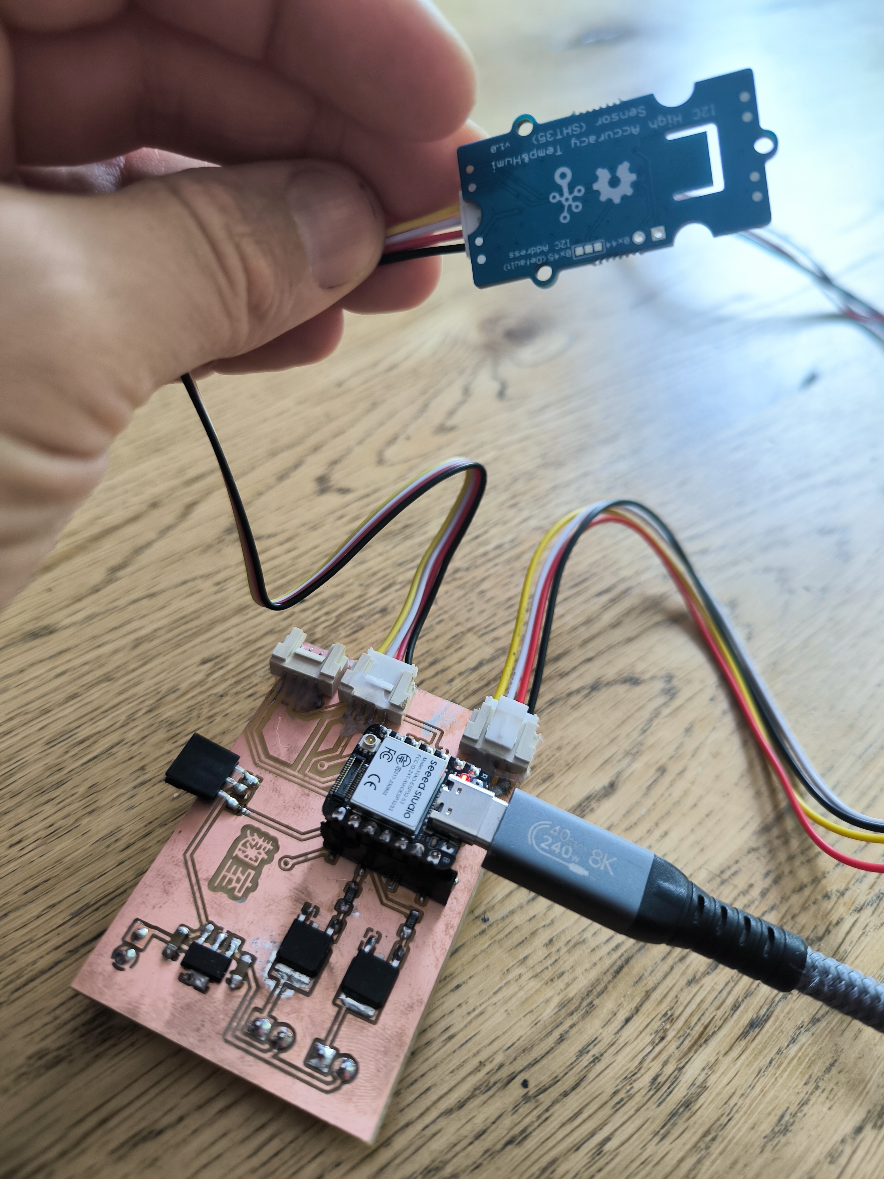
Experimenting with the SHT35 with my Koji Board v7
After multiple attempts at creating the Koji Board I finally have a board that is appropriate to use for testing different input and output devices.
Here we can see the board with a potentiometer and a SHT35 temperature and humidity senor connected to a Xiao ESP32S3 via grove connectors.
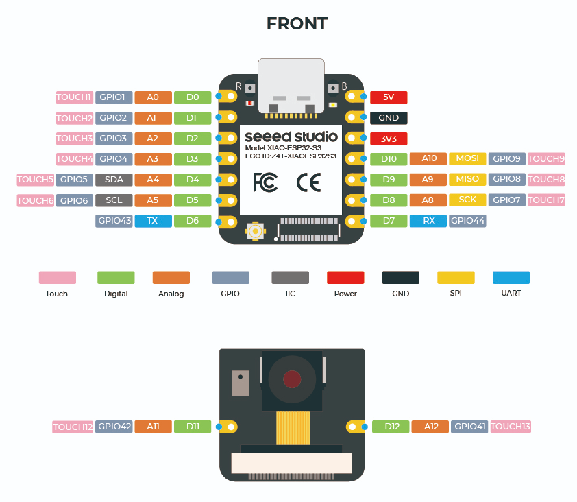
I then looked at the pin layout for the xiao in order to correctly code the sda and scl pins. All the information concerning the Xiao ESP32S3 can be found here, and the pin layout is given in the figure below.
Now that we know the SDA and SCL pins are D4 and D5 we can call the wire.h and Seed_SHT35.h libraries to write a code that reads the temperature from the sensor and prints the value in the serial monitor on Arduino IDE. The code is given hereafter:
// This code is for the Seeed Studio SHT35 Temperature Sensor

#include <Wire.h>
#include "Seeed_SHT35.h"

// Define the SDA and SCL pins for the Xiao ESP32S3
#define SDA_PIN D4
#define SCL_PIN D5

// Create an SHT35 object globally, passing the SCL pin
SHT35 sensor(SCL_PIN);

void setup() {
  Serial.begin(115200);
  delay(10);
  Serial.println("Seeed Studio SHT35 Temperature Sensor Test");

  // Initialize Wire library with custom SDA and SCL pins
  Wire.begin(SDA_PIN, SCL_PIN);

  if (sensor.init()) { // Use the init() function
    Serial.println("Couldn't find SHT35 sensor!");
  } else {
  Serial.println("Found SHT35 sensor!");
  }
  delay(1000);
}

void loop() {
  delay(2000);
  float temp, hum;

  if (NO_ERROR != sensor.read_meas_data_single_shot(HIGH_REP_WITH_STRCH, &temp, &hum)) {
    Serial.println("Failed to read temperature!");
  } else {
  Serial.print("Temperature: ");
  Serial.print(temp);
  Serial.println(" °C");
  delay(100);

  Serial.println(); // extra line for clarity
  delay(2000); // Read every 2 seconds
}}
In the video below you can see the temperature being printed in the serial monitor along with a message depending on the temperature, by adding an if loop to the code.
 // Temperature commentary
  if (temp < 20.0) {
    Serial.println("Oh my, it's a little nippy out there. Don't forget your sweater!");
  } else if (temp >= 20.0 && temp <= 25.0) {
    Serial.println("I could really get used to this, just the right temperature for comfortable work and living!");
  } else if (temp > 25.0) {
    Serial.println("Deary me, get the ice pops out!");
  }