07 : Computer Numeric Control Machining
Group Project
The group assignment this week was to characterise the design rules for different materials on the CNC machine we were using in the lab, the Raptor XSL 3200. More detail can be found here https://academany.fabcloud.io/fabacademy/2025/labs/barcelona/students/group-assignments/week7.html.
For this weeks work a standard cut seems sufficient as the wood we are using is quite soft and damages easily, we can just sand down the cut object.
Objective
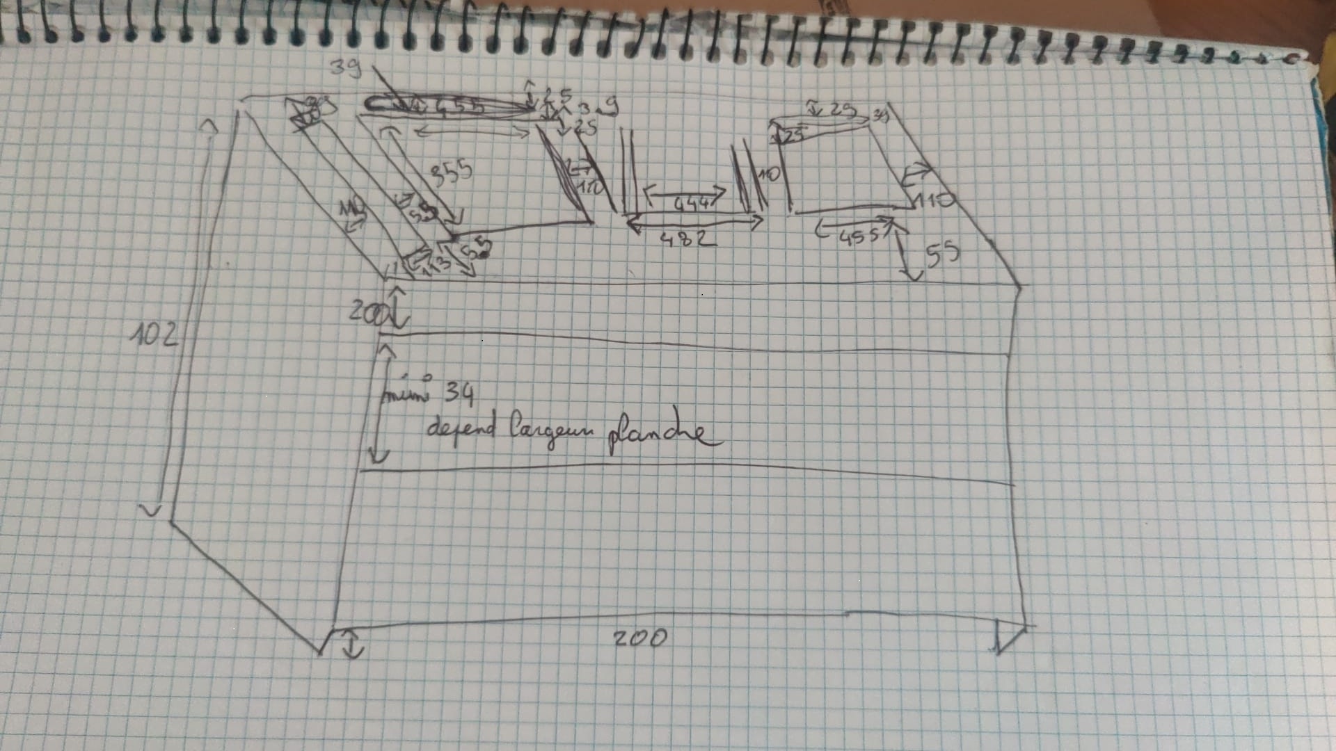
The objective of this week for me was to create a desk for two vinyl players and a mixer with space for records underneath. The client is a music producer friend of mine, who already has an idea of what he would like, here are the measurements:
Research:
Furniture in 24 hours : Spiras Zakas
https://archive.org/details/furniturein24hou0000zaka_v2s1
CAD design
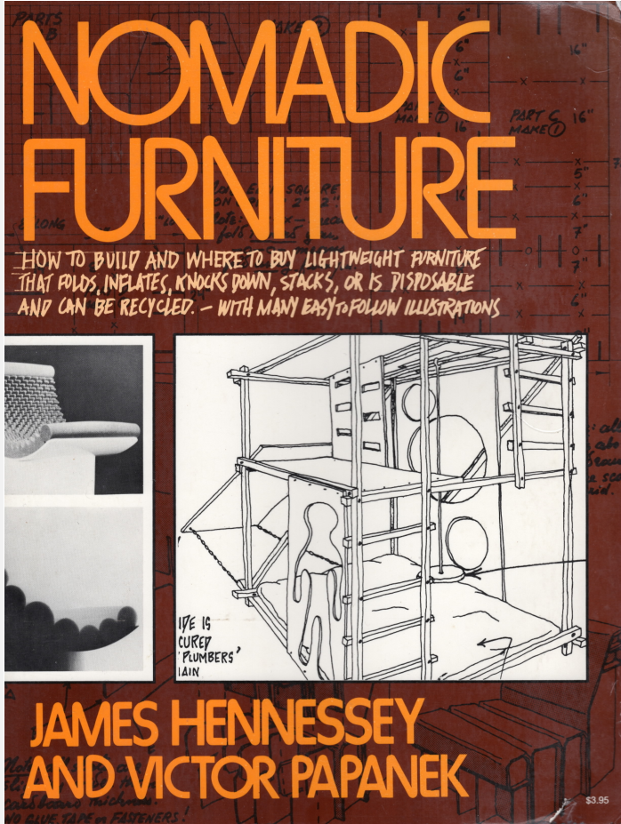
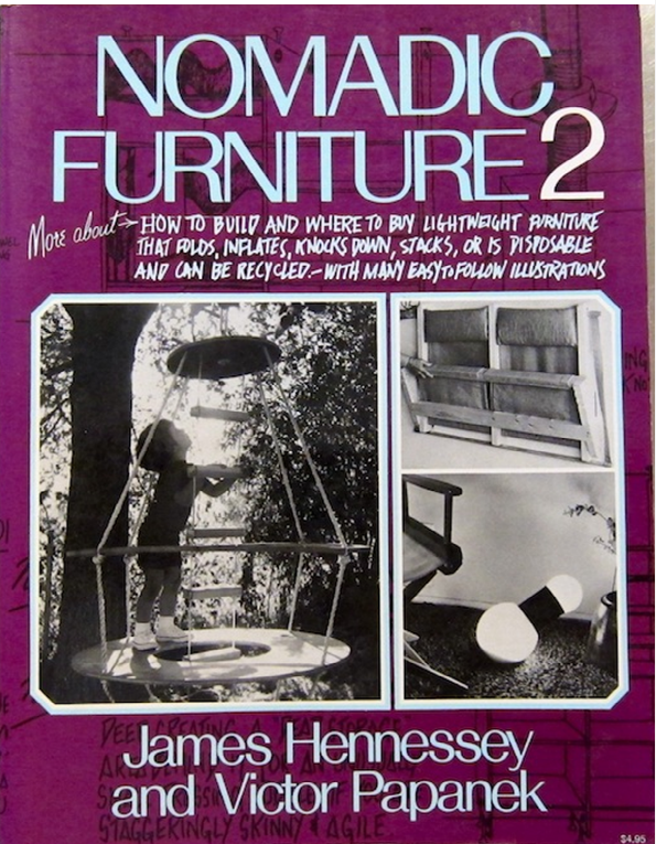
I decided to take inspiration from these books to create a modular design using different methods to assemble the CNC parts together:
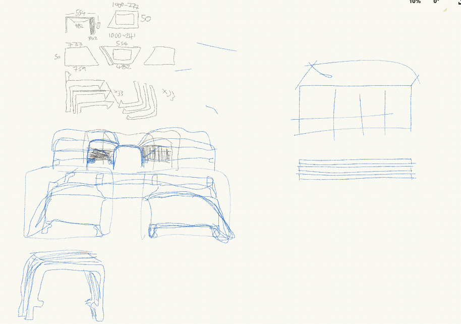
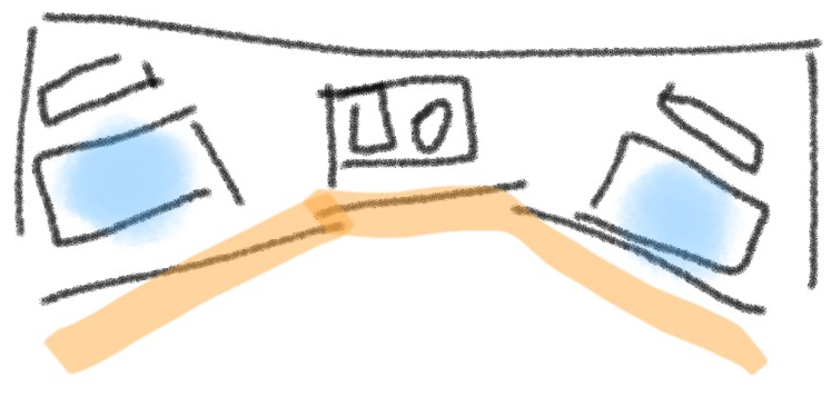
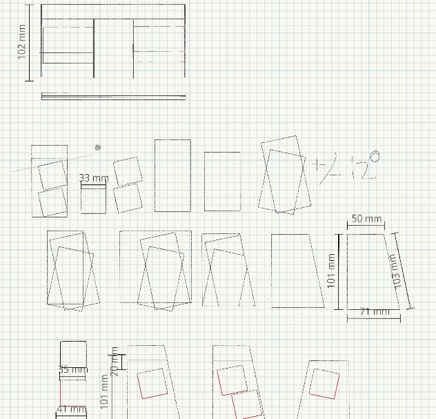
I toyed with the idea of increasing ergonomics and “playfulness” adding a 12 degree angle to create a more interesting look
I came back to the client with some concepts for the design, however they opted for a more classical boxy design. Time to move onto a solid 3D design in fusion 360.
We have two thicknesses of plywood boards to use in the lab, 10 and 15 mm, and I presume my final design I may have to use a 19mm for aesthetics for my final design. I chose to use parametric design to make it easier to tweak the design and use a press-fit structure for the desk.
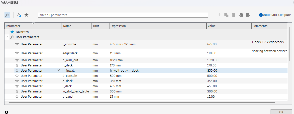
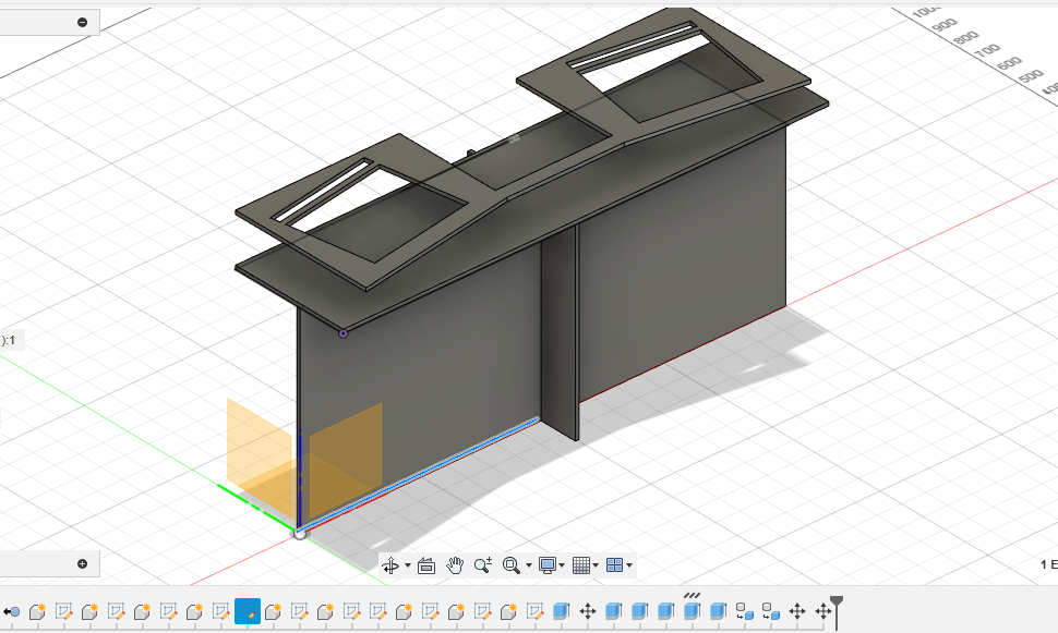
Each of the components shown in the arrangements below were drawn in 2D parametrically and extruded by the wood panel thickness.
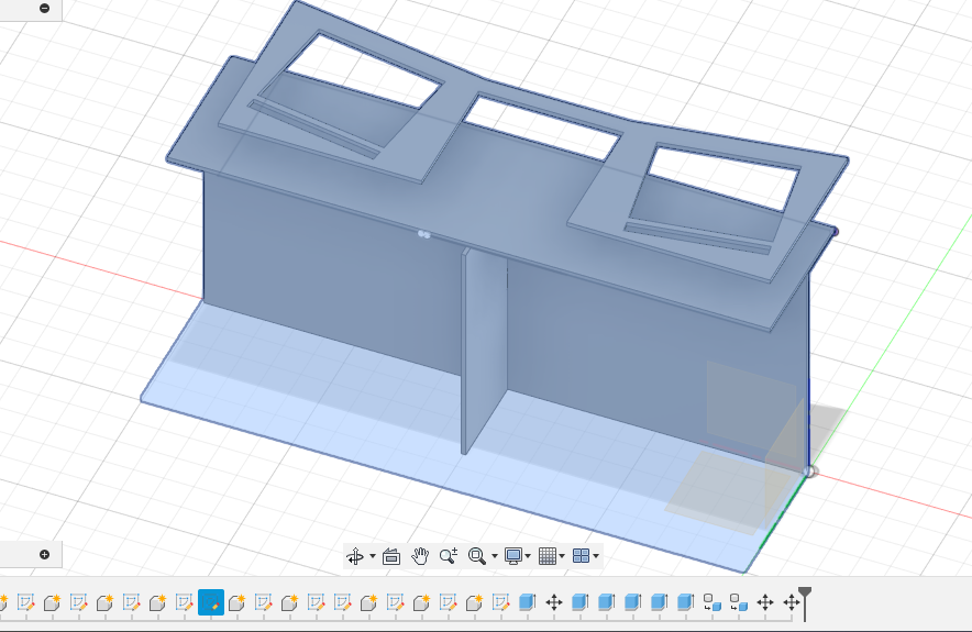
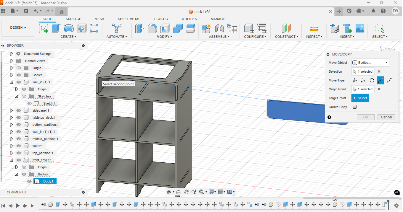
To assemble the parts into the 3D structure I select a component, click M for “move” and then select the point to point option. This works well for the press fit design because I can click on a point on the male part of one component and connect it to the female part of another.
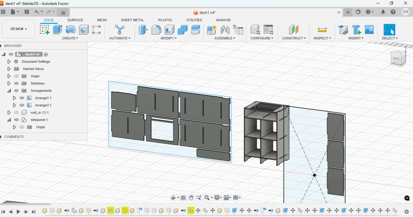
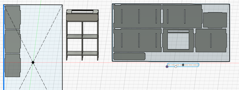
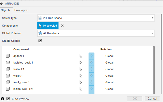
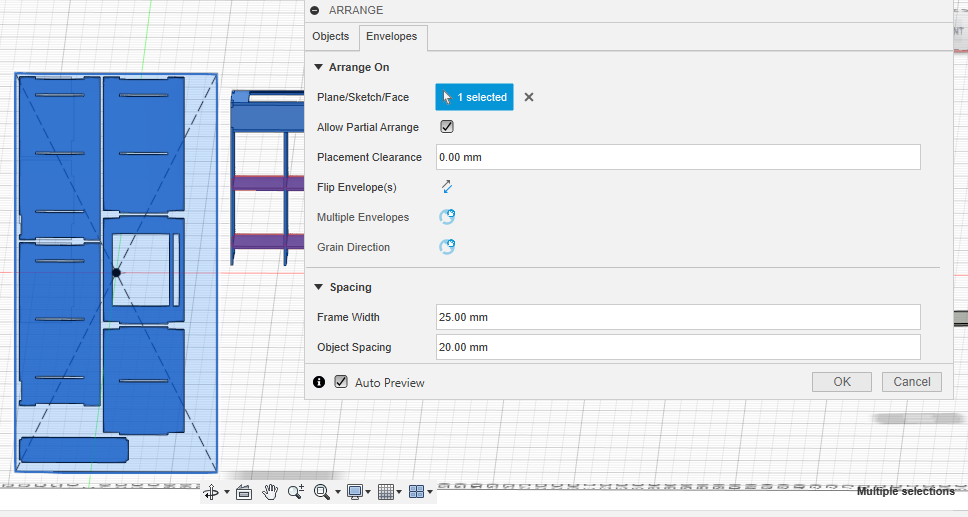
To prepare the pieces for the CNC machine I used the “Arrange” function, selecting all of the components and to be arranged and then the envelope for them to be arranged in. Three pieces are in excess so I’m going to be sneaky and negotiate some wood from my friends in the lab.
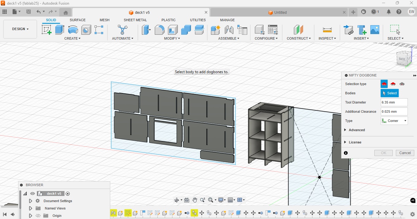
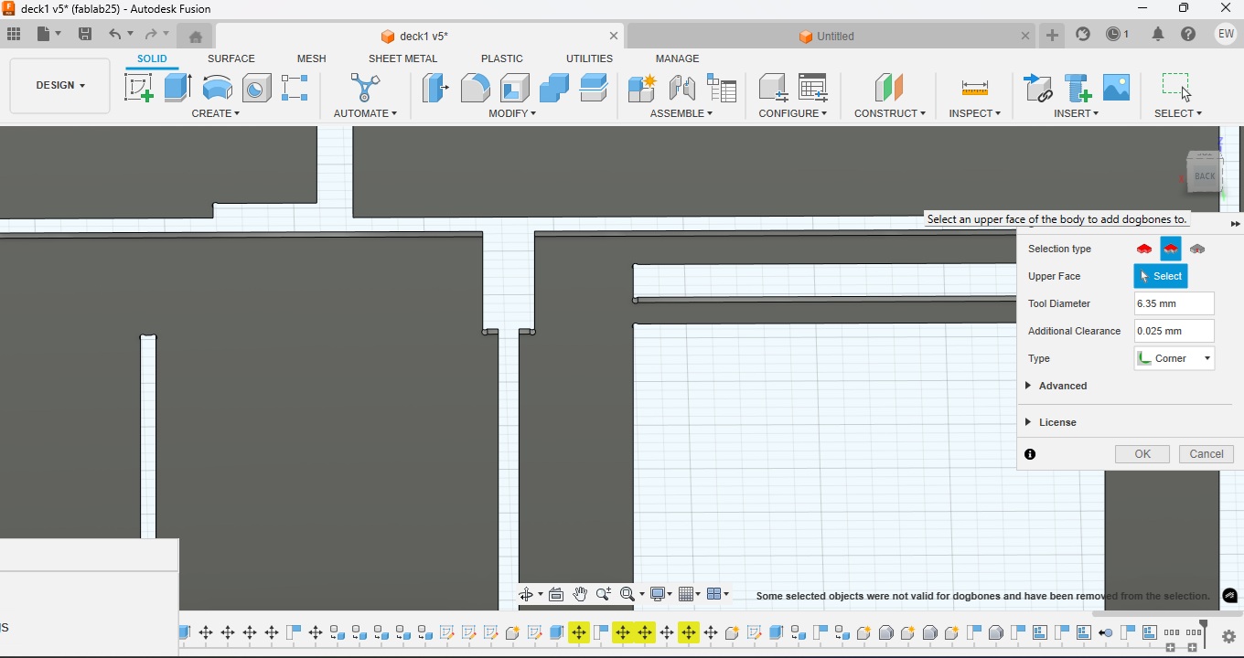
The final step before sending the cuts to the cutting software is to add dogbones to the corners so the amount of sanding required for the press-fits is kept at a minimum. The Autodesk Nifty dogbone extension allows the dogbones to be applied to the components directly in Fusion 360.
Rhino Cam : Preparing file for CNC milling
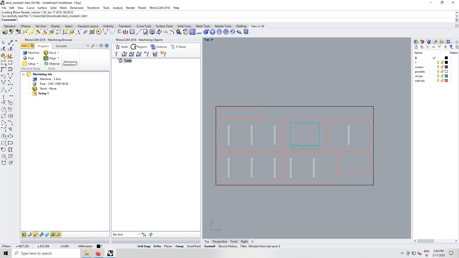
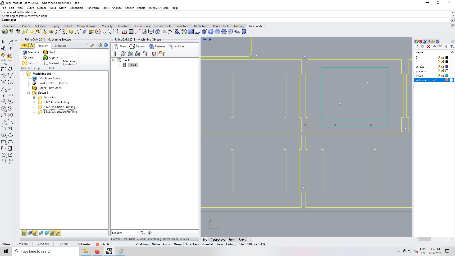
Here is the Rhino file design with the RhinoCAM settings.
The design has to be seperated into different layers corresponding to the cut sequence, as shown in the figure RC1 below:
- the screw holes will be placed first
- the press fit holes will be pocketed second
- the incuts,
- followed by the outlines profiles
The tool then has to be setup and the control geometry defined. For ease of use I place the origin at the bottom left corner of the cut. I defined the speed and tool characteristics before moving onto the machining jobs.
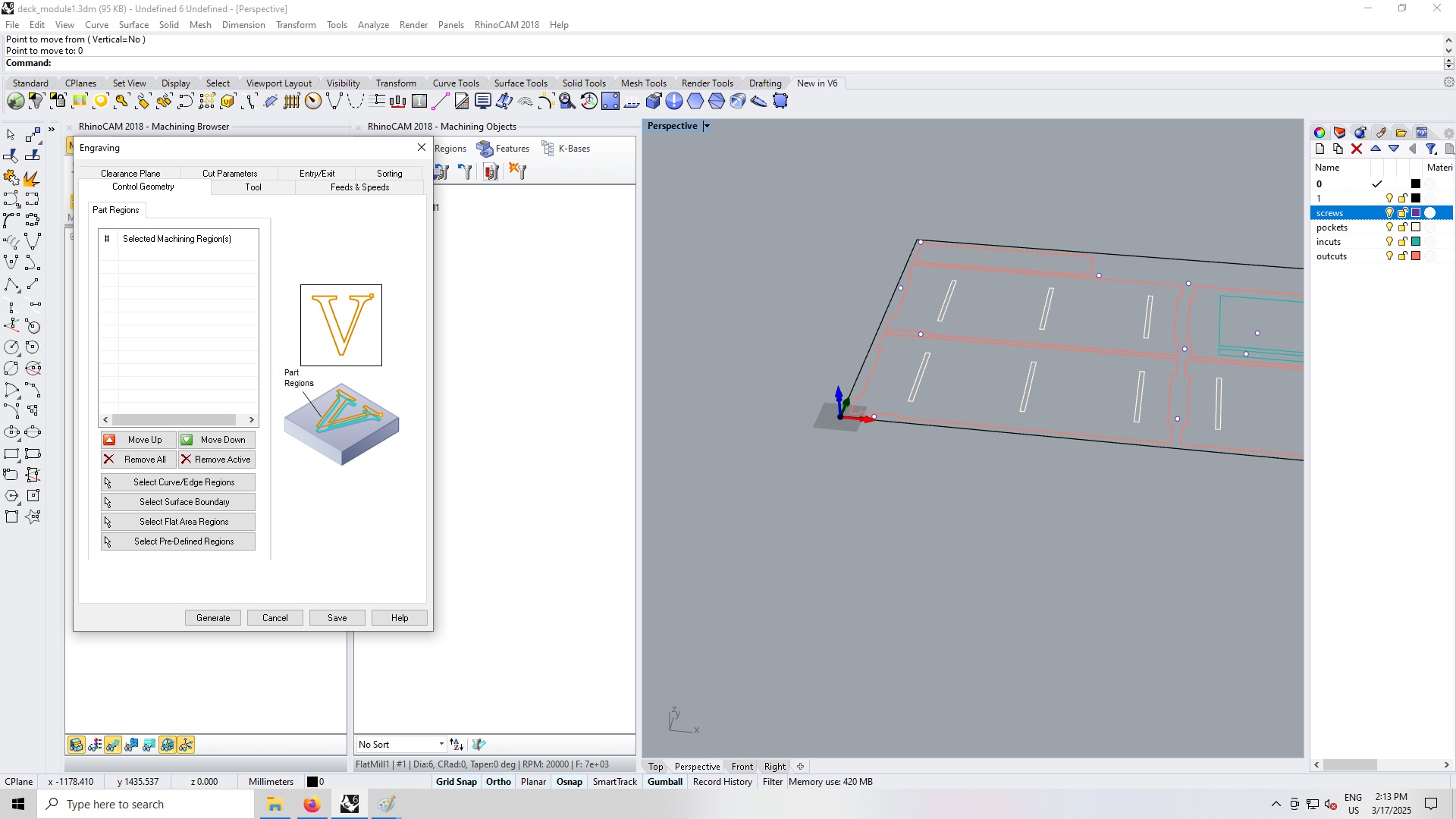
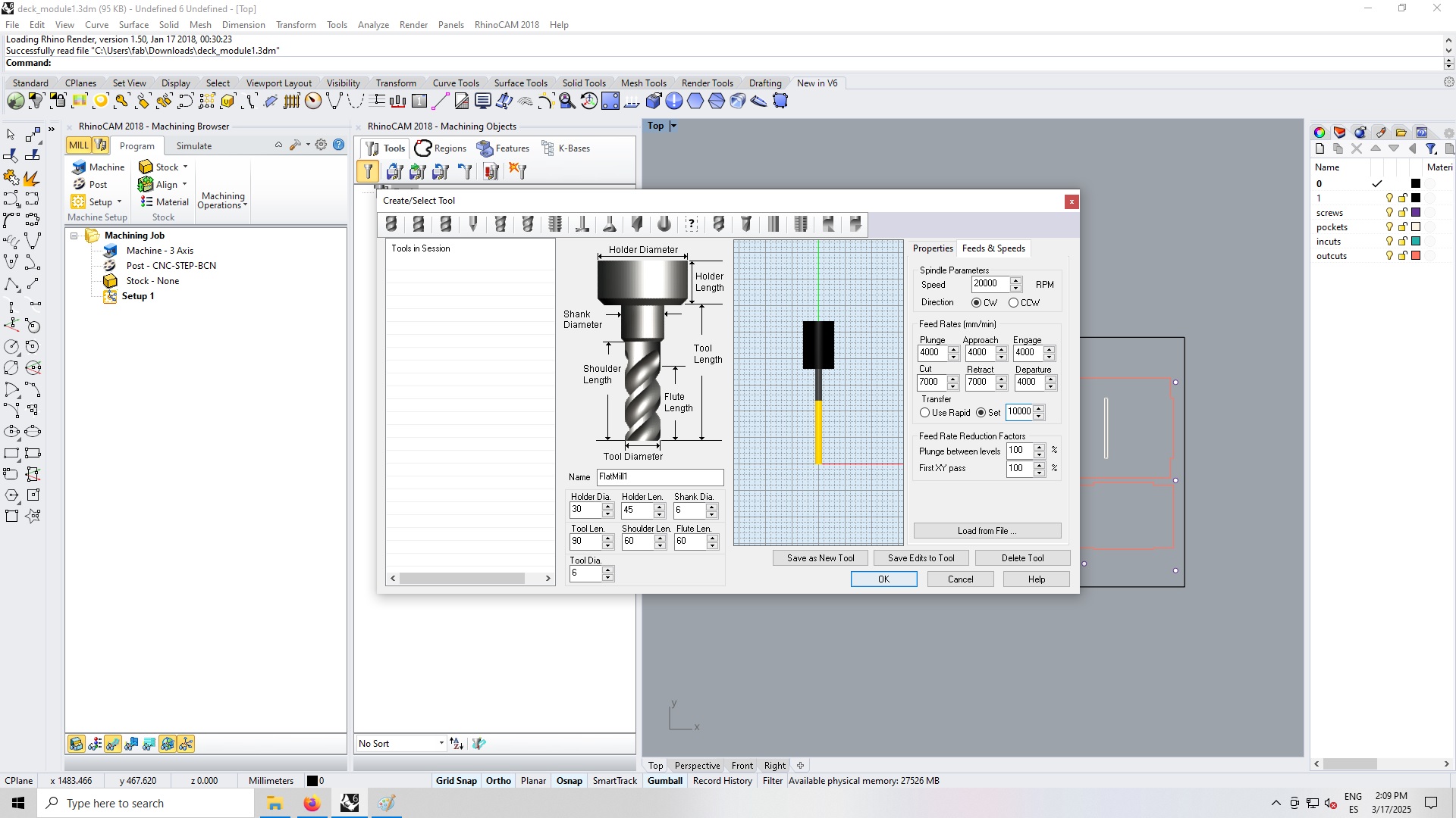
The screws placement holes are set up as an engraving job whilst the pocketing, incut and outcuts are cuts which will be cut in layers of 3.15mm. RhinoCam will then generate the G-Code for the machine. I made the mistake of not selecting the correct machine, so an error occurred when I tried to upload the design to the Raptor machine software.
I measured the plywood board I am using to get a more precise measurement. The thickness ranged from 14.6 to 14.8 mm, and the board dimensions were 1230 x 2500.
After feedback from my class mates, I decided to cut conventionally, not using the upcut. I also ensured that the machine would cut 15.5mm to be sure that the cuts went all of the way through.
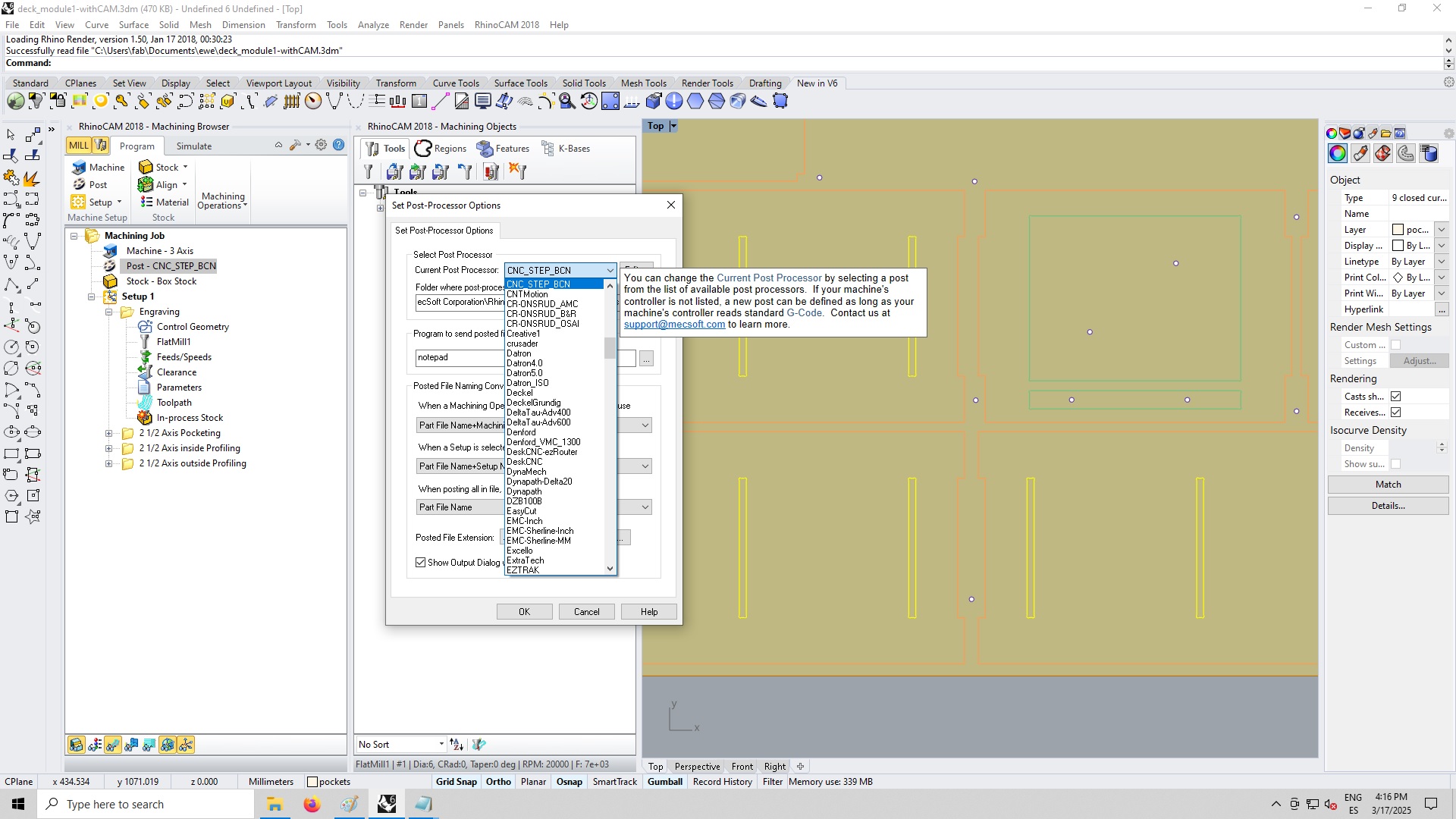
Here are the Gcode files:
Computer Controlled Machining
The GCode files are uploaded in the Raptor Machine app. I verified the speeds and the cutting tool before moving it to the far end of the machine with the machine controls.
By default the machine moves very slowly so it is important to click “Rapid” movement. When moving the tool in the Z axis it is good practice to use the remote and going slowly as to not break the end mill or the tool.
I placed the wood stock onto the machine platform and then zeroed the endmill to the bottom corner of the stock. I then launched the first job which engraves small holes where the screws are to be placed.
I screwed in the screws, making sure to go back and forth with the screwdriver to ensure that the board is as flat as possible for the milling.
Once the woodstock was secured, I re-zeroed the Z and launched the rest of the cut. You can see in the video below the machine in action.
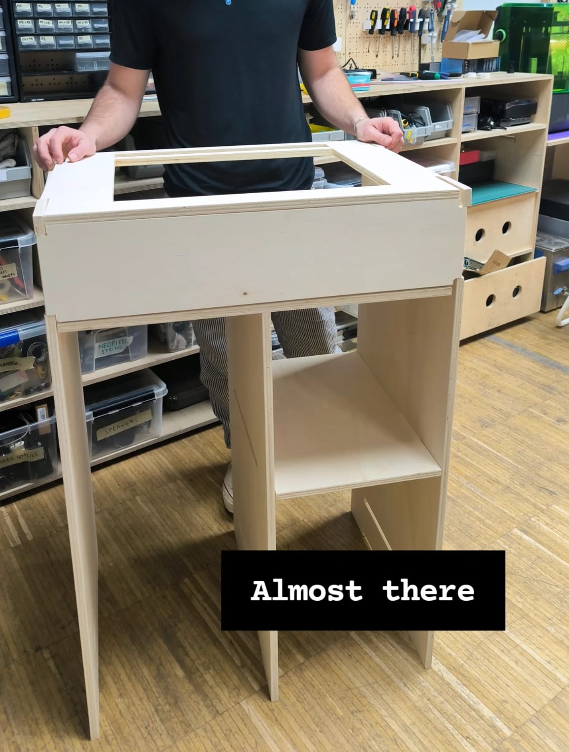
Final result
The objective of the week was to design and mill a booth with space for two turntables and a mixer on the top of the booth and space for vinyl’s underneath. I only had one board to play with this week so I decided to only mill a sample of the design in order to test the fit, rigidity and dimensions of the final design and get some feedback from the client.
Here is the prototype: