12 - Machine Week
group assignment
   - actuate and automate your machine
   - document the group project and your individual contribution
For the machine week we decided to make a Wire Bender. You can learn more about this machine here.
Individual Contribution
My principal contribution to our group’s wire bender was the stepper motor setup.
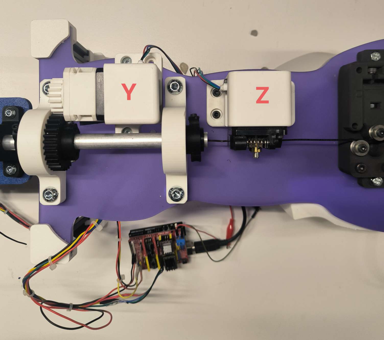
We decided to use the CNC shield to power our X (bending angle), Y (feeder) and Z (rotate bending bed) motors, along with a servo motor to move the copper bar that does the bending.
This work required me to use GRBL and to learn how to control and calibrate the motors using pyserial and GCODE, before handing over the python scripting to Gonzalo GUARNER.
I learnt much about the operation of stepper motors and the little hacks to be aware of.
The build and calibration of the different motors is given in more detail hereafter.
Stepper Motor, Driver and Operation
One of the stepper motors that we have is the LDO Motor - 1.8 Hybrid Stepper Motor LDO-57STH56-2804A #210719. The datasheet can be found here https://ldomotors.com/uploads/product_attachment/path/8/LDO-57STH_Info_Sheet.pdf.
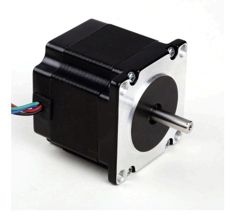
Another Stepper motor that we are using is the 42BYGH40-1.8-23A along with its datasheet https://mecheltron.com/sites/default/files/webresources/MechanicalElectroMech/StepperMotors/pdf/42BYGH_data_sheet.pdf
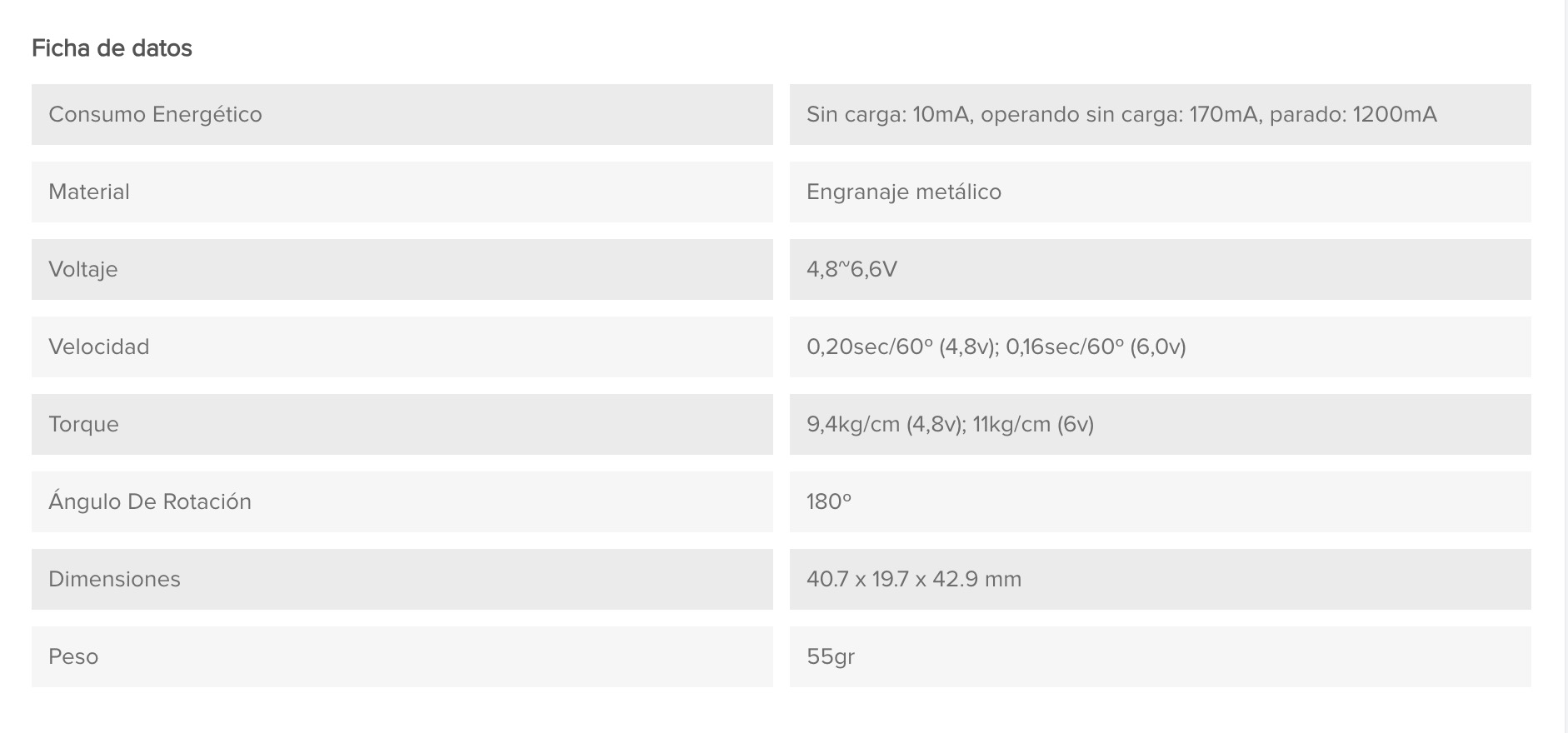
We have the SERVOMOTOR DIGITAL MG995 in stock so we will use it in our project. The data sheet can be found here. Some of the key features of the motor are given in the table below:
Setting up the Stepper Motor using a CNC Shield
References
[1] G-code cheat sheet : https://www.probotix.com/gcode_cheatsheet.pdf
[2] Marlin Gcode docs : https://marlinfw.org/docs/gcode/G000-G001.html
[3] Grbl error codes : https://resources.sienci.com/view/gs-grbl-alarm-error-codes/
[4] https://hackmd.io/@MikelLG/Bk0Ok4t61x by Mikel Llobera Guelbenzu to give the PI serial communication - GRBL description to help us define motor movements.
[5] https://cool-emerald.blogspot.com/2021/04/drawbot-xy-plotter-with-arduino-grbl.html
[6] https://www.diyengineers.com/2023/01/05/grbl-with-arduino-cnc-shield-complete-guide/
We decided to use the GRBL library from Marlin Firmware for controlling the stepper motors on the CNC shield. https://github.com/gnea/grbl/blob/master/README.md
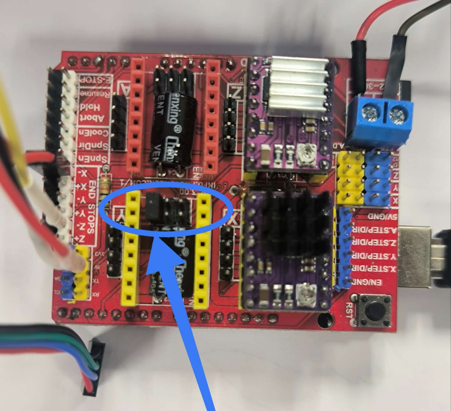
We followed the following guide to setup the motors https://www.diyengineers.com/2023/01/05/grbl-with-arduino-cnc-shield-complete-guide/ [6]
According to [5] cloned CNC v4 shields are known to have hardware issues.
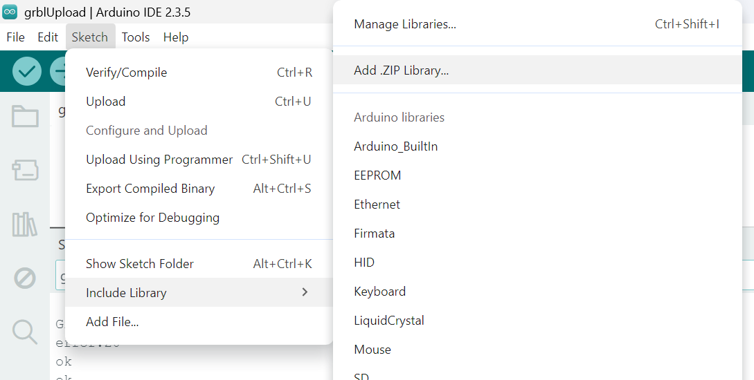
We downloaded the grbl-master file from github, then had to rezip the grbl library within on its own to then import it in Arduino IDE :
We then had to modify the config.h for our design following the steps described in [5]. The difference between the original and modified files is highlighted in the screenshots below.
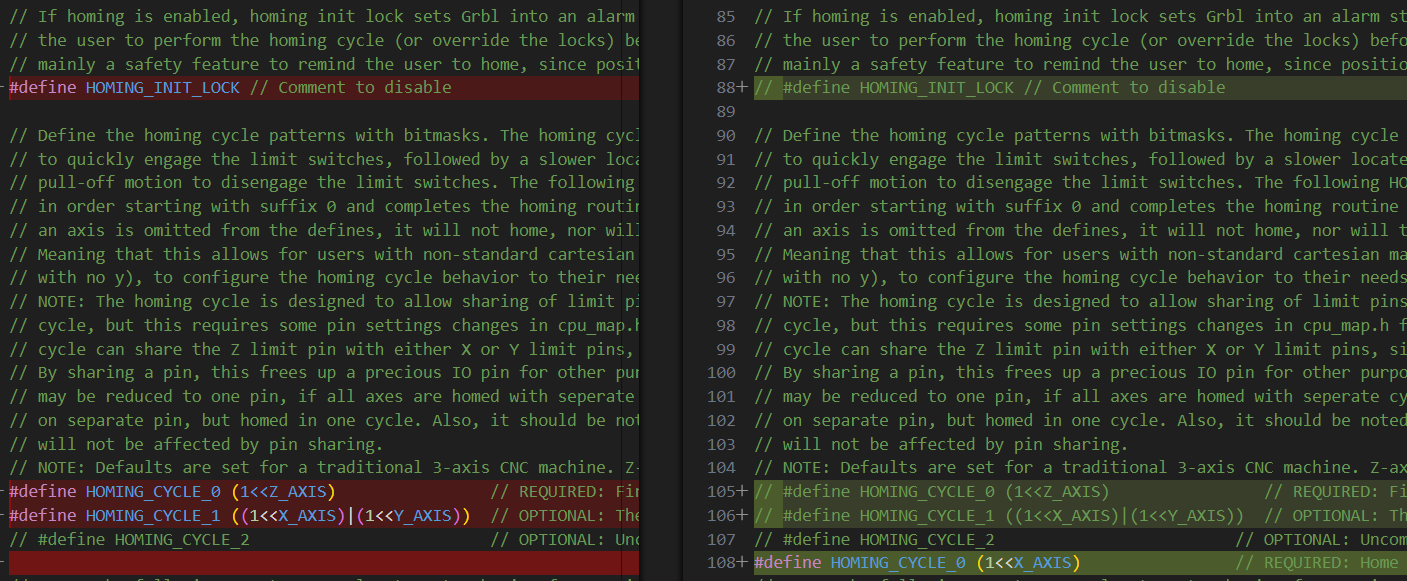
First step was to define the different motors in our design to an X, Y, Z or A from the CNC shield:
- bender motor which bends the wire by a certain angle, X
- z-rotational motor that rotates the bending plate by an angle to bend the wire on the Z axis, Y
- the feeder motor which feeds the wire a given distance, Z
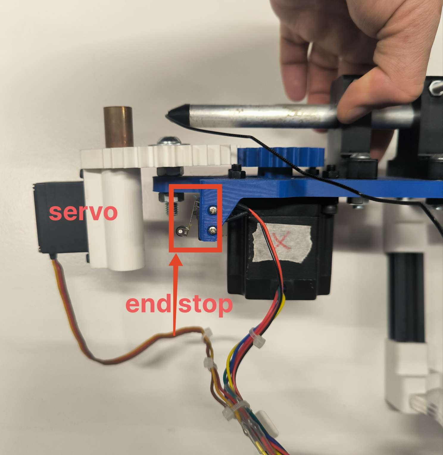
- a small servo motor to control the up and down movement of the copper piece that will do the bending
According to [5] in cpu_map.h verify that line 147 is commented and line 148 is as follows (changes PWN frequency 1kHz for Laser to approximate 50 Hz for servo):
147 // #define SPINDLE_TCCRB_INIT_MASK (1<<CS22) // 1/64 prescaler -> 0.98kHz (J-tech laser)
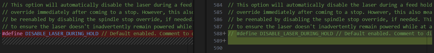
148 #define SPINDLE_TCCRB_INIT_MASK ((1<<CS22)|(1<<CS21)|(1<<CS20)) //1/1024 prescaler -> 61 Hz (for Servo)Also verify that the undesirable PWN power changing is disabled (commented):
587 // #define DISABLE_LASER_DURING_HOLDWhen compiling the Grbl there is a trick to delete all of the temporary files in the arduino folder to ensure that the Arduino IDE is takin the correct config.h and cpu_map.h files and not the old ones. https://github.com/gnea/grbl/wiki/Compiling-Grbl give trouble shooting for this step.
Stepper Motor Driver
We chose to use the DRV8825 motor drivers with the CNC shield. more details can be found on the following page:
For our design we chose to use a microstep resolution offering 1/16 steps = 3200 microsteps.
| Mode 0 | Mode 1 | Mode 2 | Microstep resolultion |
| 0 | 0 | 0 | Full step |
| 1 | 0 | 0 | Half step |
| 0 | 1 | 0 | 1/4 step |
| 1 | 1 | 0 | 1/8 step |
| 0 | 0 | 1 | 1/16 step |
| 1 | 0 | 1 | 1/32 step |
| 0 | 1 | 1 | 1/32 step |
| 1 | 1 | 1 | 1/32 step |
Calibration
The first driver took the most time as we encountered the following problems :
- not enough voltage to turn the motor connected to VMOT pin
- wires coming from the motor are not in correct order for the A1 A2 B1 B2 pins
- reference voltage and limiting current too low
To resolve 1 we simply needed to increase the voltage above 8V.
To resolve 2 we needed to identify the pairs by connecting two of the 4 wires together to see which gave more resistance. Two wires sharing the same loop will create more resistance. One pair is then connected to A1 and A2, and the other B1 and B2.
[5] explains clearly how to calibrate the reference voltage and adjust the potentiometer on the driver until the multimeter receives 0.7-0.9 V between the cathode on the potentiometer itself and the anode connected to ground. Be careful to not touch any of the other components on the driver with the cathode, as it risks to burn the driver.
The current limit for the DRV8825 is given by :
Since Rs is 0.1 ohm, the =
amps
Homing
To initiate the motor, we need to home the positioning: first installing the python serial library;
python3 -m pip install pyserial and understanding the grbl settings:
$H sends the motor to home it’s position using grbl. It will set the point where the end stop is triggered as 0 for the motor. It will home twice, first seeking the home at a faster speed and then refining the home at a slower speed.
If it starts to move in the wrong direction we need to invert the direction using Gcode : $23=1
G92 X0Y0Z0 allows the user to set the origin at the current position.
Bending motor calibration
Here we are going to calibrate the bending motor, X, to rotate the bending platform 1º with the command G0 X1, which would typically move 1.8º.
We initially have 1.8º per step per 200steps. We also have two gears with 18 and 30 teeth, the former being the one coaxial and attached with the motor. Therefore we have a 5/3 gear ratio.
360 / (200*5/3)= 360º/333.3 = 1.08º per step of the end gear.
$100, $101 and $102 set the steps/mm for the X, Y and Z motors respectively. We need to modify this so it is steps/º. Not only that we need to consider that we are using a 1/16 microstepping.
for the X bending motor, $100 needs to be set to
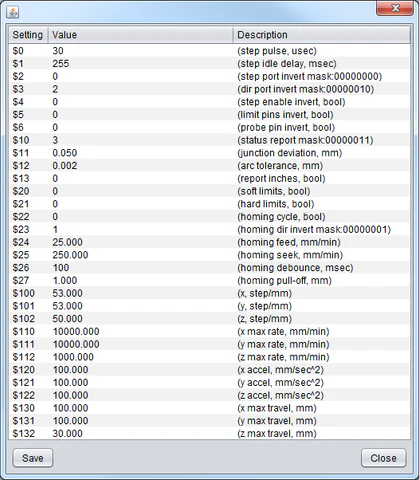
These are the default values for the Arduino board and CNC shield, retrieved by entering ‘$$’ in the serial monitor.
$0=10
$1=25
$2=0
$3=0
$4=0
$5=0
$6=0
$10=1
$11=0.010
$12=0.002
$13=0
$20=0
$21=0
$22=0
$23=0
$24=25.000
$25=500.000
$26=250
$27=1.000
$30=1000
$31=0
$32=0
$100=250.000
$101=250.000
$102=250.000
$110=500.000
$111=500.000
$112=500.000
$120=10.000
$121=10.000
$122=10.000
$130=200.000
$131=200.000
$132=200.000
These are the values we change for the Bender
$4=180
$10=2
$22=1
$23=1
$24=500
$100=14.815
$110=5000
$120=100
We start by homing X and then move on to calibrate the Feeder, Y in the same manner as it has a similar gear ratio.
We then move on to calibrate the feeder, Z. The feeder pulls the wire through the motor at a given feedrate in mm/min. $102 is the number of steps the Y-axis motors needs to move to travel 1 mm. By trial and error we determine $102 = 95
$1 = 180 allows the motors to remain enabled with full power even when not solicited (range between 0-255) to maintain position and hold the wire position.
Calibrate Servo Motor
The following is inspired from the following drawing bot [5].
For the servo, as mentioned previously, we hack the stepper motor GRBL code by modifying the config.h and cpumap.h, adding the following lines of code :
cpu_map.h : comment line 147 and add line 148
147    // #define SPINDLE_TCCRB_INIT_MASK      (1<<CS22)               // 1/64 prescaler -> 0.98kHz (J-tech laser)
148    #define SPINDLE_TCCRB_INIT_MASK ((1<<CS22)|(1<<CS21)|(1<<CS20))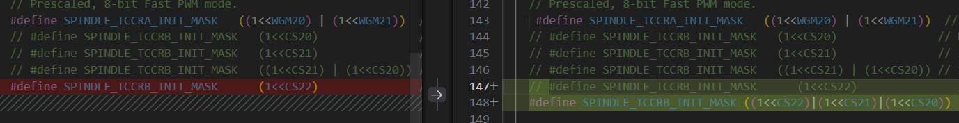
The following commands are used to control the servo motor so that the bending pipe is either down or up:
M03 S120    // down position for skip
M03 S50     // up position for bend
Using the Z+ endstop pin to control the servo. The servo to copper bar mechanism can be a little temperamental, so these S values have to be changed from time to time using intuition, as they cannot be zeroed with G92.
Optimised Stepper motor settings:
The GRBL setup for the motors is as follows:
 $1=180
 $2=0
 $3=0
 $4=0
 $5=0
 $6=0
 $10=2
 $11=0.010
 $12=0.002
 $13=0
 $20=0
 $21=0
 $22=1
 $23=1
 $24=500.000
 $25=500.000
 $26=250
 $27=1.000
 $30=1000
 $31=0
 $32=0
 $100=14.815
 $101=14.815
 $102=95.000
 $110=5000.000
 $111=250.000
 $112=250.000
 $120=100.000
 $121=20.000
 $122=20.000
 $130=200.000
 $131=200.000
 $132=200.000
Improving the Y axis rotation
We noticed that the gears on the motor would slip under the weight of the rotating platform hosting the X motor at angles above 26º. In order to prevent this we decided to look for a suitable gear reduction design to the Y NEMA17 motor. We found the following design :
https://www.printables.com/model/281222-nema17-planetary-gearbox/files
We took the following .stl file. modified it to our design and uploaded the different reducer parts into chitabox for print. The first print with the resin printer did not turn out correctly as I did not separate all of the parts correctly.
We reprinted with the Bamboo X1 Carbon printer in PLA to save time.
The reducer has allowed us to hold the position past 90º which is fantastic.