09—Input Devices
Assignment
- Group assignment:
- Probe an input device(s)'s analog levels and digital signals
- Document your work on the group work page and reflect on your individual page what you learned
- Individual assignment:
- Measure something: add a sensor to a microcontroller board that you have designed and read it.
Requirements Checklist
- Linked to the group assignment page
- Documented what you learned from interfacing an input device(s) to your microcontroller and optionally how the physical property relates to…
- Documented your design and fabrication process or linked to the board you made in a previous assignment
- Explained the programming process(es) you used
- Explained any problems you encountered and how you fixed them
- Included original design files and source code
- Included a ‘hero shot’ of your board.
00— Week Reflection
Even though I did not finish the assignment this week felt like a major success. I was able to integrate flux.ai as a full replacement for KiCAD in my PCB design workflow. I was also able to re-jog my memory about how to send in PCBs for manufacture. So for me this was an important week to dial in my workflow and priorities for PCB design.
01—Link to Group Assignment
For the group assignment we each did different sensors as separate 3 person groups. The sensor we chose was a rotary encoder. I picked it because I remember hearing they were difficult to interface with and it is something that I know can be very useful in control interfaces and accurate positioning for motors of all kinds. I did not understand their working principle or how to interface with them before we spend about 2 hours trying to figure it out. I was really surprised how we went from zero knowledge about this to a pretty solid understanding of how they worked. Similarly we chose not to use a library initially, but after drafting our simple working code it made sense why a library would be used to add additional functionality and accuracy.
02— Primer About Input Devices (From Class Notes)
Notes from class a primer on input devices
- All sensors can be broken up into roughly two categories passive and active.
- Many sensor (I think mostly applies to analog) need a pulldown resistor 10k is a standard value.
- Digital read (digital sensor) vs analog read (analog sensor) functions in Arduino are used to read sensor data.
- Below is an example of how to use analog read to read the value of a potentiometer through
analogRead. Here the center pin is your GPIO pin the zero value for you pot can be left or right this is typically read in the code as the starting position of your pot v+ will be your end position.void setup() { pinMode(17, INPUT); Serial.begin(9600); } void loop() { int lecture = analogRead(17); Serial.println(lecture); delay(50); }
- I think all analog sensor will need a voltage divider. Basically if you are trying to read a voltage from something like a light sensor (which provides variable resistance based on temperature) you need to add another resistor (like 10k). This is because you need to measure the value “in circuit” in order to measure the changing value. Think of it terms of potential energy if you don’t have the second resistor what you measure can only be the absolute value of GND or VCC.
Other topics worth going into depth are
- Common approaches and considerations around button debouncing
- Choice of diodes type and specifications to prevent back feeding
02—V2 Akrasia Stepper PCB Design Research
About the Project
The Akrasia project was an art work I was developing for several months late in 2024. The project was never finished. What stopped the project was issues that arose during developing the PCB / ECAD. I had already spent many hours trouble shooting it after I had done this I got busy and became tired of the project so never implemented the changes. With the knowledge I have now I decided to give the PCB a second look and try to get a new version sent off to be manufactured. I can see the board being re-used for other projects which is why I have decided to unearth it and finish the PCB.
Some of the original issues I encountered with the first PCB were:
- Blew up an electrolytic capacitor when first connected
- Tons of UART serial communication issues that were both hardware and software related.
- Fried a Xiao (protection diode)
Concepts I need to research to complete the project
In the following sections I am reviewing some of the concepts that need a closer look to address the issues my PCB had.
- UART Communication — review of protocol basics
- TMC Stepstick 2209 (Bigtreetech)— consolidate and summarize notes
- USB C PD—Power delivery limitations and requirements
- Explanation: I selected +12V from the USB C trigger board for the original PCB design. This was a bad choice because +12v is an optional USB C meaning manufactures of power supplies sometimes do not include this capability. With what I know now I will be using +20V exclusively for my USB C projects. I am doing this because it gives me the highest possible current rating (100W) at the more common SPR USB C PD spec.
- Diodes to prevent back feeding—Selection and placement of diodes for +5V MCU input to prevent back feeding when XIAO is powered through its onboard USB C port. I simply did not have these on the first PCB design. This alone could have been a primary source of the issues I had.
UART Communication
(Universal Asynchronous Receiver Transmitter)
- UART sends data serially vs parallel (parallel would require multiple data lines?) so it only sends 1 bit at a time. It does not use a clock line which is why setting a predefined baud rate is important so both sides communicate at the same rate.
- UART frame format
- A start bit — Initiates frame start by sending logic low (0)
- Data bits — typically 8-bit, but can be 7-bit or 6-bit
- 8-bit can provide 256 values or a whole byte of data enough to send an ASCII character
- 7-bit can provide 128 values
- 6-bit can provide 64 values
- A parity bit — is not always present but exists to error check (I don’t understand how this actually works)
- A stop bit — is used to signal the end of the frame two can be used for redundancy
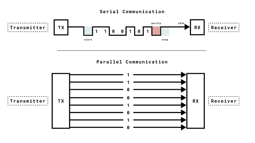
- Devices require a common ground
- Baud rate is the speed of the communication on both encoding and decoding. In a parallel data stream this happens on both ends.
- SPI and I2C are successors of UART. I2C seems to be the best choice consistently if it is available. It does not seem stepper drivers are typically designed for UART communication.
Programing UART in IDE For Arduino Brand Boards
- Regular USB communication to classic Arduino boards is sent through a serial port (RX /TX)
- D0 is TX D1 is RX typically
- Serial1 is used for RX/TX pin communication.
- Common baud rates are
9600,115200,4800, and57600. Higher baud rates require tighter timing synchronization and can become more error prone if noise is not managed properly.- Sample Arduino code for Initialization and setting baud rates
Serial.begin(9600); //init communication over USB
Serial1.begin(9600); //communication over RX/TX pins
- Sample Arduino code for Initialization and setting baud rates
- Flow Control uses stop start commands to compensate for differences in timing between devices (I am guessing baud rate differences?)
- Common syntax for the Arduino serial class
begin()- begins serial communication, with a specified baud rate (many examples use either 9600 or 115200 ).
print()- prints the content to the Serial Monitor.
println()- prints the content to the Serial Monitor, and adds a new line.
available()- checks if serial data is available (if you send a command from the Serial Monitor).
read()- reads data from the serial port.
write()- writes data to the serial port.
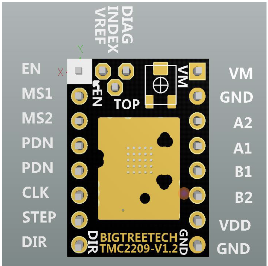
TMC Stepstick 2209 (Bigtreetech v1.3)
Basic Specs
- Continuous drive current 2A peak current drive 2.8A
- VIN Range 4.75V ~ 28V DC
- VIO 3~5 v
- It is very important for the VIO to be the same voltage as the MCU sending the messages. So in the case of the XIAO it must be 3.3V otherwise you need a logic level converter.
- Micro stepping: 2,4,8,16 (selected through pull ups or downs on MS1 and MS2) or 256 (can only be selected over UART serial)
- I am not sure if all micro stepping control can/should just be configured over UART or if MS1 need to be managed actively through resistors.
- Operational Modes: STEP/DIR or UART
- Default PDN_UART pin is pin 4 this is a single pin UART managing both input and output serial to use pin 5 you must move the resistor.
- UART is default enabled
Pinout
- Diag is a diagnostic pin for stall guard or collision detection (I would be wary about using this in place of limit switches, but people say it works)
- Vref is a reference pin for vref setting this might be necessary for proper digital vref setting it also just might be a spot to probe the value… not sure. I will not be using it and will opt to set this manually for reliability.
Essential TMC 2209 UART Commands
| UART Command | Description |
| driver.begin(); | Initializes UART communication with the TMC2209 driver. |
| driver.toff(5); | Enables the driver by setting a non-zero off time (must be >0). |
| driver.rms_current(mA); | Sets the motor RMS current in milliamperes (e.g., driver.rms_current(500);). |
| driver.en_spreadCycle(false); | Disables spreadCycle to enable stealthChop mode for quiet operation. |
| driver.pwm_autoscale(true); | Enables automatic current scaling for smoother operation in stealthChop. |
| driver.microsteps(steps); | Sets the microstepping resolution (e.g., driver.microsteps(16);). |
| digitalWrite(DIR_PIN, HIGH/LOW); | Sets the direction of motor rotation (hardware pin control). |
| digitalWrite(STEP_PIN, HIGH/LOW); | Generates step pulses to move the motor (hardware pin control). |
Advanced UART Commands
| UART Command | Description |
| driver.IHOLD_IRUN(hold, run, delay); | Sets hold and run currents and delay between them. |
| driver.TPOWERDOWN(time); | Sets delay time before power down when the motor is idle. |
| driver.TPWMTHRS(threshold); | Sets the upper velocity for stealthChop operation. |
| driver.TCOOLTHRS(threshold); | Sets lower velocity threshold for switching to coolStep or stallGuard. |
| driver.sg_stall_value(value); | Configures the stall detection threshold. |
| driver.coolstep_min_speed(speed); | Sets minimum speed for coolStep current control. |
| driver.GCONF(registers); | General configuration register for advanced settings. |
| driver.pwm_autograd(true/false); | Enables/disables automatic amplitude scaling for PWM. |
| driver.pwm_freq(value); | Sets the PWM frequency for stealthChop mode. |
| driver.blank_time(value); | Sets the blank time (off time) for the driver. |
Other Important Configuration Notes
- Setting Vref → Clockwise rotation (EN as top reff.) reduces current
- Use 5th Pin as your UART receiver. The manual still recommends splitting the two lines into the PDN in and adding a 1k resister to the incoming TX line.
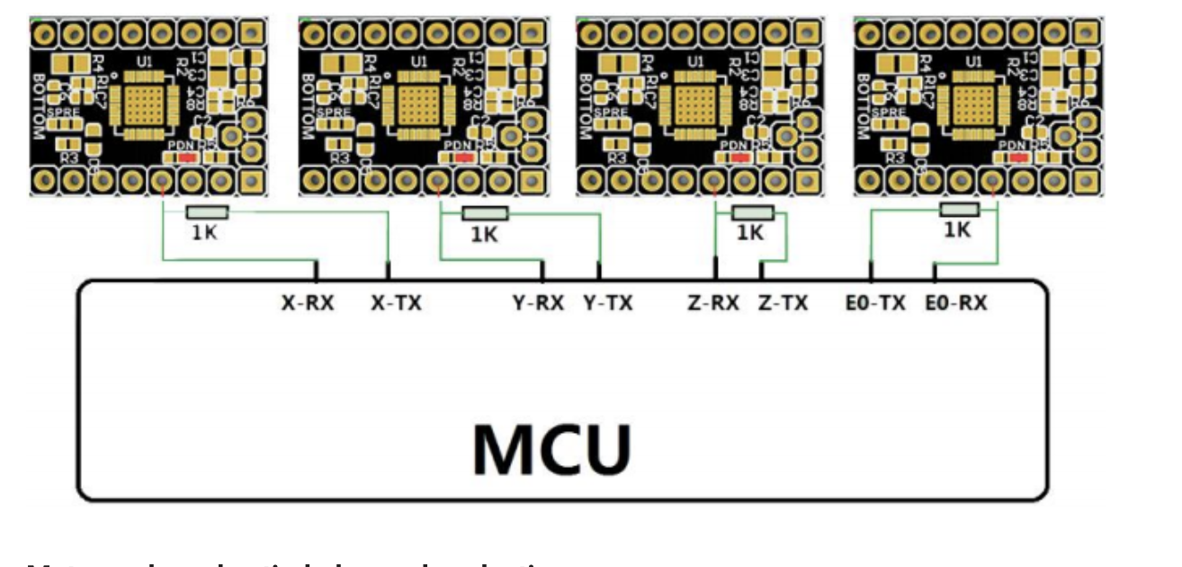
- Do not plug in in wrong orientation it will fry your driver
- Output current is RMS so your DMM reading will make it seem like the driver is putting out significantly lower current than it actually is. You need an oscilloscope to actually test this.
USB C PD Specifications
- PD now comes in two flavors SPR (Standard Power Range ) and EPR (Extended Power Range) below are all of the different voltages, PD types, and related considerations.
Available Current and voltages Power Delivery Profile Range Special Considerations SPR [3A] 5V, 9V, 15V, 20V SPR [5A] 5A: 20V Needs a 5A capable power cable EPR [5A] 5A: 28, 36, 48 PPS (for SPR) (variable)→20V Not a requirement and not always listed in charger capabilities AVS (for EPR) (variable)→48V Might not even exist in chargers that can be purchased as EPR is still very new
- Technically you can get in between voltages like 3.3 V, using a standard within PD called PPS for SPR and AVS for EPR-range chargers. Not a requirement, but not uncommon for many chargers to have PPS support which will typically be written on the label. I would not mess with PPS/AVS because neither are widely adopted yet.
- When purchasing USB C PD cables for certain use cases SPR 5A cables (versus 3A standard cables) are just labelled 100W and EPR Cable are just labelled 240 W typically. 240W EPR chargers basically don’t exist for purchase as of writing this [2025].
Adafruit HUSB238 — Specifications
Core Features
- VOUT → 5[default],9,12,15,20
- Max A out → 1A [default], 2A, 3A [leave all current jumpers open]
- I2C control → used for dynamic voltage control (cant think of any reason why I would need this)
- My configuration: All current pins open (allowing max 3A) All V pins open (allowing max 20v)
Important note: Default voltage is 5V 1A so if things are not working this is what you will be reading on your DMM. Most chargers even nice ones… even ones that say they do will sometimes not give you 12v even if you have it selected use PD chargers that you can actually get this voltage out of over PD. Since 20V gives the highest amp output I am now defaulting to 20V IN for all of my USB C PD projects.
Diodes to Prevent Back Feeding
- Shottkey diodes are supposed to be appropriate for this. I consulted Flux.ai and this was its recommendation. It also provided a specific part recommendation and required positioning. At the moment I will not dive too far into this because I can ask people at fab academy to verify the details of this.
03— ECAD for V2 Akrasia Stepper Control PCB
What I am optimizing for in the new design. Speed of design + it working. I tried to tackle too much with the first design. Eventually I want to design my own power section, but for now I am just going to use off the shelf 3A buck converters.
Primary changes
- Adding proper handling of the TX and RX lines. Meaning the TX from the MCU now has a 1K resistor as it was supposed to.
- Added the Shottkey diode to prevent back feeding
- Changed out the original 5v converter to something that can be sourced that has an accurate library component in Flux.
Flux Design Knowledge (picked up as I went)
I learned or relearned some of this during the actual design process. As I went I figured the information is more useful as a separate section.
Trace thicknesses (from Flux copilot recommendations)
- +3V3 rail → .5mm (moderate current demands)
- +5V → .5mm (moderate current demands)
- +12V → 1mm (medium current demands)
- UART → .25mm (general recc for digital signals)
- It also suggests that impedance matching is not important for these lines as they are not actually considered high frequency.
- GPIO for XIAO → .25mm (general recc for digital signals)
Ground Plane
- Copper fills are enabled by default vias are created by default in a grid format (but can be tweaked to merge top and bottom grounds)
Set Preferred trace widths
- To set your projects trace thickness create a ruleset call it Preferred Trace Widths and then in
layout rulesclick add and selectPreffered Trace Widthsinput your numbers in separated by a space. I am using the values.25mm .5mm 1mm.
- Press
wto cycle through trace widths.
Common routing shortcuts
- Flip elbow direction
f
- Change Layer
v
Notes from speaking with the developers of Flux.ai on their slack
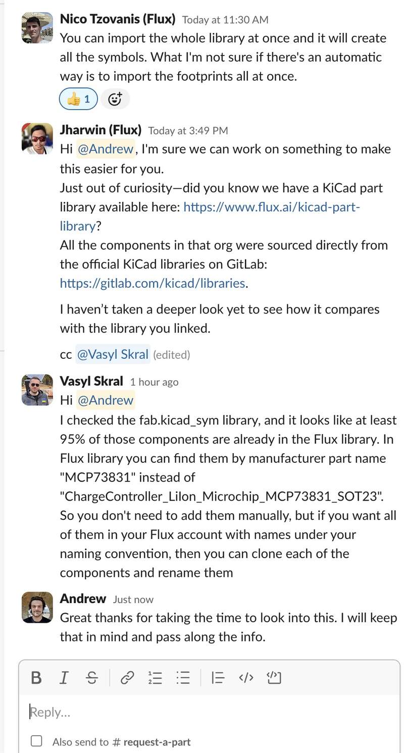
I chatted with the developers of flux about importing all of the KiCAD FAB library assets. I figured they might have a faster way to do this before I committed to the arduous process of converting all of the things from the library I needed for my PCBs. They told me that 95% of the items are already a part of the library and the best way to search them is by part name. Below I have included a screenshot of the conversation.
PCB Design Process in flux
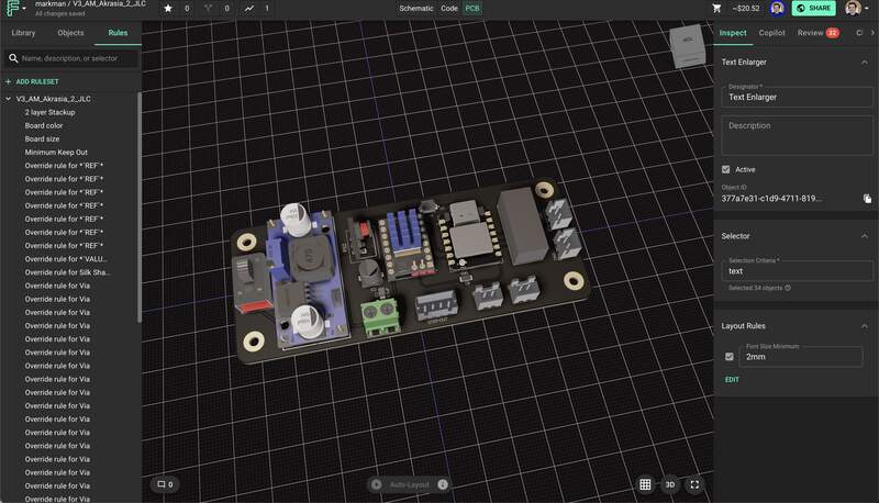
- Schematic was about 70% complete. I worked for about 4 hours to make sure I was not doing anything stupid. Mostly I added the changes and reworked the net portals so that they made more sense and were used more frequently to simplify the schematic.
- Spent 3 hours getting the footprint layout into a good placement for routing traces… only for flux to… delete it… because I did something the software did not like… So I cloned the project and started over. The second go footprint design went much faster.
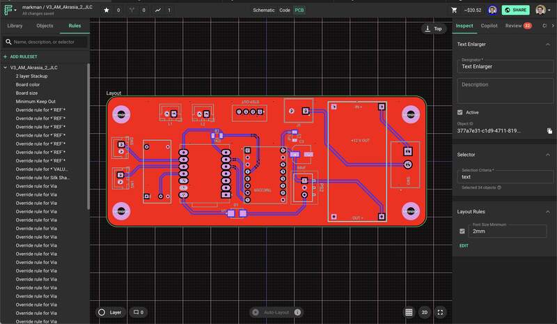
Some things I re-encountered about PCB design were:
- mil is the standard board unit used it is .001 inch or .0254 mm
- .01” or 2.54 mm is a typical pin spacing and electronics design size module. Often PCBs will be designed at some multiplication of this 2.54mm.
- After checking over the design I crossed my fingers and set up the design specifications on JLC PCB this took about an hour and a half to refresh myself on what manufacturing constraints were relevant to me.
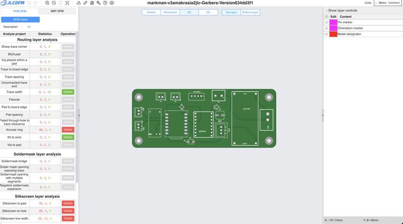
- I experimented a bit with automating the BOM and or having PCB way do the PCB assembly, but decided the juice was not worth the squeeze in this case.
How to add a new part from a KiCAD library to Flux Library
I am writing this for posterity. There are more details, but here are the broad strokes. So I don’t forget how to do this.
- Upload your KiCAD sym into the main hub (before you make a project)
- This will automatically import details and symbol.
- Add your footprint and step in the asset manager panel.
- You now need to link them in the footprint panel mode. You do this by selecting the footprint object in the objects panel adding an asset rule and selecting the footprint .mods file for the component.
- The same approach is taken for the 3D step model, but by creating a new 3D model object in the ‘objects panel’ adding asset selector and then your 3D model.
- Last step is publishing the part.
- Part needs to be reopened in a fresh document to view the custom symbol.
04—ECAD for final Project Prototype
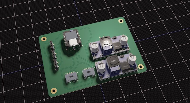
PCB Design Process in flux
I started a new project in flux to design my I2C final project board. I did some broad searching to confirm how to create an I2C bus. This design process was very iterative I continually got to the end of the design then went back to the beginning to swap components so that the PCB could be milled at our proto lab. I found this back and forth a much easier workflow than attempting to get everything polished on the first go.
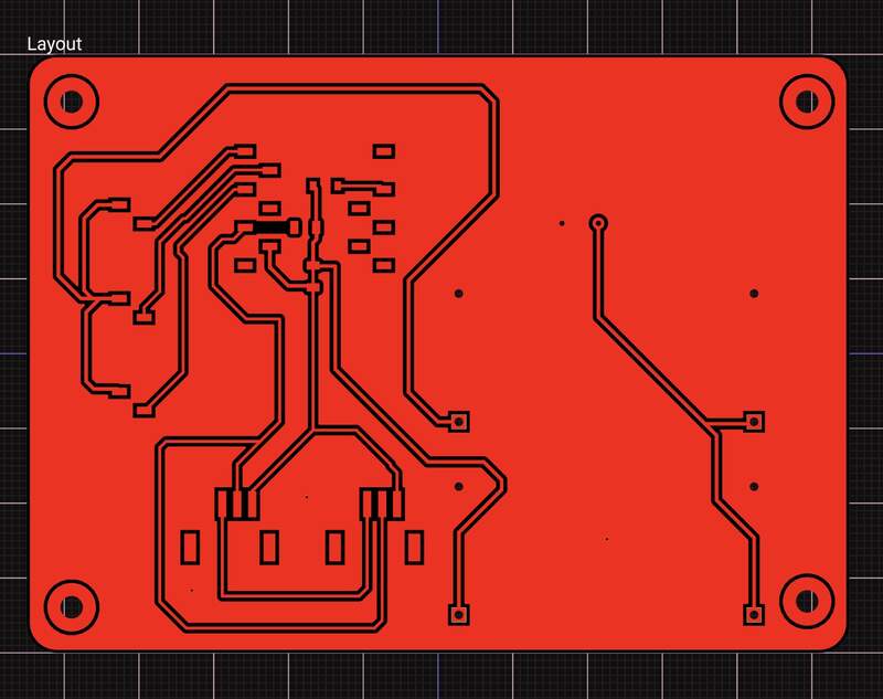
- Designed board to be single layer. I had major issues routing all of the traces on a single layer and given the required oreintation I am not sure if it would have been possible. For the sake of time I decided to delete 2 of the I2C connectors.
- I used a very stupid approach to creating the 2D design file for the PCB by taking a screen shot the Flux app and processing it in illustrator … this is not for the faint of heart… It did work though.
- Components were selected and prepped for assembly.
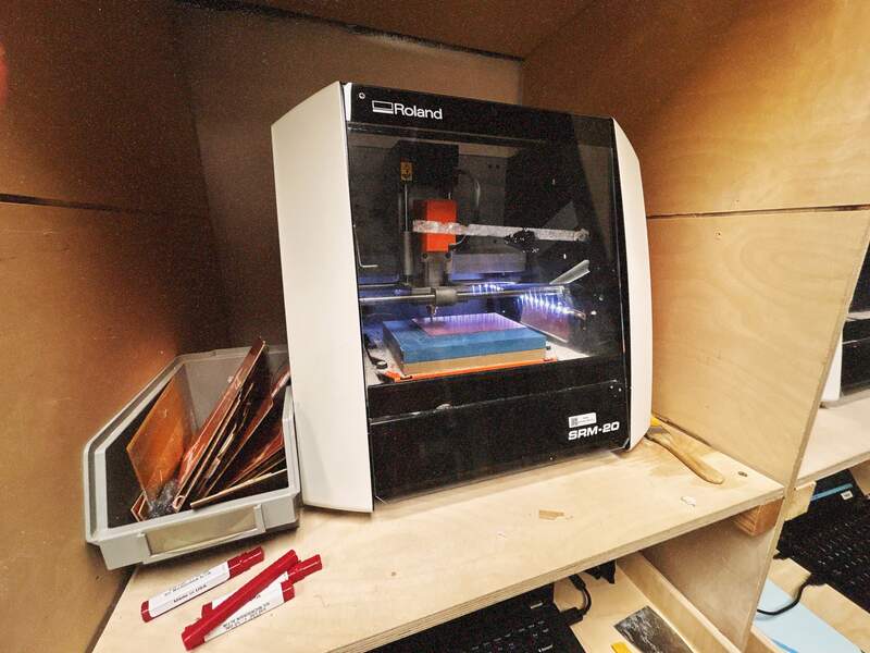
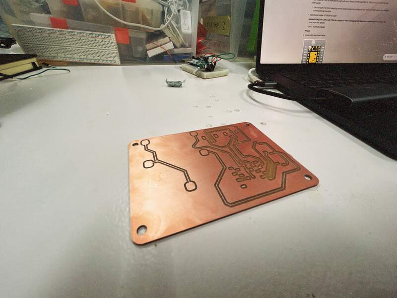
- Initial PCB milling incorrectly cut the outside line of the holes. This almost definitely was a setting I missed when configuring the Mods project. The trace quality was also very bad. This PCB already needed jumper wires and I had made some compromises with the SMD pads that would have made mounting the buck converters challenging I decided to recut the PCB.
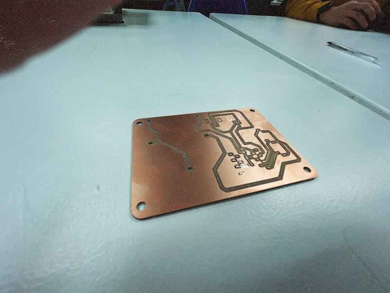
- Another Board was recut with slight modifications for better surface mount compatibility.
Board assembly
- Board was assembled I utilized SMD pin sockets extensively mount through hole component on the single layer milled board.
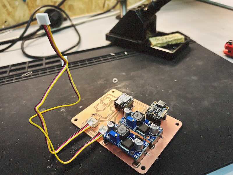
- Major issues were discovered and extensive testing was needed to troubleshoot. The primary issue was not getting power to the Xiao through the buck converter. Solving this issue was not a linear process. After poking around on the milled board I decided to try to power up my test xiaos connected to the power rail of the board. My current guess is that the Xiao just do not like being powered by the 3v3 pin even though their documentation says they can be. Its possible that my switching buck converters are just too noisy to use for this purpose.
- This actually meant a significant amount of cutting and jumping traces to get the board to receive 5V and still maintain an I2C line at 3v3 logic.
- Even after all of this I was getting intermittence from the Xiao I was using. The Xiao would run for 30 seconds and then shutoff. To solve this I worked with Dani to confirm more detail what was working and what wasn’t we did a few different tests. Mostly around confirming the MCU itself was operational. We were able to confirm a few things.
- The C6 Xiao was in fact not working.
- We ran some code to print serial from the Xiao C3 to serial monitor when disconnected to the Milled board and confirmed it was operational.
- We connected the Xiao to the milled board and confirmed it was operational in this context.
- We powered up the power circuit then plugged in the USB C for serial communication. This produced no serial return.
- Dani had suggested that the serial send on the Xiao just might be getting blocked but the unit itself was running the code. Similarly he used a very interesting test code to print a count that would print right after initialization. This meant if something was causing the MCU to reset it could be observed from the serial output.
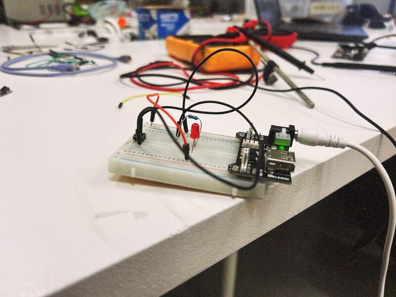
- Dani wrote test code for an external test using an LED. We confirmed that the LED worked and that for some reason having dual power inputs would in fact block the XIAO, but that the Xiao could intelligently handle the dual inputs by choosing the first power source and blocking the second.
long runs = 0;
int led = D10;

void setup() {
  Serial.begin(115200);
  pinMode(led, OUTPUT);
}

void loop() {
  // put your main code here, to run repeatedly:
  Serial.print("heyyy there... I see ");
  Serial.print(runs);
  Serial.println(" elephants");

  runs += 1;

  blink(runs % 10);

  delay(500);
}

void blink(int times) {

  for (int i = 0; i < times; i++) {
    digitalWrite(led, HIGH);
    delay(100);
    digitalWrite(led, LOW);
    delay(50);
  }
}
- I did the last bit of modifications to get the grove connectors up and running.
- The final board has several patch cables and cut traces. I will admit this is not a great final PCB, but for this week it will do. I plan to do a significant overhall that will represent a more final design including additional I2C ports. Similarly, the final PCB will get sent this really is a process for me to root out my own faulty reasoning and PCB design decisions.
05— Input Testing on My Eval Board… Finally
I am doing this section in the follow up week (output devices) because it took until now to get development board up and running.
- For my input device I chose a grove I2C based sensor. In particular the grove temperature and humidity sensor V2.1. I had this on hand and I am interested in the workflow of integrating I2C sensors because it really seems to be the superior communication protocol. I see myself trying to create board that utilize these kind of sensors as much as I can.
- I started by checking the Seeed wiki. I found this example code and the required library: https://github.com/Seeed-Studio/Grove_Temperature_And_Humidity_Sensor
// Example testing sketch for various DHT humidity/temperature sensors
// Written by ladyada, public domain
#include "Wire.h"
#include "DHT.h"
#define DHTTYPE DHT20   // DHT 20
/*Notice: The DHT10 and DHT20 is different from other DHT* sensor ,it uses i2c interface rather than one wire*/
/*So it doesn't require a pin.*/
DHT dht(DHTTYPE);         //   DHT10 DHT20 don't need to define Pin

#if defined(ARDUINO_ARCH_AVR)
    #define debug  Serial

#elif defined(ARDUINO_ARCH_SAMD) ||  defined(ARDUINO_ARCH_SAM)
    #define debug  SerialUSB
#else
    #define debug  Serial
#endif

void setup() {

    debug.begin(115200);
    debug.println("DHTxx test!");
    Wire.begin();

    /*if using WIO link,must pull up the power pin.*/
    // pinMode(PIN_GROVE_POWER, OUTPUT);
    // digitalWrite(PIN_GROVE_POWER, 1);

    dht.begin();
}

void loop() {
    float temp_hum_val[2] = {0};
    // Reading temperature or humidity takes about 250 milliseconds!
    // Sensor readings may also be up to 2 seconds 'old' (its a very slow sensor)


    if (!dht.readTempAndHumidity(temp_hum_val)) {
        debug.print("Humidity: ");
        debug.print(temp_hum_val[0]);
        debug.print(" %\t");
        debug.print("Temperature: ");
        debug.print(temp_hum_val[1]);
        debug.println(" *C");
    } else {
        debug.println("Failed to get temprature and humidity value.");
    }

    delay(1500);
}
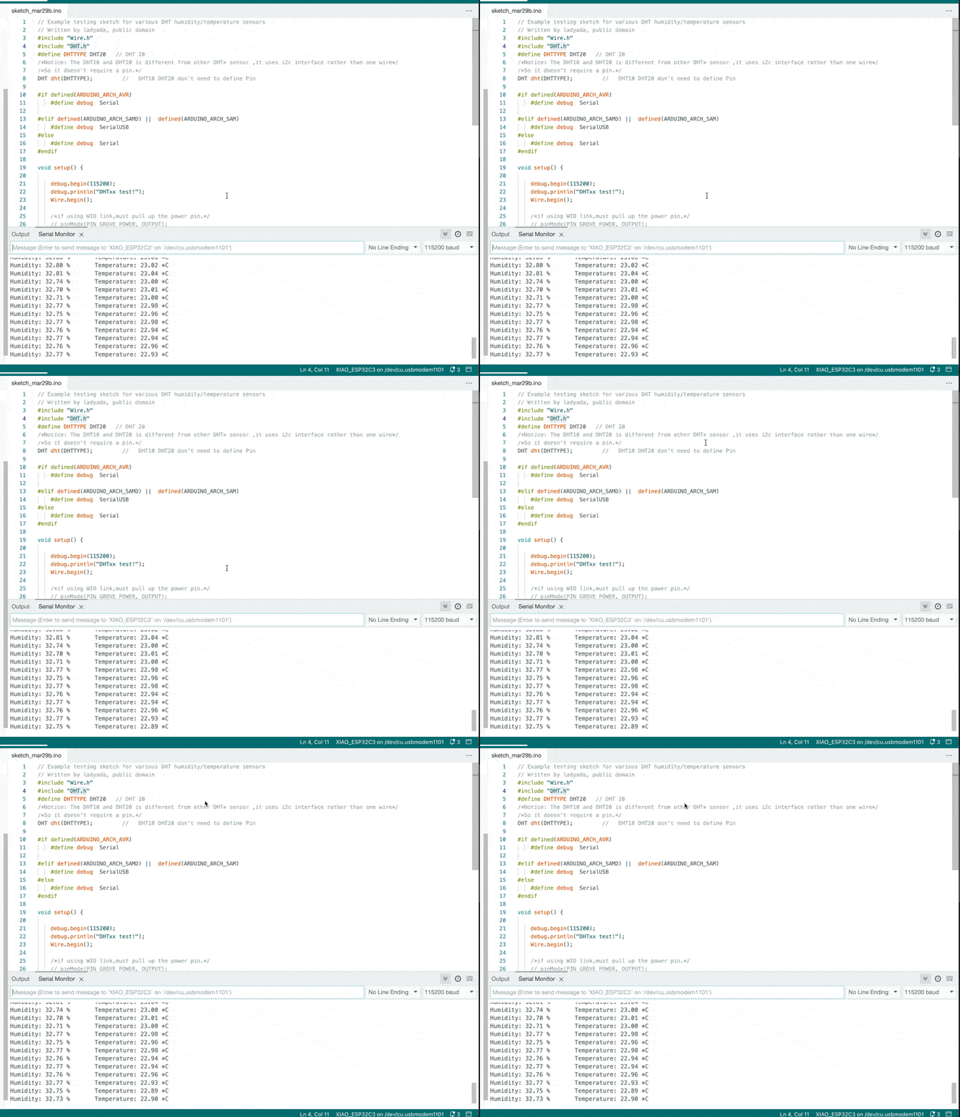
- Ran the example code compiled an uploaded the example code. Interestingly the I2C bus had no issues with me plugging or unplugging the sensor.
Project Files
References
- USB C Charging standards
https://hackaday.com/2023/01/09/all-about-usb-c-power-delivery/
