07— Computer Controlled Machining
Assignment
Task: Computer-Controlled Machining
- Group assignment:
- Complete your lab’s safety training
- Test runout, alignment, Fixturing, speeds, feeds, materials and toolpaths for your machine
- Document your work to the group work page and reflect on your individual page what you learned
- Individual project
- Make (design+mill+assemble) something big
00—Reflection
This was a big refresh for me and an exploration in taking things a step further with design for CNC routing. It has been about 2 years since I have created a design for CNC routing. From the past I remember how detail centric and intensive the setup process is. It was validating that I discovered once again how much effort it takes to create a good design and good CAM for CNC routing.
That said part of getting good results is tied to understanding the machine you are working on intimately. CNC machining is not 3D printing. As such each machine has its own workflow and limitations that take some time to get the hang of. I am not sure what or how much CNC routing I will be doing in the future, but when I do another project on the IAAC CNCs I will plan to do design a specific test file that will test all of the potential problem zones of my design. This will hopefully improve the component fit and decrease time spent post processing.
01— Group Project
Here is a link to our group project. The group project was just the test with our teacher. All in all this would have been more useful had we not lost the test pieces during the design phase ;). Ultimately though this ended up not impacting my joinery because the plywood we we chose to use is quite soft. However, while I had known the difference between upcut and downcut bits, step over etc. I had to re-remember all of these terms and why they were relevant.
02— CNC Basics
TLDR of CNC Routing
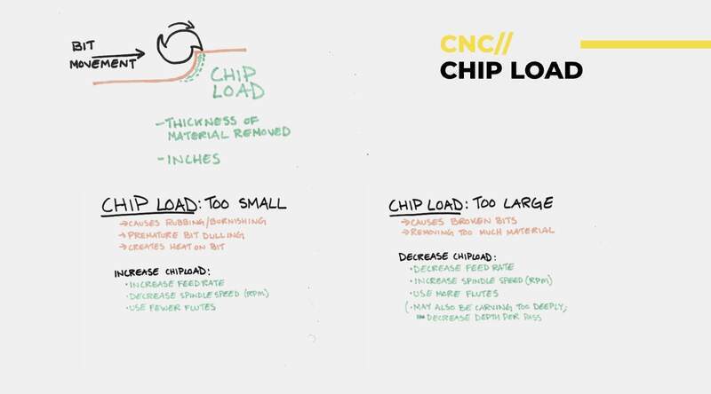
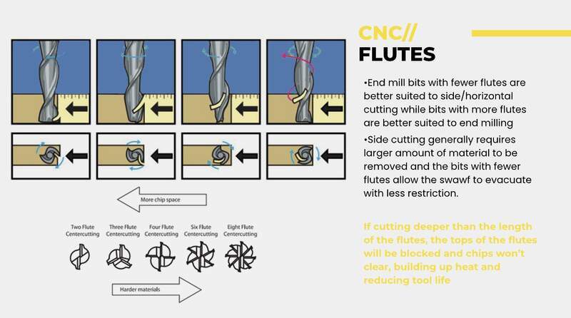
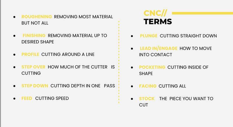
- If the baby is screaming (it needs) more food if its roaring you are feeding it too much.
- Climb (racking the surface) vs conventional shoveling the (surface). Climb will increase speed at the expense of edge quality.
- Typical profiling endmills flat and are
up cutdowncutorcompression- Up cut
- Down cut
- Compression
- Several variables that decrease precision by order of importance are sharpness / newness of bit, rigidity of the machine, proper installation of the collet, and nominal accuracy of the spindle itself. Ultimately, like the laser the machine precision needs to be tested. If the feed rate / step over / depth of cut is too aggressive positive offset from the nominal value as a result of chattering or grabbing additional material.
Common Fixturing Approaches
- Wood screws
- In class Dani / Josep said they place screws in a grid and mark them before running the CNC.
- In the past I worked at a place that used dry wall screws instead of wood screws. This had the advantage that they typically broke if they came in contact with the endmill. However, they could also sheer easily when driving them leaving the shank behind on the CNC bed. Pros and cons I guess. Potentially a trim head wood screw would be the best of both worlds.
- Wooden nails
- Never have tried this I am not sure how you would remove the final piece.
- Plastic pin nails
- Are my favorite and are great in a production scenario when working with plywoods. These are a bit more expensive need a special pin nailer and do not go through hardwood. To remove the board all you have to do is sheer them by bumping the board with a mallet.
- T slot clamps
- Low profile tiger claws are quite nice as they wedge the material and can create a good hold.
- Adhesive tapes
- Carpet tape was my go to in the past out of lazyness. It does add an to the stock height though. Leftover tape needs to be removed and it can pull thin veneers.
- Banner tape is lower profile has a very good hold, but does not remove easily. I found this to be ideal when working with soft metals.
- Vacuum tables
- Are almost more trouble than they are worth unless you have a very substantial vacuum table.
Name of Common CNC Terms
- Profiling
- For cutting the defining profiles or cavities of your part.
- Pocketing
- For cutting pockets that can be specified as blind or through
- Engraving
- For engraving operation typical for signage and typically uses a V-bit.
- Rouging step down / step over
- This is the most aggressive preset for clearing operations and can be set in both step down and step over.
- Finish step down
- This is for finishing passes and should typically improve finish quality and tolerance.
Presets / Calculating Chip Load
General feed settings
- 10.5mm Material depth
- Feed Rate = # of Flutes * RPM * Chip Load
- Our calculated 6,000 mm per minute recommended actual: 4,000 mm per/min
- Raptor
Max Spindle Speed18k → 24k
- 6mm single flute flat downcut end mill
Plunge rate(~1/2 of feed rate)
Approach rate(~1/2 of feed rate)
Engage value(~1/2 of feed rate)
Safe zone / Clearance40mm
- Cut [4000mm/sec]
- Transfer/rapid moves [rapid]
- Cut depth of [~1/2 of bit diameter or +1 mm larger]
- Stock Max Z val +20mm
Pockets
- No leftover stock (or stock 0)
- Stepover [40%]
- Rough cut set to 3mm
03— Dome Project
What and why
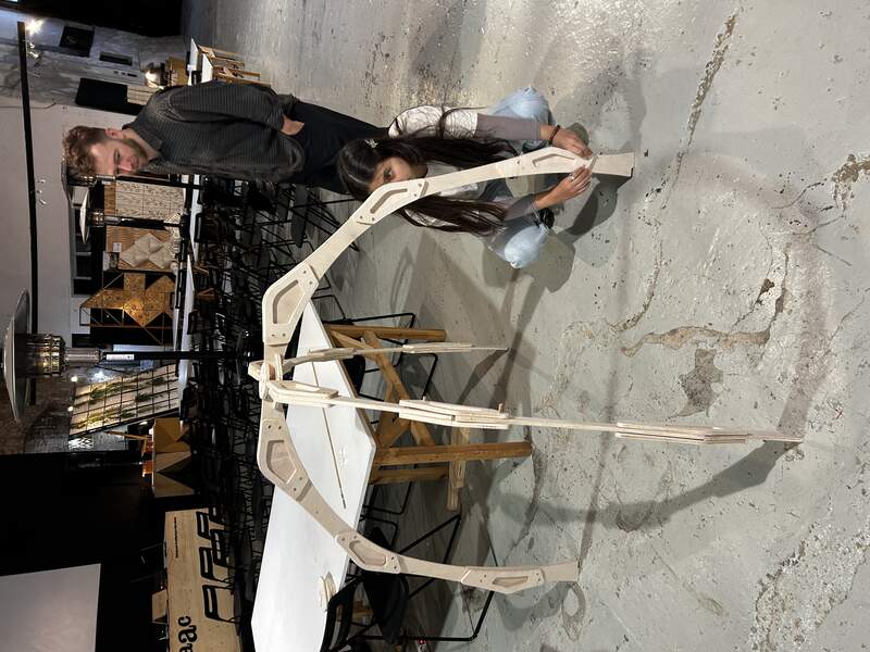
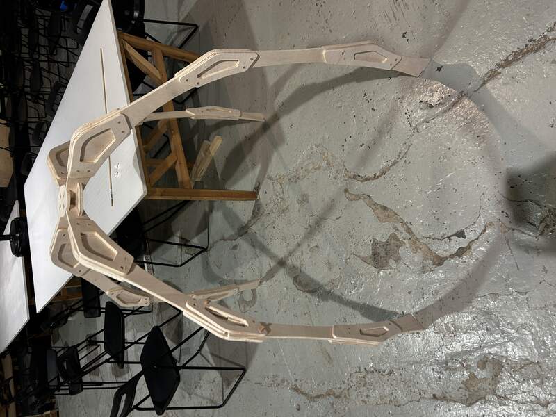
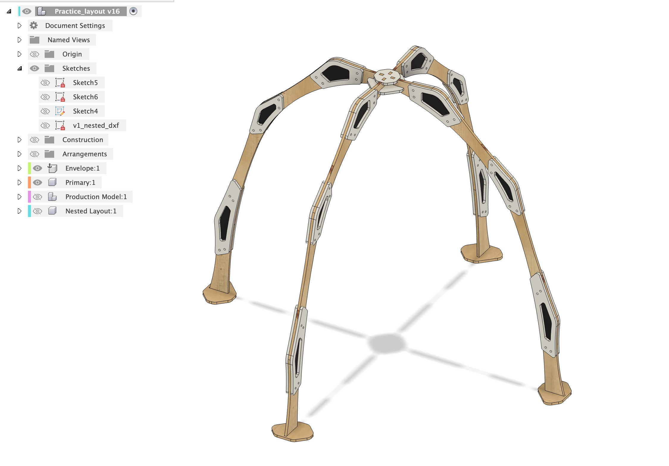
I wanted to create a structure as large as possible with the material I was given. I settled on a dome because its something I have never designed before and I figured it would be an interesting challenge. Aside from this I wanted the final design to be organic. Since the arc sub-assembly is repeated 4 times this allows me to explore the form quite a bit without compromising the stability of the design.
Was it successful?
I am considering using this in my final project so it creates an enclosed space around the work. However, I am not sure visually this is the direction I want to go with my final project. Technically speaking the design had some major hurdles to overcome. The cut quality was very bad. Most likely because I let the software choose a mix of climb and conventional cutting. For this reason I spent a total of 6 hours in post processing and assembly. Similarly, I had considered, but greatly underestimated the potential for misalignment of the dowel holes on the bracing pieces. This was an ambitious thing to try to do on a first draft so I was not too surprised these needed to be re-drilled.
- CAD modeling — I won’t go into too much detail about the CAD modeling, but here is a quick outline of the process. I needed to work out an arc sub assembly that I liked visually and could be broken up into pieces. By breaking it up into pieces I was insuring that I could get good yield of the stock in the nesting process. Below is the general order of operations.
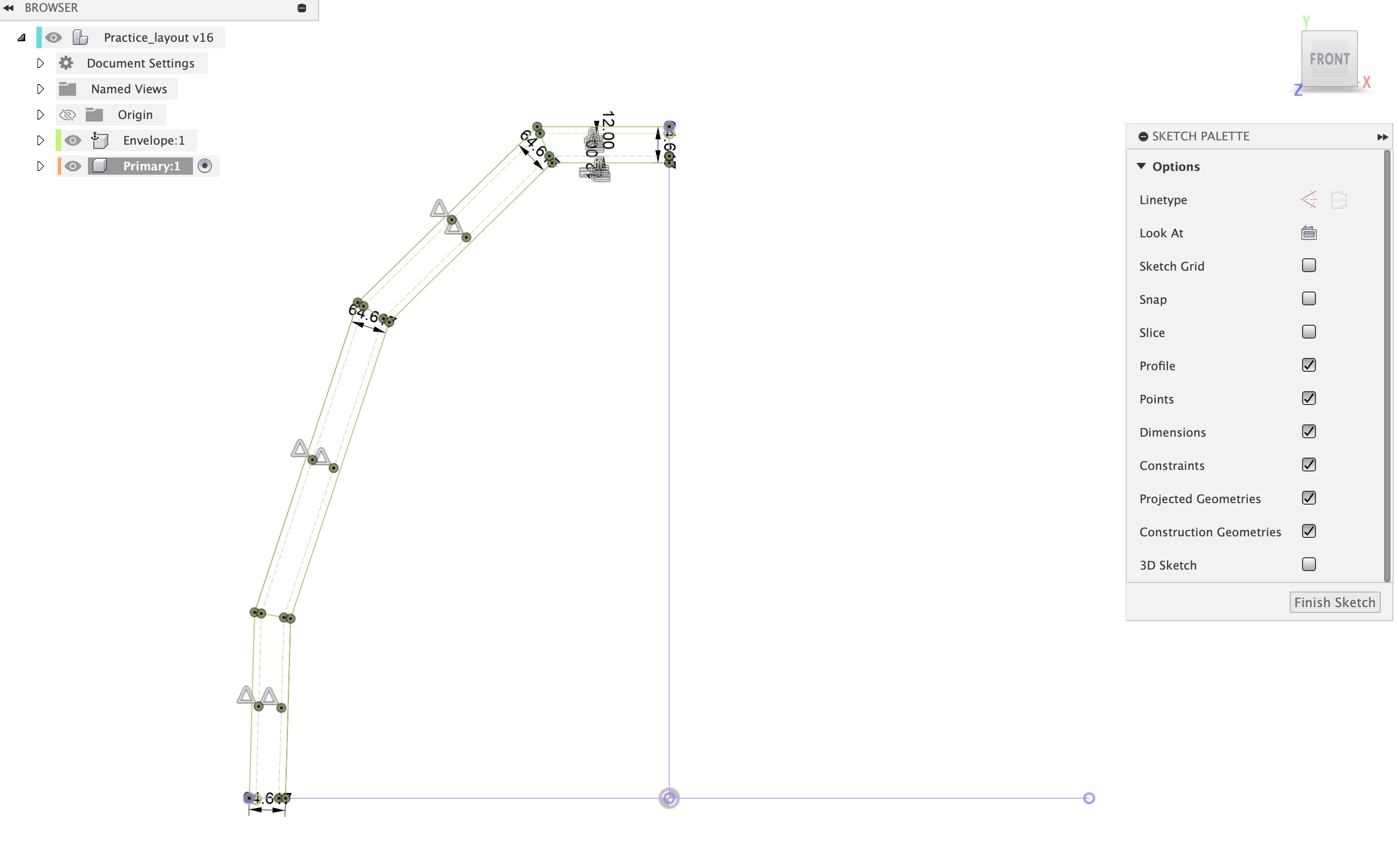
- I mocked up a few constrained lined sketches using the minimum width of the strut I thought would work [65mm].
- After I had a sketch geometry I liked I decided that the simplest and most reliable way to join the strut pieces was to brace them on either side.
- From here I went sorta nuts with the shapes and the joints. Trying to get something that had some sense of visual cohesion or rhythm by repeating module sizes and angles. About midway through the design process it had occurred to me that the design would already have this kind of visual cohesion because their are 4 identical copies of the half arch sub assembly in the design.
- CAD for CAM
- Adjusting fit— here I use a mixture of offset face and offset sketch commands. Offset sketch tends to be less compute intensive and maybe a bit less prone to user error because it is harder to accidentally miss a zone that needs to be offset. However, I tend to prefer the offset face command because it is easy to visually distinguish this action so I can confirm later that all key faces have been adjusted before the file is brought into CAM. This makes it easier to adjust and confirm this value later if I need more or less clearance. Since I had a lot of joints I mostly used the offset sketch command for this design to save time. However I do regret this because the base ‘feet’ mortise offset was forgotten. If I start doing a lot of CNC again I will develop a far more descriptive step by step workflow for this.
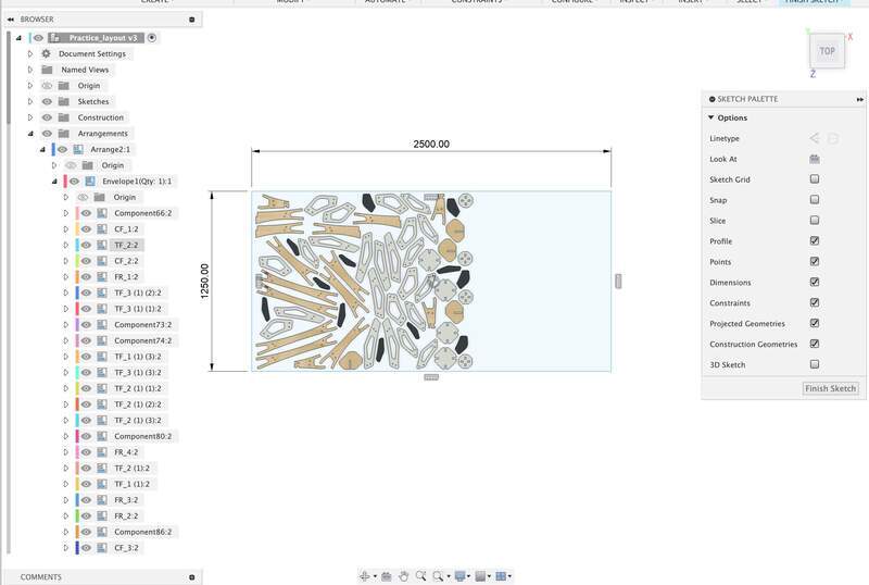
- Arrange in Fusion — is now very stable and very powerful compared to when I used it last. It enables you to create a full production model out of the nest which can be edited within the primary working design. I still think it is good practice to create a copy of the initial CAD specifically for production, but this time around I was curious if I could get away with skipping this step. Below is my current workflow for using the arrange feature.
- Create your stock profile as a sketch in the project layer not the component layers.
- Convert all bodies into components
- Open arrange and add your stock profile sketch and the design components you want nested.
- Create a new sketch in the project layer and project the arrangement.
- Rhino CAM
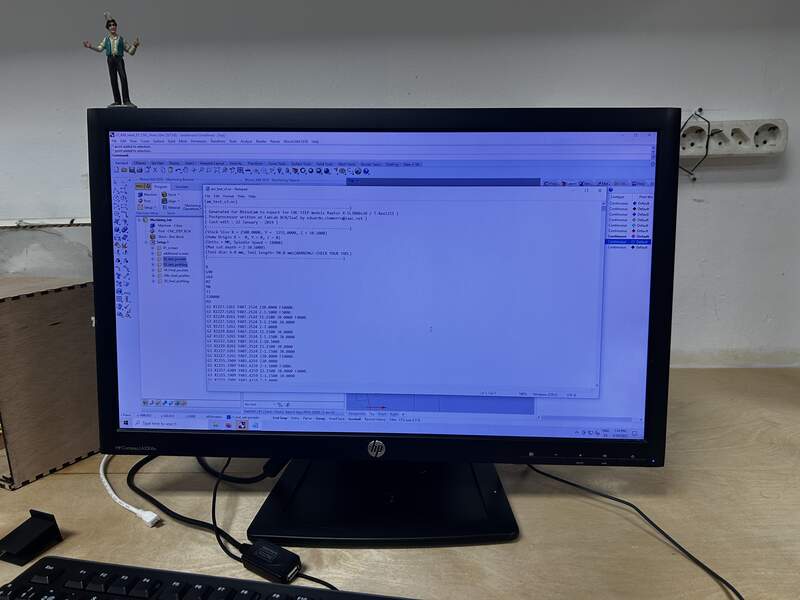
- I imported my nested DXF from Fusion into Rhino CAM using
import
- From here I moved into layers what I thought were geometry that needed to be separate machining operations into separate layers. My instructor Dani helped me a lot in this process and this required 3 cut test on the machine to insure correct settings were chosen. Again the design was fairly complex so it took time to make sure things were appropriately fixtured and machining operations were set appropriately for the various component feature in the design.
- Set stock variables
- Set all of the settings for the end mill you are using
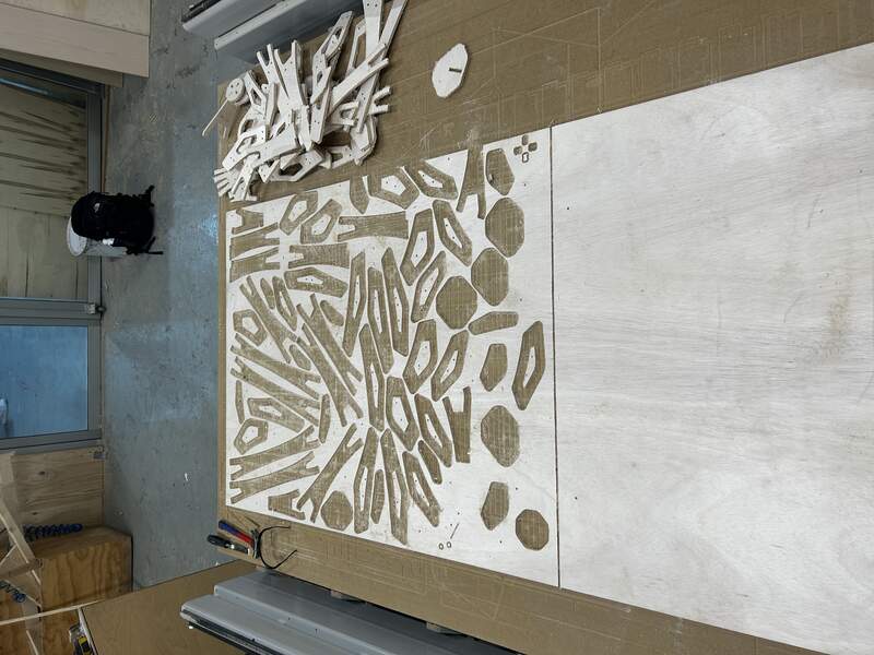
- All core settings were determined from our in class test and are listed earlier in this document. A mix of conventional and climb cutting was set (unfortunately) used. How the machining operations are broken up can be seen in the photo above.
- I imported my nested DXF from Fusion into Rhino CAM using
- CNC Machining
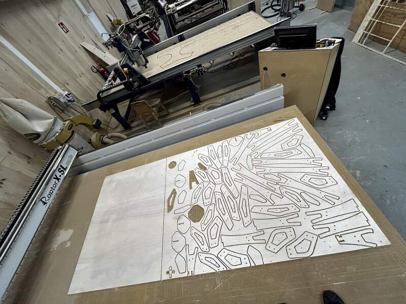
- Board was placed on CNC bed cupping side down.
- The Screws engraving Gcode file was loaded into the CNC control software.
- Tool was installed into the collet and collet was screwed into the spindle and tightened. We used a downcut bit for all of the machining. It is not ideal to use a single bit for all machining operation but it saves a lot of time and complexity. I was worried about how long the routing would take so in the case of this project machining time, and not even post processing time was a primary concern.
- Spindle was zeroed to corner of board on x, y and z
- Screw program was run
- I drove all screws… like 80 through the stock to the CNC bed
- Test pieces were cut. Me and Dani noticed that the pockets were cut too wide because the cut side of the the geometry was not configured. This meant that it was cutting on the outside of the pocket line and not the inside.
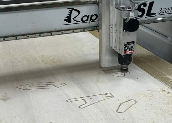
- Back to CAM we made the adjustments to the geometry and changed some profiling commands that needed to be pocketing commands.
- Post processing
- The machining was done very fast the whole program only took 1 hr to run. However the quality of the cuts were very bad. This was the result of a lot of choices. I thing ultimately it was my choice of using a combination of climb and conventional cutting. I had thought the program was using some kind of intelligent algorithm to determine which to use, but in reality it was just using the mix to decrease machining time. This left a very rough Finish on the parts that needed to be sanded.
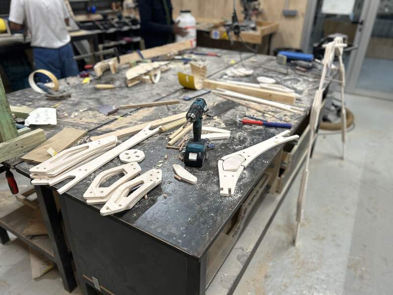
- Edges were sanded using a large standalone belt sander and inside edges were sanded by hand. The softness of the wood made it particularly difficult to get a smooth finish on the parts. In total this took about 5/ 6 hours over two days.
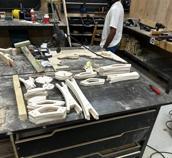
- Next parts needed to be joined with dowels. Dowel alignment was a big issue because of the amount of contacting faces. This is something I knew would be an issue, but I did not know to what extent. All holes thus needed to be redrilled. During this process our cordless Makita drill happened to have been on its last 15 minutes of life and released all of its magic smoke while I was using it.
- The machining was done very fast the whole program only took 1 hr to run. However the quality of the cuts were very bad. This was the result of a lot of choices. I thing ultimately it was my choice of using a combination of climb and conventional cutting. I had thought the program was using some kind of intelligent algorithm to determine which to use, but in reality it was just using the mix to decrease machining time. This left a very rough Finish on the parts that needed to be sanded.
04— Fusion CAM on the One-Step NC Raptor
I didn’t have time to work through this process, but I have successfully configured fusion CAM to work with 3rd party CNC routers. Our raptor CNC router uses One-Step control software. Luckily Fusion has an official post processor available for this machine. I did not get around to configuring my fusion CAM to work with the IAAC machines, but below is part of the workflow.
- Custom post processor needs to be installed in Fusion manufacture workspace.
- The specific machine limitations need to be configured here as well. At this point I could not remember how to configure things like its global coordinates and spindle limitations, I remember it being straightforward if you just locate the dialog.
- Everything needs to be tested with the spindle at a safe height to ensure proper configuration/translation of the CAM file.
Project Files
