05—3D Scanning and Printing
Assignment
3D Scanning and Printing
- Group assignment:
- Test the design rules for your 3D printer(s)
- Document your work on the group work page and reflect on your individual page what you learned about characteristics of your printer(s)
- Individual assignment:
- Design and 3D print an object (small, few cm3, limited by printer time) that could not be easily made subtractively
- 3D scan an object (and optionally print it)
Outline
- 00— Reflection
- 01— Group Project + Reflection
- 02— Quick Notes on 3D Printing Considerations
- 03— 3D Printable Design (Basin / Three Test Stand)
- 04— The 3D Printed Parts
- 05— Scanner Basics
- Project Files
00— Reflection
I am ultimately pretty happy with the test stand design. I designed this using modeling approaches I am pretty comfortable with while learning how to use the emboss tool which saved a lot of time routing the tubing. I am trying to not become too invested in this one idea so creating the test model frees me to explore the concept a bit more and figure out whether its possible or even interesting.
As I mentioned below I don’t typically draw much anymore and really have always seen drawing as a means to an end. I don’t like drawing and I am usually impatient to just test the project out. This is something I go back and forth on though I think in this case just modeling it makes sense, but with bigger projects I have probably wasted time avoiding creating a detailed initial plan on paper first.
Things I want to improve shiny things / improving my work — I really enjoy looking into new tools and in general learning something new. That said I have strong impulse toward complete-ism as in how Adam Savage describes it in his book, Every Tools A Hammer . Basically I am not a perfectionist, but a completionism, I want to go from top to bottom and address all of the details along the way or like look through the entire catalog of a tool website so I know every kind of battery powered tool you can conceivably buy off the internet. Basically I am hunting for context, but at a certain point I have to stop myself… because the internet is well… infinite.
So for me there is this constant tension of how to spend my time between tool-knowledge / skill acquisition / and producing work. I know several highly dynamic creative people in my life that create a large variety of work, but in the end the work doesn’t create a cohesive whole nor does a project get explored to the depth or pushed to the level of refinement it probably could have. This is something I have started to think a lot about with the work I am planning. Really the thought process came from watching the Olufur Eliason mini doc from Netflix’s series Abstract. In it he talks about his dad as this very dynamic comic and creative person that explored a lot of mediums, but wasn’t quite able to create much work that stood up on its own. To me Olafur Eliasson actually is able walk this fine line. His work is both cohesive and varied.
So… I would say this question of how and what to spend my creative energy on isn’t so much a question that can be answered as it is a knot I that I am constantly trying to loosen.
01— Group Project + Reflection
The Group Project produced two high quality prints. The X1 prints were very good except for some user error like not choosing a bad print orientation and leaving the supports on for too long. Once again I was reminded that I can be pretty aggressive with the geometry I create for 3D printing as the Bambu X1 does pretty well with things like bridging and tree supports cut down on support material usage a lot. The Elegoo print also turned out quite well. Seeing the workflow for the 3D scanners was insightful because it gave me an idea of where the technology is currently at.
02— Quick notes on 3D printing considerations
- Recently I had to print for 170+ hrs on my personal printer for a work project and since the components were structural I needed to compromise over strength and print time. I now use Bambu’s high strength part recommendation as my local maximum for tuning part settings. This setting is 6 Wall loops and 25% infill density). For this project I used 3 walls at 15% infill.
- From trial and error specifically on the Bambu X1 I use .15mm → .2m per side clearance for almost all my mating fits.
- Unless I have a reason not to, I have found the trees setting for support material in Bambu slicer to be far superior than regular supports. I only use regular supports if time is a real consideration or the geometry is special in some way.
- I really like a matte finish on printed parts and almost exclusively use PolyTerra Matte Muted White and have been searching for something that is also easy to print produces the same surface finish and has better heat tolerance to PLA.
03—3D Printable Design (Basin / Three Test Stand)
Section Summary: For my test model this week I decided to develop a test stand for my final project which would let me experiment with the dropper concept.
About the Design
Below are some of the requirements I had in my head when designing the project:
- I wanted to understand how to create a nice integrated form that drew inspiration from some of the reference photos I collected. This means figuring out how to actually model this form.
- It needed to enable me to test several things: dropper height adjustment, adaptability for different pump or dropper configurations, ability to experiment with light placement to crate caustic effects (underneath or above glass plate).
- Just by creating the CAD model itself I wanted to understand what issue were most prescient to solve in the design of the assembly. As an example, routing the silicone tubes in a nice way without pinching them was much more of an issue on the modeling and styling side than I originally expected. For example trying to predict how much slack the tubing needed and channel size it fits into was near impossible without a test model.
Design decisions for 3D printing
- Clearance fits — The test stand needs to fit together and certain joints like the moving platform need to be low friction—ish. So the most important consideration is that the clearance fits are actually clearance fits. The allowance for these parts is between .15mm to .2mm per side. In some special scenarios like the fit for the 2020 extrusion I have used slightly more clearance and have removed additional geometry like tight corners that could create unwanted binding. In the past I have found when when many mating surfaces are present there is greater potential for the joint binding.
- Support Material— In both the V1 and V2 CAD models I am considering the size of the pieces and where supports might need to be as well. So In this respect, I tried to avoid really significant overhangs to cut down on support material. That said, surface finish is not a something I care about at this stage so I did not worry about fillets and chamfers on the z-plane and blemishes from removed support material. Ultimately, I just wanted to design something that wasted a minimum amount of material while meeting the requirements I mentioned in the About The Design section.
- Rigidity / Material wastage — I wanted the design to be rigid and not tip over so extended the footer pretty far out. I also added more holes than probably needed [4] for the top plate clamping assembly, just in case. Similarly, the motor in the back was placed to counter balance the water weight in the top tray. Mostly though, I just tried to use my best judgement + a little extra, adding material in areas that seemed important. The chamfers and fillets are aesthetic, but I also used them to slim down the model where material wasn’t needed. Ultimately, one of the most significant decisions for strength is to increase the perimeter count from 2→3.
3D Modeling + Design Ideation Process
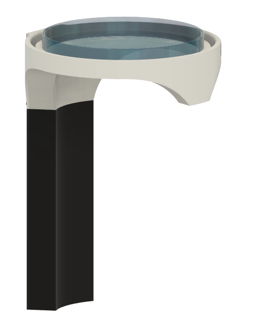
- Sketching in CAD V1— By starting first in CAD this lets me get a feel for the constraints of the design in realtime. Similarly, the CAD tool itself constrains the options I have to style it visually which constricts my options as a designer usually for the better. Below is what I would call a ‘CAD sketch’ here I am just trying to make the model as quickly as possible. In this first model I was mostly interested in exploring how to mimic this shape (below left). Naturally, the down side to creating CAD quickly is that the model is a bit of a hot mess to work with after it is finished, but if its made fast I should have time left to remake it (at least thats what I tell myself ;) ).
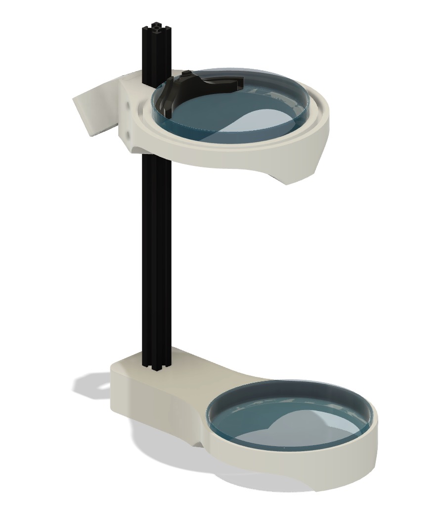
- Sketching in CAD V2. After I designed the first version I decided 3D printing the mounting column was not a good design choice... in pretty much every way. I decided it was worth it to redesign the model around 2020 aluminum extrusion as the column. Using 2020 extrusion enabled more testing scenarios and decreased 3D printed part count/time.
04—The 3D Printed Parts
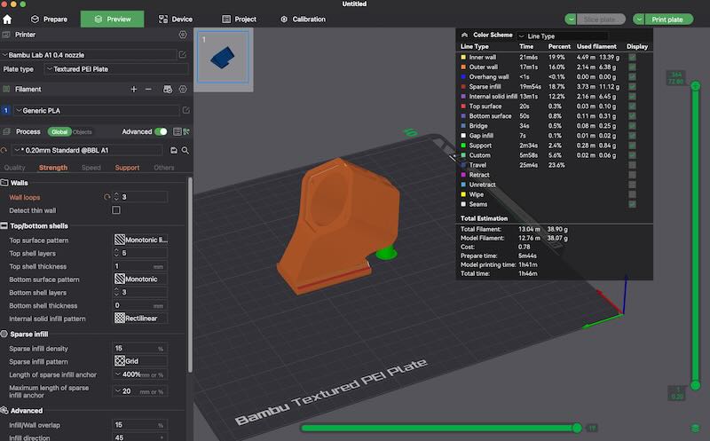
- Print Settings— Below are the settings I used for the final part.
- Print preset
.20mm Standard Settings…used
- Changed
Wall loops[3]
Tree supports[x]
- Print preset
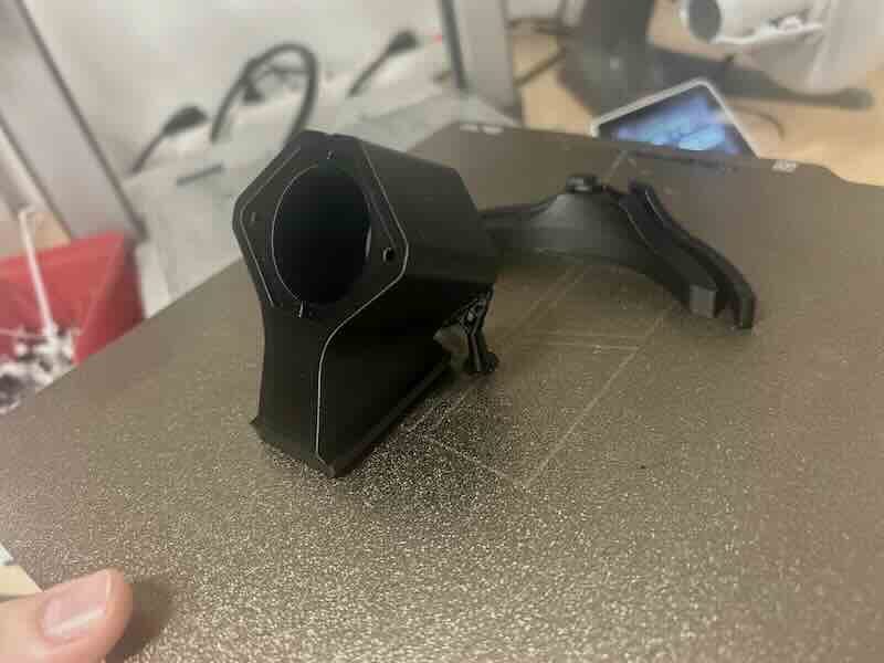
- Print Analysis— The parts came out well enough for my needs.
- I didn’t use glue stick or clean the print plate before printing so the bottom on one part had some minor first layer adhesion issues.
- I designed the part around an official CAD model I found, before I received the DFR peristaltic pump which was slightly off so the pump mounting plate didn’t fit the way I had hoped but was still usable.
- I haven’t tested the sliding joint yet for the pump carrier mount which is likely that might also need some adjusting.
- I probably could have dropped the perimeter count from 3→2. I usually print in PolyTerra PLA Matte which I think is slightly weaker than regular PLA because of the additives. Either way the parts ended up being stronger than needed.
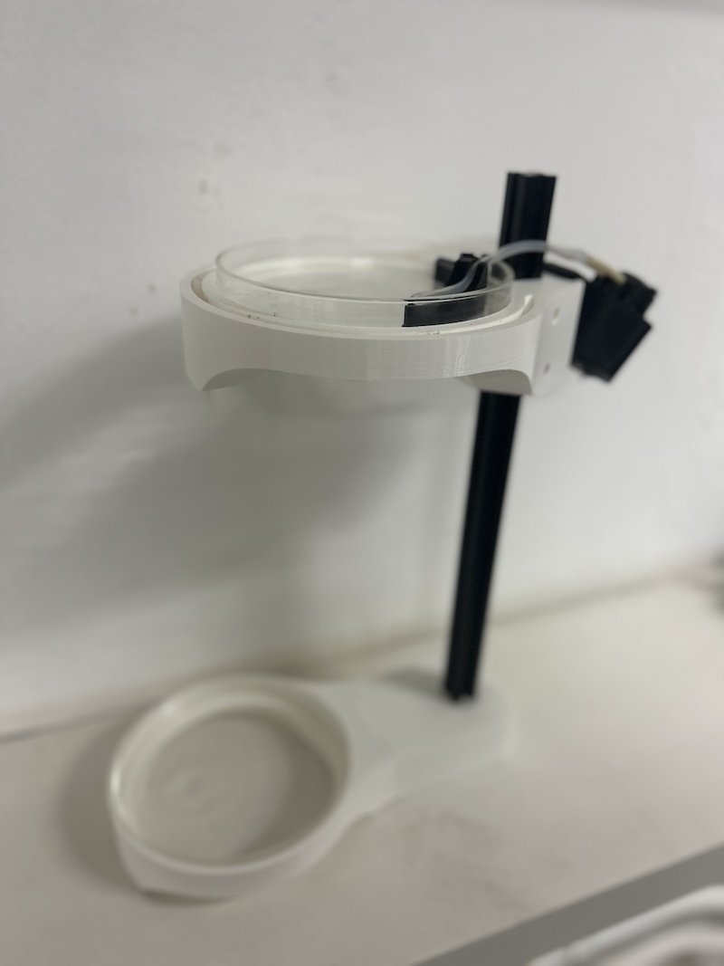
- Full finished assembly w/ white prints — The rest of the prints were printed on the Bambu X1 Carbon with the settings change of 2 wall loops instead of 3.
05—Scanner Basics
Scanning it seems is still in an awkward space. It has gotten pretty good, but the technology hasn’t fully matured. I avoid working with meshes like the plague so this might also be why I haven’t been that interested in scanning generally. I think its use for something like AR or augmenting physical controls is the most interesting use case for me. Below is one of the photos for class.
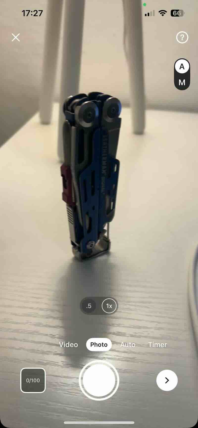
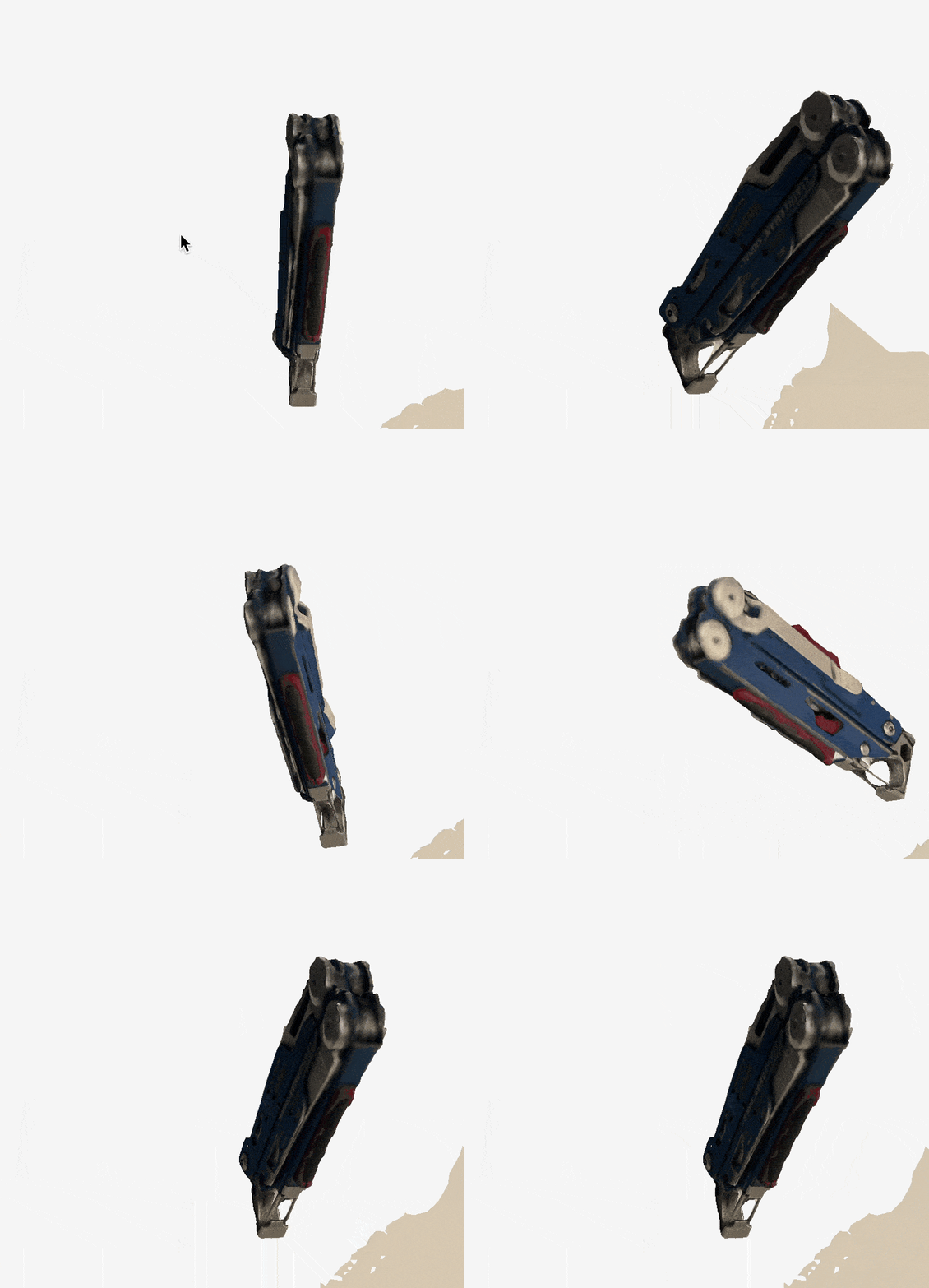
- I went with photogrammetry because I wanted to see what kind of result I could get with just my iPhone (no lidar). I scanned my Leatherman multi tool because it is an object with a lot of complexity/patina/texturing. I went with the software Kiri from the iOS app store which was highly rated.
- The software was very intuitive and prompted me to take a 100 photos of the object which seamed like a significant amount of data to train on. I tried to light the object uniformly and place it near my lamp for better uniform lighting. Its just their free version and I am betting you could get a better version out of the pro as it enables more pictures. I would say the results I got were comparable to the 1st generation Kinect when you remove the textures the model has got some issues, but all in all I am pretty impressed.
Design Files
