04—Embedded Programming
Asignment
- Group assignment:
- Demonstrate and compare the toolchains and development workflows for available embedded architectures
- Document your work to the group work page and reflect on your individual page what you learned
- Individual assignment:
- Browse through the datasheet for your microcontroller
- Write a program for a microcontroller, and simulate its operation, to interact (with local input &/or output devices) and communicate (with remote wired or wireless connection)
Outline
- 00 — Thoughts on Learning and Programing
- 01 — Group Asignment Reflection and Link
- 02— Sifting Through Example Program
- 03— Essential Arduino Context and Syntax
- 04— Writing Code for the Barduino
- 05— Basic Program of My Own
- 06— Switching over to the Xiao Platform
- 07—ESP32 -C3 Datasheet
- 08—Final Project Software Needs
- Citations
- Project Files
00 — Thoughts on Learning and Programing
This week was challenging in terms of prioritization. I found myself wanting to go deeper with the coding and than going slightly too deep and getting lost. I tried to avoid using chat GPT as much as possible and to try and figure what was going on by reading the arduino official documentation. So that said it was very much a bootstrapping process for me. Programming has so many interlinked and dependant concepts that I feel like you just have to jump into the center of it and climb your way out. The trick was trying to pick things to work on that didn’t get me too lost.
01 — Group Asignment Reflection and Link
Reflection:
While I think it is incitful to learn how to get an MCU chip up and runnining from scratch the only context I think I would want to use this is hardware hacking. I know in the context of power tool batteries and scientific calculators I have come across projects that require reflashing chips. Ultimately though, since I plan to develop around small dev boards because I would never scale a personal electronics project into a full fledged product on my own I will be sticking with the XIAOs.
I do find the compiling times that the ESP32 boards take to be a bit annoying so when possible I might use the SAMD21 flavor of the XIAO. As far as programming goes once I am more comfortable with the basics of coding in arduino’s flavor of C++ I might look into circuit python mostly because I think knowing a little python could be useful.
02— Sifting through an example program
- Working through all functions in the program I copied from class. I simulated an arduino and ran the code code in TinkerCAD circuits.
int numberExecutions = 0;

void setup() // interesting there is a delay and print in the setup I guess you can put anything in setup as long as it only needs to run once
{
  Serial.begin(115200); // sets baud rate or bit rate the console reads at
  pinMode
  Serial.println("Morning!"); // Message at initialization
  delay(1000); // delay before start program
}

void loop()
{
  Serial.print("Hey "); // this print variation apears to just be for ASCII
  String name = "Andrew "; // stores an ASCII text label to the string
  delay(1000); // time callout here asumes ms

  Serial.println(name);// this refferences the string,
  //serial println finishes the line whereas serial.print just puts the label on the current lin

  delay(1000);

  float temperature = 23.3; // this denotes temperature as a floating point number which is a non integer number that can be recorded to a high resolution
  int kelvins = temperature + 273; // int (integer) specifies the new variable kelvins to be displayed in whole numbers and = temperature + a value

  Serial.print("It's ");
  Serial.print(kelvins);
  Serial.println(" K degrees out there ;):");


  delay(500);
  float time = millis();
  Serial.print("Its been ");
  Serial.print(time / 1000);
  Serial.println(" seconds since bootup");

  //Number of executions is 4

  Serial.print("I've run ");
  Serial.print(numberExecutions);
  Serial.println(" times!");

}
Variables Used
Var. type Var. Name Value string name Andrew float time millis() int kelvins temperature + 273 float temperature 23.3 int numberExecutions 0
- Kept on editing the above code until I fixed all of the errors from my initial hand typed copy from class. I worked line by line consulting the online Arduino code documentation when needed and Dani’s HackMD webpage. I added some explanatory comments as I went through by using
//. Things like missing“and;were primary issues that were causing compilation issues. Could not remember how to fix numberExecutions counter and decided to focus on understanding and get comfortable writing the core syntax.
03 — Essential Arduino Concepts and Syntax
About Section: This is a section I just updated continually throughout the whole process detailed on this page.
const intsets an imutable variable (often used for pin asignment) that cannot be changed and should be used over just int (changeable) and #define (which is supposedly hard to debug)
#define pin_name 2(note no semi colon and that this is used before setup() ) the define function is more like a find and replace that replaces that name with the pin number during compilation. This uses less memory than the int callout approach.
int pin_name = 46;this is how you give a pin a name and happens before void setup()
Serial.print("something to print")= anything printed to the serial on the given line— it will just keep on printing to the right… forever until you finish the serial print line.
Serial.println("something to print")= something printing in the terminal that will ocuppy and finish the line.
+ - * /all arithmetic operator behave as you would expect.
delay()full program stop for duration set in ms
millis()is like a stop watch you can call upon to tell you how long it has been since the arduino began running the loaded program.
- Function → Think of it as a single hanging folder in a filing cabinet drawer. The drawer will have a name (program name) and the folders will also have their own names (variable name). Important to note is the
=sign is an asignment operator and does not signify equivalence like==does.- Data types
int= denotes an integer or whole number value- ex.
intresultasint = 4.3+4.3
- ex.
float= gives you a floating point value- ex.
floatResultAsFloat = 4.3+4.3- would return 8.6
- ex.
boolean=- ex.
boolean
- ex.
String
- ex.
- Comparison Operators (boolean)
>=greater than or equal to
<=less than or equal to
==equal to
!=not equal to
>greater than
<less than
- The big three control structures—used either by themselves or in combination. They are what they sound like.
- Sequential
- Executes instruction in a linear order
- Selection
- Single Branch — do this if condition is met
if (expression) {
  statement;
}
- Dual Branch — do this if condition is met → if its not though do this other thing
if (expression) {
  statement1;
}
else {
  statement2;
}
- Multi Branch — do this if statement 1 is met → otherwise do this if statement to is met → otherwise do this if statement 3 is met
if (expression1) {
  statement1;
}
else if (expression2) {
  statement2;
}
else if (expression3) {
  statement3;
}
- Single Branch — do this if condition is met
- Loops — useful if you need to constantly check for update to a value like realtime temperature data. There is a mandatory loop in arduino code
loop() []. Curious what the syntax is to embeded loops within the loops.
- Sequential
-
buttonState
- MCU I/O
digitalWrite(pin, value)value can be HIGH or low or maybe a number also? This would for example set an output (like an LED) atatched to a pin to its full on or off state.
value = digitalRead(pin)not sure how flexible the value (class?) is, but this would be for reading something that samples an input like temperature.
pinMode(pin_variable, OUTPUT)is declared in setup to configure the pin.
- Built in Functions
tone(buzzer_pin, frequency, duration)enable quick configuration of a simple speaker to generate a tone
int value = touchRead(touchPin);
04—Writing Code for the Barduino
- Adapting original code to control core capabilities of the barduino: LED, RGB light, buzzer.

- Getting it onto the Barduino → from class installing the board library into the arduino IDE.
This link provides all of the steps needed to configure the board with Arduino IDE.
- This happeded to me “!!! bug The first time you connect your board it may connect and disconnect, once you program it, it will show as connected.”
- Program upload issue? Reset the board by putting it into boot mode! Reset Button + Boot button then release Boot Button. This will stop any code running into the ESP32S3 making it available for programming at any time. Once you upload the code it will not run automaticaly, please reset your board in normal mode again.
- I decided to add in the buzzer command to the original code. I just consulted some of the arduino code examples to figure out how to set the pin output. Also wanted to figure out how to give pin 46 a variable name. Figured this out through reading this example code . I now realize that the pin is declared outside of the void setup and it uses
intwhich seems a little superulous because a pin would alway be an int. Similarly it is interesting it defualts to intrepreting the number callout as a pin. I am unclear what things should and should not be declared beforevoid setup().int buzzer_pin = 46; void setup() { pinMode(buzzer_pin,OUTPUT); } void loop() { tone(buzzer_pin,400,250); delay(2000); }
- Flashing external LED 48. Similiar code to buzzer. I wonder if I were to use a sensor the pinmode callout would be INPUT.
int LED_BUILTIN_48 = 48;

void setup() {
  pinMode(LED_BUILTIN, OUTPUT);
}

void loop()
{
 digitalWrite(48, HIGH);
 delay(1000);
 digitalWrite(48,LOW);
 delay(1000);
}
- RGB pulse different colors. Looking at the example code provided on the Barduino page. It is clear that a library is needed so I went ahead and installed that by going into arduino IDE then searched the package name then install. I addded comments inline with the code to workthrough what was going on. I quickly looked at the function section in the library page, but decided not to introduce learning the functions of the library this weekend because I still dont fully understand the basics of the arduino language. In a general way from the original comments I see what they do.
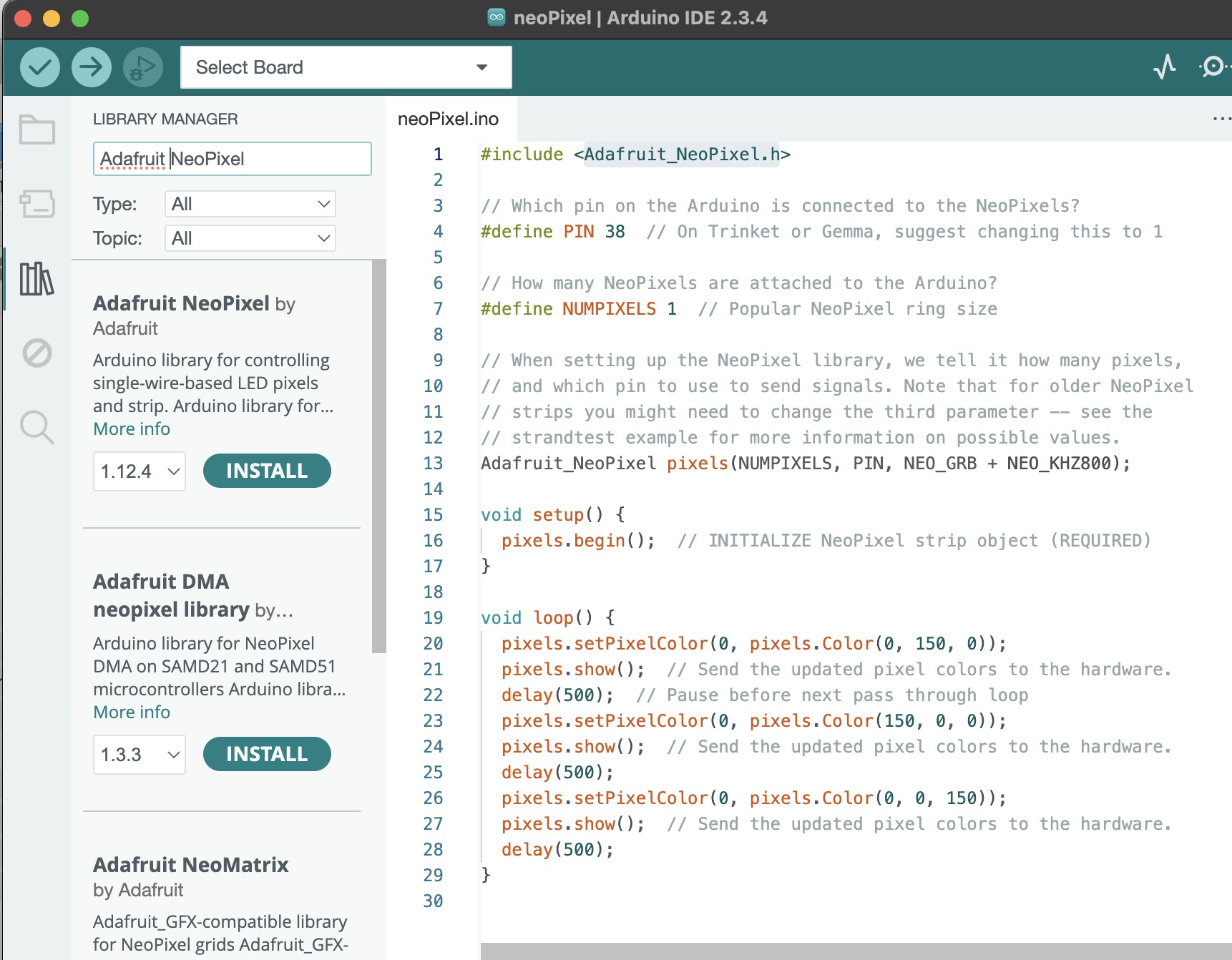
#include <Adafruit_NeoPixel.h>  // calling upon the library is done before setup function

#define PIN 38  // do not know what define does

#define NUMPIXELS 1  // this is how many pixels you have being one NUMPIXEL I asume is a variable

// When setting up the NeoPixel library, we tell it how many pixels,
// and which pin to use to send signals. Note that for older NeoPixel
// strips you might need to change the third parameter -- see the
// strandtest example for more information on possible values.
Adafruit_NeoPixel pixels(NUMPIXELS, PIN, NEO_GRB + NEO_KHZ800);

void setup() {
  pixels.begin();  // INITIALIZE NeoPixel strip object (REQUIRED)
}

void loop() {
  pixels.setPixelColor(0, pixels.Color(0, 150, 0)); // dont understand what the first 0 does but I asume 0, 150, 0 are RGB.
  pixels.show();  // Send the updated pixel colors to the hardware. Not sure why this would not be part of the last function
  delay(500);  // Pause before next pass through loop
  pixels.setPixelColor(0, pixels.Color(150, 0, 0));
  pixels.show();  // Send the updated pixel colors to the hardware.
  delay(500);
  pixels.setPixelColor(0, pixels.Color(0, 0, 150));
  pixels.show();  // Send the updated pixel colors to the hardware.
  delay(500);
}
- Print simple serial data into console when capacitive buttons are pressed.
Barduino example code
void setup() {
  Serial.begin(115200);
}

void loop() {
  int touch = touchRead(4);//its only printing for touch pad 4 it reads an integer value and its using a built in function 'touchRead' which is acting on pin 4 it is specifically built for the esp boards and in this case the touch sensor is capacitive
  Serial.println(touch);
  delay(500);
}
Resulting errors after running code on Barduino
I received a bunch of numbers as a response my asumption after looking at the touchRead implmentation on other websites from a simple google search I noticed that there was more interpretation of the input going on. So educated guess was it was just reading and printing the values that the capacitive touch sensors were reading.
Chat GPT “touchRead fucntion in arduino” — yes it was mispelled. I decided to prompt chat GPT to generate the code this approach made a lot of sense to me … comments are mine.
const int touchPin = 4;
int threshold = 40000;  // Adjust based on your sensor's environment

void setup()
{
Serial.begin(115200);
}

void loop() {
  int touchValue = touchRead(4); // declaring the following as an integer value -> relating it to the built in function touch read and asigning touch read to the pin used on barduino for the touch input [4]
   Serial.println(touchValue);
  if (touchValue < threshold) { // threshold is declared earlier so I gues I will set this to a low positive reading.
    Serial.println("Touched!");
  }
  delay(100);
}
*Raw serial print data from previous code 22,700 (not touched) → >40,000 (when touched)
*Chat GPT code suggested excluded void setup() weird… I learned this needs to always be included.
*added in Serial.println(touchValue); to see if I could get anyhthing printed turns out chat gpt also excluded initializing serial communication in setup.
- Frankenstein’d touch button and neo pixel code to trigger neo pixel when touch04 is activated. I wanted to test if my intuition about selection tree(?) was correct so I coded the tree based on my notes and had no Idea if it was going to work.
const int touch_1 = 4;
int threshold = 40000;  // Adjust based on your sensor's environment

#include <Adafruit_NeoPixel.h>  // calling upon the library is done before setup function
#define PIN 38  // do not know what define does=
#define NUMPIXELS 1  // this is how many pixels you have being one NUMPIXEL I asume is a variable
Adafruit_NeoPixel pixels(NUMPIXELS, PIN, NEO_GRB + NEO_KHZ800);

void setup()
{   Serial.begin(115200);
    pixels.begin();  // INITIALIZE NeoPixel strip object (REQUIRED)
}

void loop() {
  int touchValue = touchRead(4);
   // declaring the following as an integer value -> relating it the built in function touch read and asigning touch read to the pin used on barduino for the touch input [4]
  if (threshold < touchValue) { // threshold is declared earlier so I gues I will set this to a low positive reading.
    Serial.println("Touched!");
    pixels.setPixelColor(0, pixels.Color(0, 150, 0)); // dont understand what the first 0 does but I asume 0, 150, 0 are RGB.
    pixels.show(); }
  else
    {pixels.setPixelColor(0, pixels.Color(0, 0, 0)); // dont understand what the first 0 does but I asume 0, 150, 0 are RGB.
    pixels.show(); }

  delay(100);
}
- Getting it onto the Barduino → from class installing the board library into the arduino IDE.
g. Getting raw data and serial printing from temperature sensor. Looked at sample code from Barduino and added Temperature_LM75_Derived.h to my arduino IDE. Comments are my own. Could not get this to work and decided this would take a lot of sleuthing to figure out why and decided to put my time elsewhere.
#include <Temperature_LM75_Derived.h>
#include<Wire.h>

TI_TMP102 temperature; //declaring an object named temperature from the class TI_TMP102 I am not sure how this works or why it is necarry at all.

void setup() {
  Serial.begin(115200);
  Wire.begin(); // chat gpt says that it initializes the i2c communication using the wire library I don't think it needs to be included but I included it anyway
}

void loop() {
  Serial.print("Temperature = ");
  Serial.print(temperature.readTemperatureC()); // asumming readTemperatureC is a library functin and could probably be changed to readTemperatureF read one of the git files and yes this is correct
  Serial.println(" C");

  delay(500);
}
*not too familiar with working with I2C from looking at the repo page for Wire.h it doesnlt look I need to tell I2C where to look because it should default to read from the right pins.
*Looking at the Repo page for Temperature_LM75_Derived.h I got a sense for what functions it includes particularly conversions to other common temperature units as I suspected.
05— Basic Program of my own
- Generates a tone and a color for each capacitive button. This was another mix of code I had already written.
#include <Adafruit_NeoPixel.h>  // calling upon the library is done before setup function
#define PIN 38  // do not know what define does=
#define NUMPIXELS 1  // this is how many pixels you have being one NUMPIXEL I asume is a variable
Adafruit_NeoPixel pixels(NUMPIXELS, PIN, NEO_GRB + NEO_KHZ800);

const int buzzer = 46;
const int tactile = 0;
const int touch1 = 6;
const int touch2 = 5;
const int touch3 = 4;
const int touch4 = 7;
int threshold = 40000;  // Adjust based on your sensor's environment


void setup()
{   Serial.begin(115200);
    pixels.begin();  // INITIALIZE NeoPixel strip object (REQUIRED)
}

void loop() {
  int touchValue = touchRead(touch1);
  int touchValue2 = touchRead(touch2);
  int touchValue3 = touchRead(touch3);
  int touchValue4 = touchRead(touch4);

  if (threshold < touchValue) {
    Serial.println("Touched 1! ");
    pixels.setPixelColor(0, pixels.Color(50, 0, 0));
    pixels.show();
     tone(buzzer, 200, 50); }

  else if (threshold < touchValue2) {
    Serial.println("Touched 2! ");
    pixels.setPixelColor(0, pixels.Color(0, 50, 0));
    pixels.show();
     tone(buzzer, 250, 50); }
  else if (threshold < touchValue3) {
    Serial.println("Touched 3! ");
    pixels.setPixelColor(0, pixels.Color(0, 0, 50));
    pixels.show();
     tone(buzzer, 300, 50); }
   else if (threshold < touchValue4) {
    Serial.println("Touched 4! ");
    pixels.setPixelColor(0, pixels.Color(50, 10, 50));
    pixels.show();
     tone(buzzer, 350, 50); }
  else
    {pixels.setPixelColor(0, pixels.Color(0, 0, 0));
    pixels.show(); }

  delay(100);

}
06— Switching over to Xiao Platform
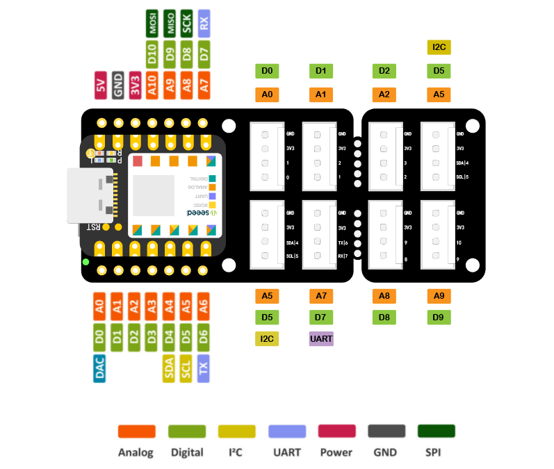
- I am planning to use the Xiao C3 as my development platform moving forward so I am going to be working using this development board and examples from this Xiao tutorial series relevant to my Final Project. In the spirit of spiral development the goal is to increment a servo at a rate set by a potentiometer. So potentiometer will be broken up into 8 discrete steps than the program will pulse the servo for a set duration at the rate defined by the pot.
- To start lets try to read a pot. Code taken from here notes are my own. I don’t fully understand why it needs to use the approach detailed below to read the POT. The guide was not very clear on this.. ok I think I got it. The pot full rotation is 300 degrees not 360. The ADC refference voltage would be the pot max I think in this scenario.
#define ROTARY_ANGLE_SENSOR A0
#define ADC_REF 3
#define GROVE_VCC 3
#define FULL_ANGLE 300

void setup()
{
    Serial.begin(9600);
    pinMode(ROTARY_ANGLE_SENSOR, INPUT); // setting rotary angle pin as input this variable is set to A0 in the define section above
}

void loop()
{
    float voltage;//strange that you are defining the variable type without an argument
    int sensorValue = analogRead(ROTARY_ANGLE_SENSOR);//Read the analog value at the rotary potentiometer pin
    voltage = (float)sensorValue*ADC_REF/1023;//Calculate real-time voltage
    float degrees = (voltage*FULL_ANGLE)/GROVE_VCC;//Calculate the rotation angle of the knob
    Serial.println("The angle between the mark and the starting position:");//Print characters at the serial port
    Serial.println(degrees);//Print the rotation angle value of the rotary potentiometer at the serial port
    delay(100);
}
- Decided to work with the original built in example from Arduino because it was eaiser for me to understand. Rewrote it and tested it in Tinker Circuits.
void setup(){
  Serial.begin(9600);

}

void loop(){
	int sensorValue = analogRead(A0);
	float voltage = sensorValue * (5 / 1023.0);
	Serial.println(voltage);
	}
*original code is for a standard arduino which has 10 bit DAC [1023] and a nominal V of 5V. The Xiao C3 is 3.3 V and has a 12 bit ADC [4095]. So basically the ADC can sample the Analog input at a resolution of 4095. Similarly I think I can increase the baud rate?
07— ESP32 C3 Data Sheet
Spent time goint through the ESP32 C3 datasheet because that is most likely what I will be programming on.
- Diagram of chip architecture
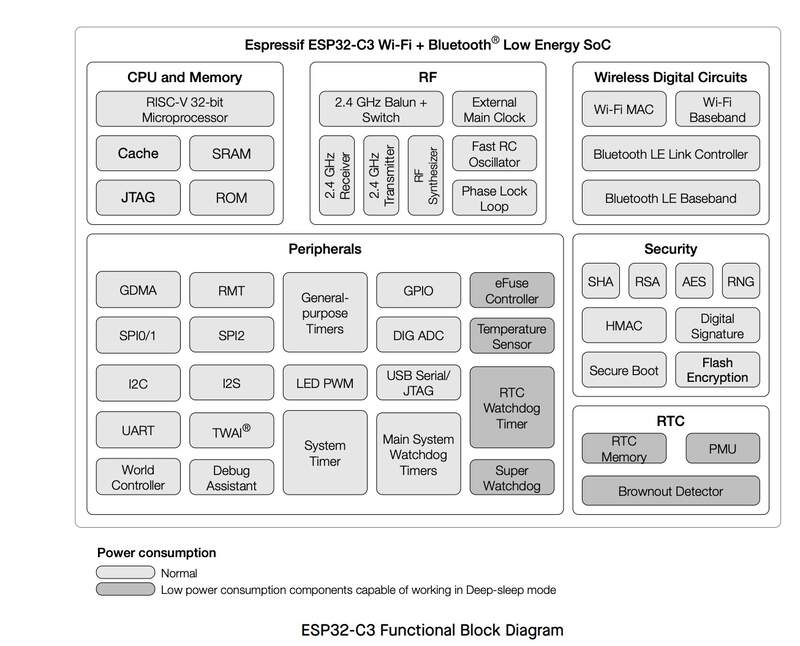
- Features that seamed relevant
- Bluetooth LE / Bluetooth 5
- Uses a 32-bit RISC V architecture can run at a clock speed of 160MHz
- 22 or 16 programmable GPIOs
- Three SPI, Two UART, I2C, I2S
- built in temperature sensor
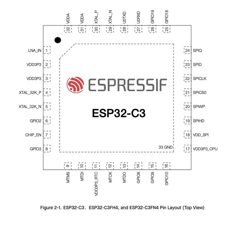
- Chip Pinout
08— Outlining final Project Software/Hardware needs
Quick breakdown of full control program
- I am using 3x MR60BHA2 heartbeat sensors each powered by a xiao C3. These will be hardwired to send their data over I2C to a master XIAO C3. Data sent should basically communicate: is there a person (yes/no) [loop every 2 seconds until condition is met] if yes → what is their heartrate → how much are they moving (low/medium/high) → what is their breathing rate.
- The master Xiao + expansion then interprets this simplified data. ie. is there a person in Seat1 (y/n) does their movement = low if conditions are met then take rate integer [drops / per beat] value set by external potentiometer and push to servo 1 control dosing program. This will then constantly update until heartbeats drop so low that it is unlikely their is a person still present say [40BPM] at which point it returns to back to the beginning of the program waiting for the condition to be met.
Citations
- When consulted use of Chat GPT is mentioned throughout and often questions were to clarify syntax rules with some direct questions to provide a use case and sample code.
Project Files
—All code is provided in text body
- Introduction to Xiao Ebook https://mjrovai.github.io/XIAO_Big_Power_Small_Board-ebook/chapter_1-2.html