03 — Computer Controlled Cutting
Asignment
Group assignment
- Characterize your lasercutter's focus, power, speed, rate, kerf, joint clearance and types.
- Document your work to the group work page and reflect on your individual page what you learned.
Individual assignments
- Design, lasercut, and document a parametric construction kit, accounting for the lasercutter kerf, which can be assembled in multiple ways.
- Cut something on the vinyl cutter.
01—Group Asignment
Group Asignment Reflection
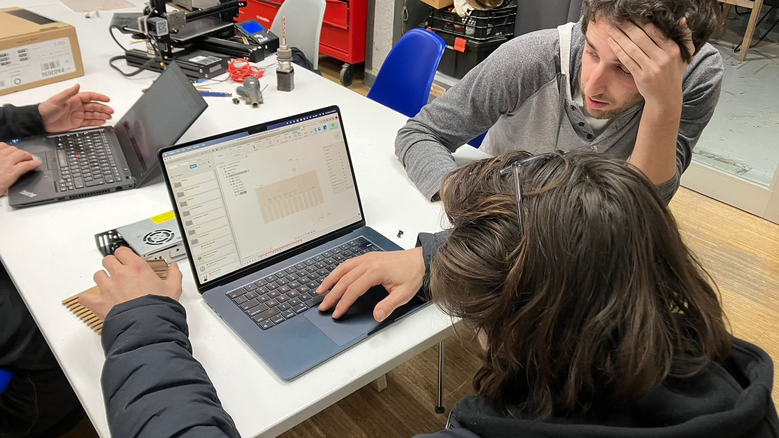
I used to work with a Kern 100W Industrial C02 Laser at my old work and got to put in a lot of hours in it. So along with work and personal projects I tried some experiments on it. Specifically I tried to calibrate it to blind joints to avoid CNC cutting at depth. Basically lasering out a cavity. This technically worked, but was pretty hard to calibrate.
That said, machine control software can vary a lot and it took us as a team about 2 hours two understand the laser’s control software and the 3D to 2D workflow IAAC uses for the laser. I did all of the parametric modeling with some feedback and design sugestions from the group and also tried to explain my process. We worked as a team to remember the steps needed in the Rhino import process and how to configure the settings on the laser. Similarly, many mistake were made in the configuration of the softwares and as a group we were to conservative with our kerf adjustment values on the first run through.
More details about the group asignment can be found here
02— Parametric Construction Kit
About The Design
- As I had said earlier I had experience with laser systems, and parametric workflows in fusion for laser cut projects, but I was anxious to get comfortable with the workflow of the specific machines at IAAC. I am always surprised at how much these machine control softwares vary even though all share very similiar functionalities. In my experience these softwares are universally pretty terrible and its too bad they don’t use the same hybrid approach 3D printers have taken where different brands utilize a vetted open source control software. That said, as much as I struggle with Rhino using it as a 3D to 2D pipeline made a lot of sense in this context. In the past I developed my own 3D to 2D workflow for Fusion at the shop I worked at and it involved a lot more steps between fusion→illustator→PDF etc. Now that I am learning more about scripting this probably would have been a more appropriate approach.
- Anyways… so because I wanted to just get a feel for workflow at IAAC and quirks of the machines as quickly as possible. I designed a very basic module based on a kind of dogbone profile for the modular piece. I figured it would be a good initial test to create the modular piece I needed for a laser cut mini ladder I wanted to make as an art project (details in later section).
Design Considerations
- For my design I planned to use the 4mm plywood provided in our course. Thus, I was able to leverage the values we generated for the (machine model) with the calibration comb we created for the same material. I liked the fit of the slot we created with a 1mm kerf offset so I used that value for an effective slot width of 3.07mm in my design workspace.
- Below is a quick step by step of the CAD workflow
- Defining parameters
- matthick
- kerfhalf
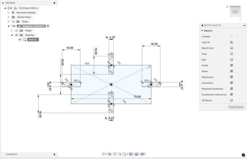
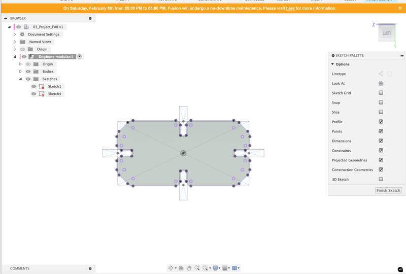
- Draw a sketch. It took me several iterations to understand how the bese way constrain the sketch. This is what I came up with after 3 tries. Its just a rectangle with the correctly sized slot cutaways. After the first iteration I had remembered to make sure that enough clearance was added between slots so that if a module was on either side of a reflected slot the would not interfere with eachother.
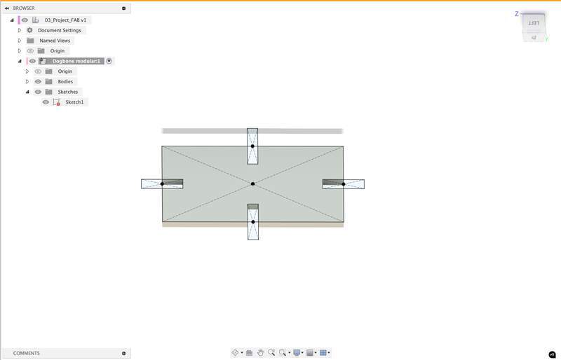
- Extrude sketch profile.
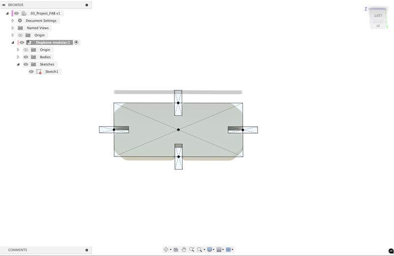
- Add your aesthetic detailing. Arcs were drawn and extruded fillets were added.
- Offset all internal faces of slots by
kerfhalf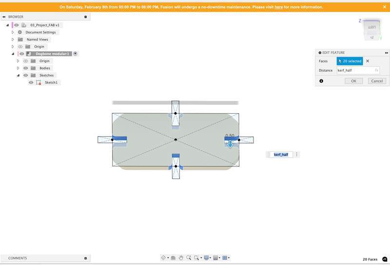
- Export as DXF → go through documented process of laser cutting detailed in the group doc shared on this page.
- Defining parameters
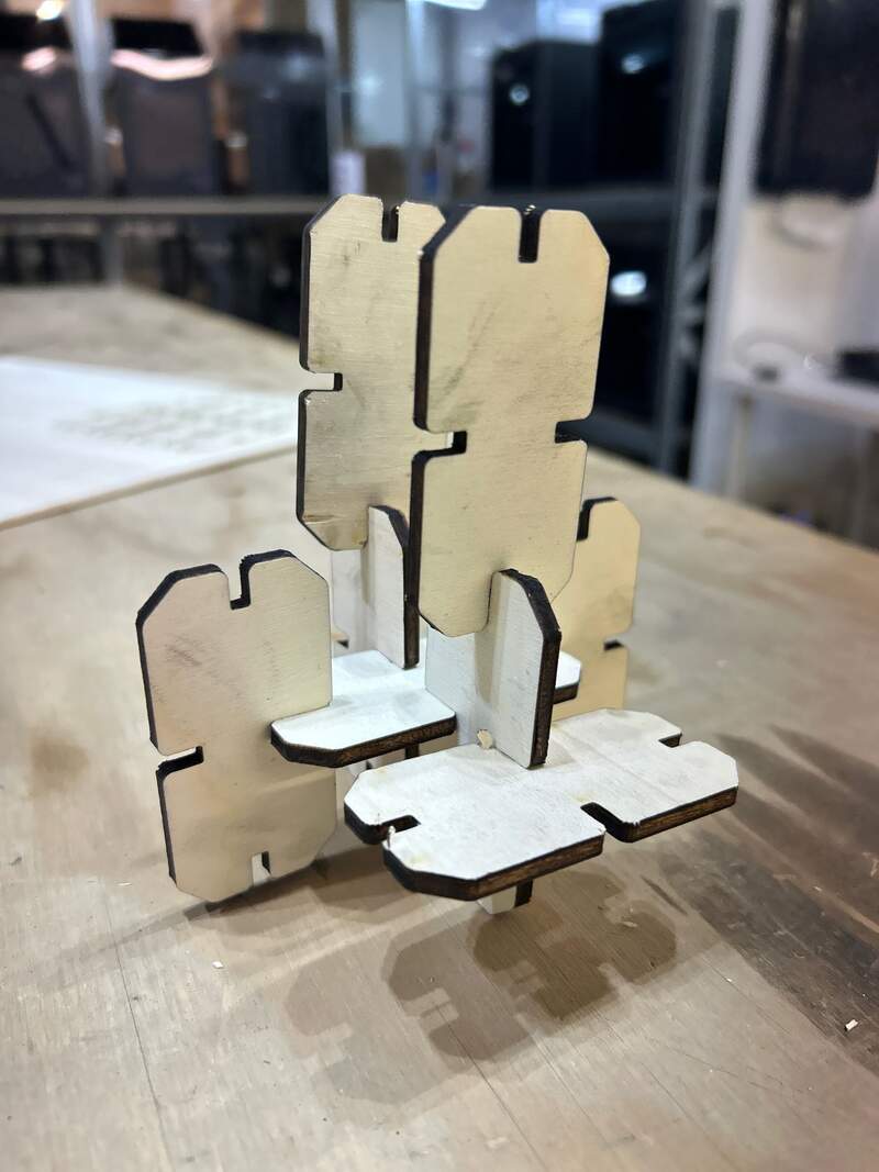
Final Photo
Reflection
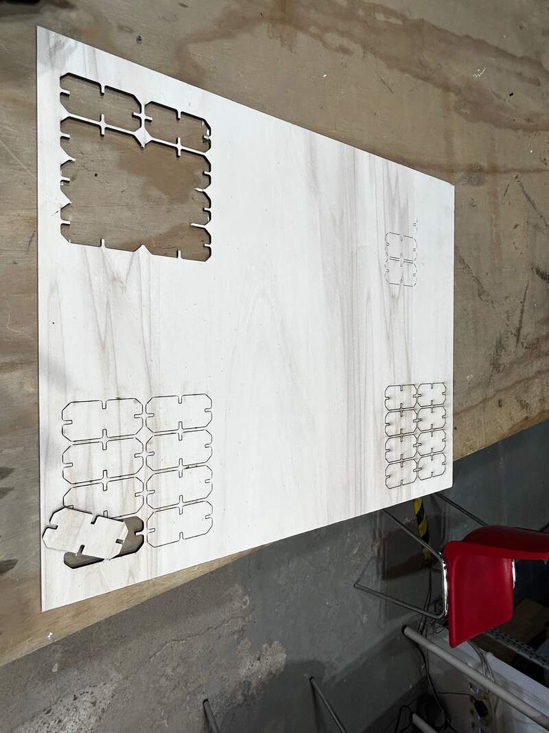
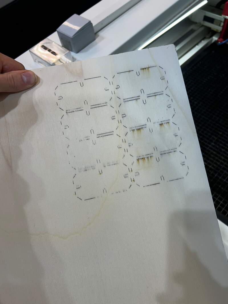
- It took 4 attempts to cut through the material all of the way. With each atempt I noticed that it had cut through on the straightlines, but not the fillets and tight corners. I know the machine effectively speeds up around tight corners. My guess is that the machine was not compensating for this slowdown. I looked through the settings briefly and could not find anything I could tick to correct this. I ended up dialing up both the
powerfrom 45→50 and thespeedfrom 1.6→1.2. This gave me adequate throughcuts.
- I under estimated what would be required of making a truly dynamic module. My module really just want to create cuboid structures. I would need to think harder, but adding diagonal joints would probably allow for modularity between planes.

03—Vinyl Cutter
About the Design
The old place I worked at was technically a sign making company so about half of the bussiness was custom printing on different substrates and laying vinyl. For vinyl and fabrics we primarily used a Zun for things that needed to be cut using a drag knife. The Zun really kicked a lot of ass and was even good as a CNC router table for even routing up to 1/2” plywood. Little jealous… of the Indian Fab Lab that they had these (very expensive) machines. That said for whatever reason I wasn’t that interested in the printing process when I worked there and have regretted because their is quite a lot of nuance to printing and transffering to different materials. I did get a change to lay a lot of vinyl.
That said, I have never used a vinyl plotter before and I had never considered you could use a small plotter like the sillhoutte to cut soft metal and thin plastics in addition to vinyl. For such a low cost tool its pretty powerful.
About My Design
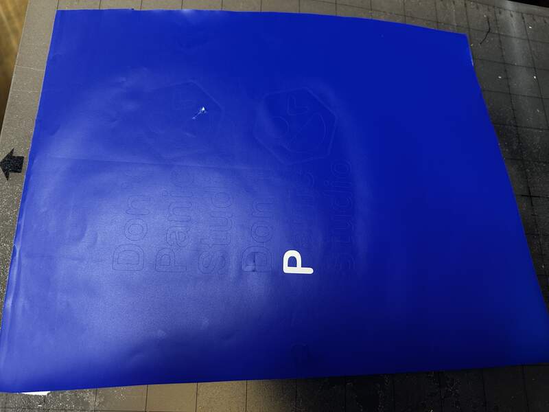
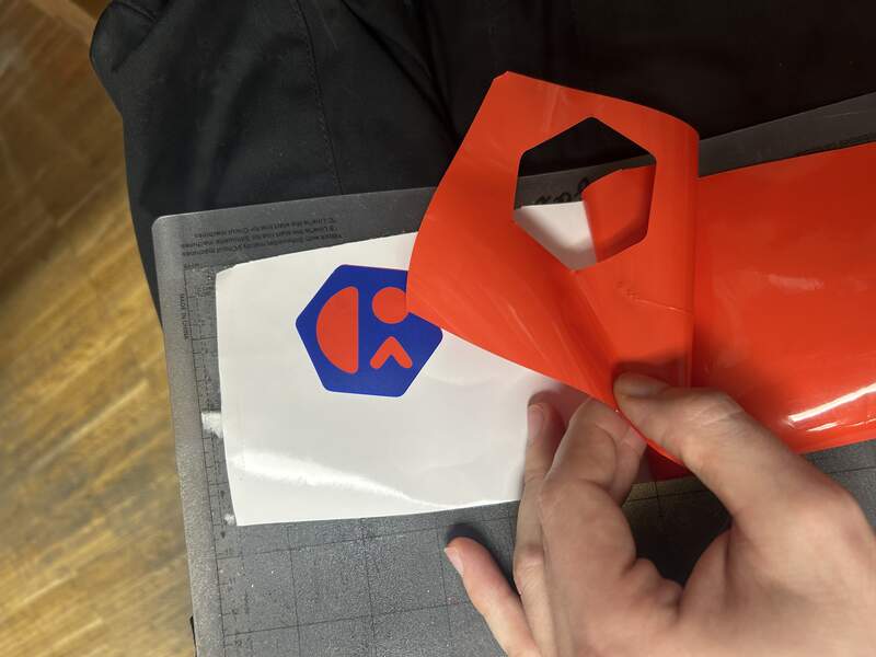
- I chose a logo I had designed for my company, Don’t Panic Studio, based on Hitch Hiker’s Guide to the Galaxy. If your curious the name is a reminder for myself and has nothing to do with the customer’s well-being ;) .
- I had wanted to design something more elaborate, but as with the laser I felt it was best to not overcomplicate the first design as I get comfortable with the machine. Also just wanted this as a sticker for my laptop.
My Design Process
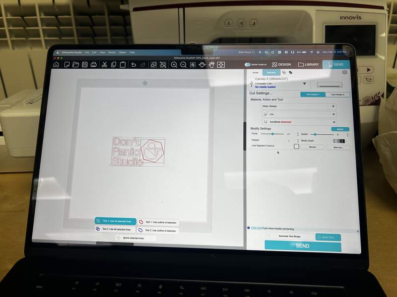
- Import design as SVG into Silhouette
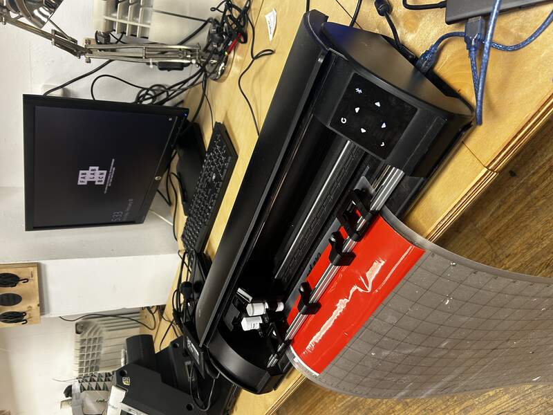
- Setup machine using machine guide recomendations found here.
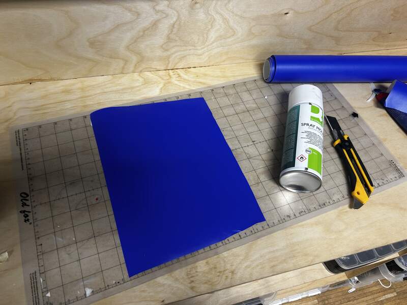
- Use general purpose spray adhesive to temporarily mount precut vinyl.
- Load sheet using load buttons as detailed in manual. Click play button in software.
- Setting are as follows → I just clicked gloss vinyl to match the vinyl substrate I chose and ran it at default setttings.
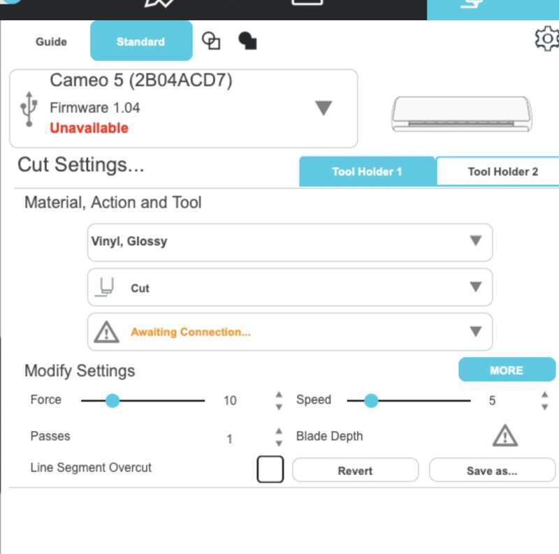
- The first run through didn’t cut through the material fully. I arbitrarily adjusted the force seeting from 10→15 out of its max 40 (whatver this range actually refers to haha). This worked a treat.
- Red was just the design profile wil and offset of about 2mm so it could be covered over with the blue top layer.
Project Files