14—Interface and Application Programming
Assignment
- Group assignment:
- Compare as many tool options as possible.
- Document your work on the group work page and reflect on your individual page what you learned.
- Individual assignment
0—Reflection Why I learn / How I Should Learn
For this week I worked with the Arduino Cloud to create a UI dashboard to trigger the peristaltic pump connected to my Xiao C3 MCU. Aside from the fact that it is browser based software which I find annoying the Arduino cloud is a fantastic platform. Its strength is that it manages all of the webs hosting for you, has an attractive control UI interface (they call the dashboard), and it is compatible with most ESP32 based boards.
As with previous projects I wish I had time to learn more about how to write some of the code myself. It is always a trade off of quality of the work versus quality of learning for me though. I am definitely interested in learning more coding and learning to think like a programmer, but I feel like I lack a lot of the initial context needed to learn at a reasonable pace. For this reason, I hope to maybe take a programming course after fab academy so I can write some of the code myself and more efficiently work with chatbots to generate some of my code.
01— Group Project
In the group project we compared different platform / approaches to develop software interfaces. There are so many options here it is hard to know where to start. Similarly, comparing them is tricky because it really depend what you need to accomplish. In my case I want to control connected projects for configuration or real time performance. So for me what I am most interested is some version of Arduino cloud/streemly or Touch Designer + python so that I could control the setup with a MIDI controller / HID controller.
02— Up and Running with Arduino Cloud
Why the Arduino Cloud Platform
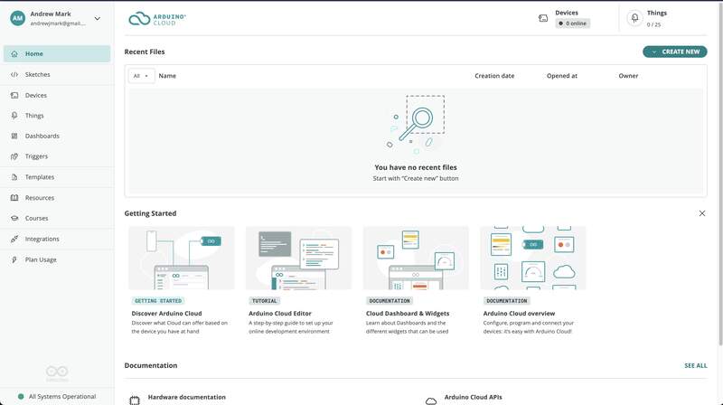
My plan is to make an online web interface as a simple remote for my final project. Since this isn’t a feature I need in my final project so it will serve more as a proof of concept. That said, I think the possibility of having remote control for a project could be useful in the future. In particular I could see it being useful to configure settings remotely on a custom device without the need for a built in interface. As with previous projects I have completed I try to choose tools / platforms that I feel are robust and something I would trust in a permanent work project or art work. I chose Arduino cloud because it has an attractive UI, built in hosting and good documentation. For this reason I was fine paying the $7 a month to test the platform. Soooo let’s go!
Arduino Cloud Setup to Serial Comms
- Before I started I purchased the maker monthly subscription on the Arduino Cloud Website its $7 for the base plan, but I think they have a free trial. Once I logged in I clicked on the discover Arduino cloud options and it led me through a setup wizard where I could select my iPhone as a device that could send information to my Arduino dashboard. To do this I had to first instal the Arduino IoT Remote iPhone app from the app store. I then also had to install a web plugin that operates in my Mac OS taskbar. The website walks you through all of this.
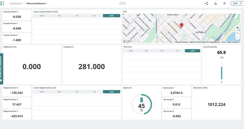
- I then clicked into the dashboard interface that had automatically been created that displays and reads all of the realtime iPhone data. Unfortunately, it was not updating on my iPhone nor the web dashboard. I could not figure out why, but did not spend much time trying to figure it out. I was using my phone as a hot spot and this could have been at least part of the issue. Still not sure why it was not reading the realtime sensor data on my phone or the web interface I decided to move on as this was just a test.
- How to get the Xiao ESP32 C3 Connected to Arduino Cloud when I searched for tutorials I stumbled upon Drone Bot Youtube channel . This guy makes great long form microcontroller tutorials also I discovered he had a blog post for this video that relied on to learn how to use the platform. I actually prefer a good writeup over a video for learning something like this as the information density tends to be higher and allows me to easily return and reread sections I am unclear about. From my reading I learned that there are limitations to which ESP32 boards are supported. In my case the only ESP32 based Xiao that was compatible was the C3. I was originally planning to use the Xiao C6, so I (correctly) anticipated some potential hardware and code issues with switching to a different MCU at this phase in the project.
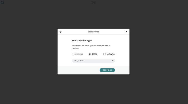
- The actual setup process was quite straightforward. I connected my Xiao C3 over USB and Added it as a device in the Arduino cloud interface. It prompts you to select the type of board you are using. You choose it and then it generates a unique key for you to use when linking.
- Once your device has been successfully created you now need to connect it to the local WIFI network. To do this you first need to create a “thing”. Things are variables that link to the controls on your dashboard used to control your external device. If you do not create a ‘thing’ linked to the device you cannot configure its wifi settings! (this is important and took me some time to figure out). Once you do this you can put in the your local wifi details including the secret key generated in the last step.
- But wait there is more… you now need to flash your board with the code that was auto generated in the Web IDE. This code has all of the wifi data and all of the code that links to the control dashboard. If you want to expand this code you just need to integrate it with whatever your originally developed for the project.
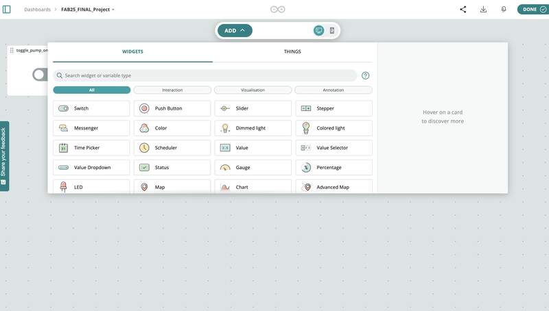
- The dashboard interface needs very little explanation. Except it is important to note the dashboard is not specific to a single project. Your dashboard can include controls for more than one device/project. To edit the dashboard you just click the edit button and add in new elements.
- Using ChatGPT to generate an output that can be read. At this point I just needed to confirm this was going to work. I chose to verify that MCU was receiving the the state change messages over wifi by using a serial print function. I had ChatGPT generate a serial print that would tell me if the button was ON or OFF. Below is the prompt I used.
I am using the following code with arduino cloud all I need you to do is send a serial message when the pump status has been changed. All I need is a serial print function to register that the button is currently toggled on or off
[pasted autogenerated arduino cloud control code here]
- The working code flashed to the Xiao C3
#include "thingProperties.h"

void setup() {
  // Initialize serial and wait for port to open:
  Serial.begin(9600);
  // This delay gives the chance to wait for a Serial Monitor without blocking if none is found
  delay(1500);

  // Defined in thingProperties.h
  initProperties();

  // Connect to Arduino IoT Cloud
  ArduinoCloud.begin(ArduinoIoTPreferredConnection);

  /*
     The following function allows you to obtain more information
     related to the state of network and IoT Cloud connection and errors
     the higher number the more granular information you’ll get.
     The default is 0 (only errors).
     Maximum is 4
 */
  setDebugMessageLevel(2);
  ArduinoCloud.printDebugInfo();
}

void loop() {
  ArduinoCloud.update();
  // Your code here


}


/*
  Since PumpToggle is READ_WRITE variable, onPumpToggleChange() is
  executed every time a new value is received from IoT Cloud.
*/
void onPumpToggleChange()  {
  if (pump_toggle) {
    Serial.println("Pump is ON");
  } else {
    Serial.println("Pump is OFF");
  }
}
- The result
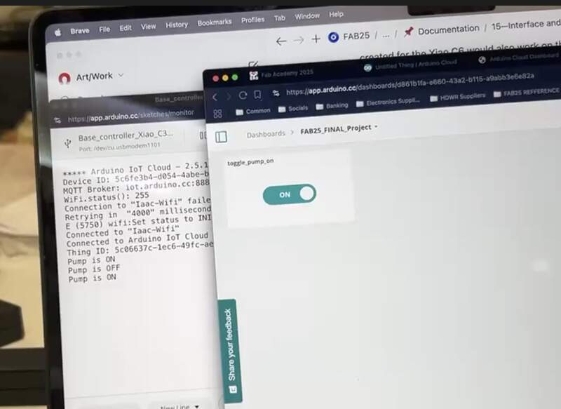
03 — Toggling Pump Using Arduino Cloud
At this point I had confirmed that my dashboard was controlling functions on my controller wirelessly. I also now understood how the Arduino cloud interface worked. The next step was to put it all together and control my Final project circuit over the cloud. From past experience I decided approaching this process in baby steps was the best course of action.
- Validating that the pump control code would work on the Xiao C3. I moved back to the software Arduino IDE uploaded then uploaded and tested the same code that was confirmed to work on the Xiao C6. My hunch was correct and it was confirmed that the same code would not run on the C3.
- To figure out the root cause of this issue I first asked ChatGPT to point out key differences between the board by asking:
The following code works on the Xiao esp32 C6 but not the Xiao esp32 C3 can you look at the specifications of the two boards and the code and tell me why their is this incompatibility issue? Xiao esp32 C6 [pasted pump control code]
- To paraphrase, yes there are core differences in how the C3 handles PWM. This is at least one issue that would cause major problems. Another issue I discovered on my own was that since I was using GPIO pin numbers this numbers mapped to completely different pins on the C3.
- After about 30 min of back and forth I was able to get ChatGPT to generate the code. I did this by first asking:
Can you rewrite the code you have provided previously to work with the xiao C3?I then pasted the console error logs from Arduino multiple times so that it would work through its issues. A persistent error that was made was that the ChatGPT would often refer to old Syntax in the 2.0 version of the ESP32 firmware that had been deprecated. Once I started reading some forums about this I was able to detect when chat GPT was defaulting to the deprecated PWM control code. Similarly, it would try to set the frequency of the PWM signal to 50Hz when the correct frequency was 500Hz because 50Hz was a more common value for servos. \
- Now I had the working code ready and loaded on the the Xiao C3.
- To figure out the root cause of this issue I first asked ChatGPT to point out key differences between the board by asking:
- Merging the Arduino cloud code with the pump control code.
- The code was merged through a simple chatGPT query:
Please integrate the following two code snippets together. The first snippet is for wifi and arduino cloud integration and the second snippet is to control a DFR Robot pump connected to a xiao esp32 C3.
- I faffed about for a while until I realized I moved to a different location and thus a different wifi network. I updated these setting and also remembered to re-atatch the wifi antennae to the Xiao C3. I was now getting confused which C3 I was using and was concerned that the code was relying on a specific device ID. I decided it was smart from now on to give my MCU numbered labels so I could more easily troubleshoot.
- I reverted to the proven original working code and then and then I put in the correct wifi password and it… worked not sure what configuration was the culprit. I then confirmed that the original code was sending serial. Beyond the wifi password I did try different networks so I am not a 100% sure what the root cause of the issue was.
- I repasted the previously integrate pump +wifi control code and… it worked!
- The code was merged through a simple chatGPT query:
- Final result and control code
The final working pump control code
#include <Arduino.h>
#include "thingProperties.h"

// GPIO assignments for the pumps
const int PUMP_PINS[] = {3, 4, 5, 8};           // One pin per pump
const int NUM_PUMPS   = sizeof(PUMP_PINS) / sizeof(PUMP_PINS[0]);

// PWM configuration
const int PWM_FREQ        = 500;               // 500 Hz as per pump specs
const int PWM_RES_BITS    = 8;                 // 8-bit resolution
const int PERIOD_US       = 1000000 / PWM_FREQ;

// Pulse widths in microseconds
const int PULSE_ON_US     = 950;               // Medium forward speed
const int PULSE_STOP_US   = 1500;              // Stop (center position)

// LEDC channel assignments
const int LEDC_CHANNELS[] = {0, 1, 2, 3};       // Assign a unique channel to each pump

// Duty cycles
uint32_t dutyOn;
uint32_t dutyOff;

void setup() {
  // Initialize serial and wait for port to open:
  Serial.begin(115200);
  delay(1500);

  // Initialize IoT Cloud properties
  initProperties();

  // Connect to Arduino IoT Cloud
  ArduinoCloud.begin(ArduinoIoTPreferredConnection);

  // Set debug message level
  setDebugMessageLevel(2);
  ArduinoCloud.printDebugInfo();

  Serial.println("Initializing 4 peristaltic pumps (GPIO 3, 4, 5, 8) with 500 Hz PWM signal...");

  // Calculate duty cycles
  uint32_t maxCount = (1 << PWM_RES_BITS) - 1;
  dutyOn  = (PULSE_ON_US * maxCount) / PERIOD_US;
  dutyOff = (PULSE_STOP_US * maxCount) / PERIOD_US;

  // Attach PWM to each pump pin using the LEDC API
  for (int i = 0; i < NUM_PUMPS; i++) {
    ledcSetup(LEDC_CHANNELS[i], PWM_FREQ, PWM_RES_BITS);
    ledcAttachPin(PUMP_PINS[i], LEDC_CHANNELS[i]);
    // Initialize pumps to OFF state
    ledcWrite(LEDC_CHANNELS[i], dutyOff);
  }

  Serial.println("Pumps initialized and stopped.");
}

void loop() {
  ArduinoCloud.update();
  // Additional code can be added here if needed
}

/*
  Since pump_toggle is a READ_WRITE variable, onPumpToggleChange() is
  executed every time a new value is received from IoT Cloud.
*/
void onPumpToggleChange()  {
  if (pump_toggle) {
    Serial.println("Pump is ON");
    pump_read_status = "ON";
    for (int i = 0; i < NUM_PUMPS; i++) {
      ledcWrite(LEDC_CHANNELS[i], dutyOn);
    }
  } else {
    Serial.println("Pump is OFF");
    pump_read_status = "OFF";
    for (int i = 0; i < NUM_PUMPS; i++) {
      ledcWrite(LEDC_CHANNELS[i], dutyOff);
    }
  }
}
Proof ;)
04— Next steps
Even though the result of this work is pretty basic I feel I could easily extend the control pretty far. I see myself wanting to use an interface like this to configure a project remotely. Doing this would probably require the board to have some built in storage to save the settings if the device is rebooted. I think the ability to have control like this at your fingertips is really great, but I don’t think I ever want to build an interactive project that relies on wifi to work.
Files
- Final working code is included in the text body.
References
- All references are included in the text body