10—Output Devices
Assignment
- Group assignment:
- Measure the power consumption of an output device.
- Document your work on the group work page and reflect on your individual page what you learned.
- Individual assignment:
- Add an output device to a microcontroller board you’ve designed and program it to do something.
00—Reflection
Mentally I felt split across a lot of different things this week. Mainly I had to get my evaluation milled board finished which was keeping me from completing last weeks assignment. Getting it finished was this sensation of feeling behind and then when I got it working it felt like a very big win. In particular getting the I2C working was a big relief. As I have said in the past I am not so interested in really creating PCBs from the ground up for the most part I am going to use prebuilt sensor modules.
With this milled PCB I am finally seeing my own workflow develop for creating reliable PCBs for myself. This is satisfying because getting a PCB design functioning in the real world has proved to be such a struggle.
01— Group Project
For the group project I personally tested a motor using a MOSFET on a motor circuit. I had never set this up or really used MOSFETs in the past so wanted to have better understanding of what this entailed. I initially made a wiring mistake and then I made a mistake in how I was signalling the MOSFET. The signaling issue was resolved when I compared how I was handling the PWM compared to examples I found online.
Click here to see this weeks group project.
02— Topics from class
- Ohms law online resource https://phet.colorado.edu/sims/html/ohms-law/latest/ohms-law_en.html
- Neo pixels and PWM
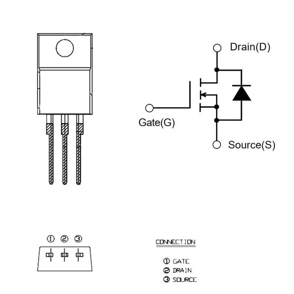
- N channel vs P channel MOSFETs
- N-Channel switch to ground
- P-Channel switch to supply
- The modern approach for small screens is OLED
- I2S is a very robust audio I/O approach
- BLDCs need an ESC for control
- Stepper motors
- Stepper driver have two h bridges embedded + other circuits for logic
- micron wire is high resistive wire that heats when energy is applied
MOSFETs
| N-Channel | P-Channel | |
|---|---|---|
| Enhancement type | Low Side Switch | Hi Side Switch |
| Enhancement type | Normally off | Normally Off |
| Depletion Type | Normally on | Normally on |
- Your drain is your ground
- Your source is your intended source ie. a motor
- Your gate is from the microcontroller
- Can be controlled by PWM or just using high and low commands
- Source is your input voltage
- Drain is your load
DC Motors (brushed)
- Stall current will increase current draw significantly
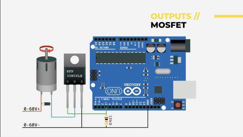
- A motor will need a MOSFET to be controlled through something like an Arduino (below would be a typical configuration).
- EMF — must be managed with a motor
- Flyback Diode
Keeps voltage from being sent backwards into the circuit from the magnetic field that is created by the motor.
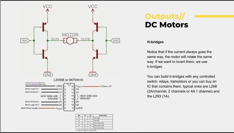
- If you want to control forward and backwards motion you will need an H bridge
Servos
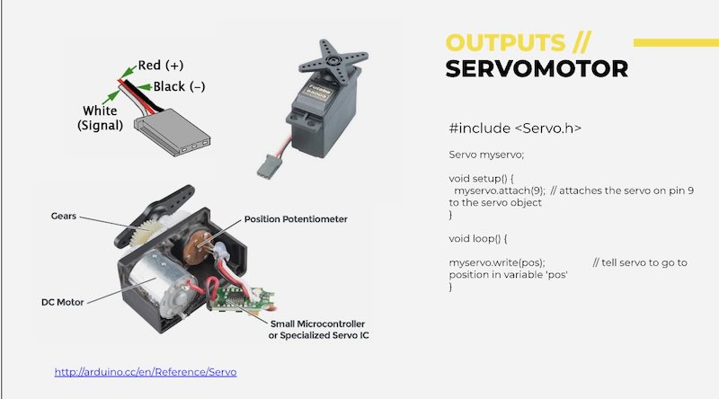
Below is a diagram of a basic servo motor. The potentiometer always provides a resistance value as it has a definite beginning and end point. It essentially samples this value to know it position.
Nitonal
- You heat it up past a certain temperature (quickly and constrained by a jig) then quench it.
- Every time you heat it up it will return to its state
- Thick gauge nitonal is pretty strong
LEDs
MCU controlled / addressable LEDs
- Neopixels
- Technically are supposed to be controlled with 5v logic but can be controlled with 3.3V
- Lines with a clock in addition to data line (6pins in the case of RGB) have better control and timing
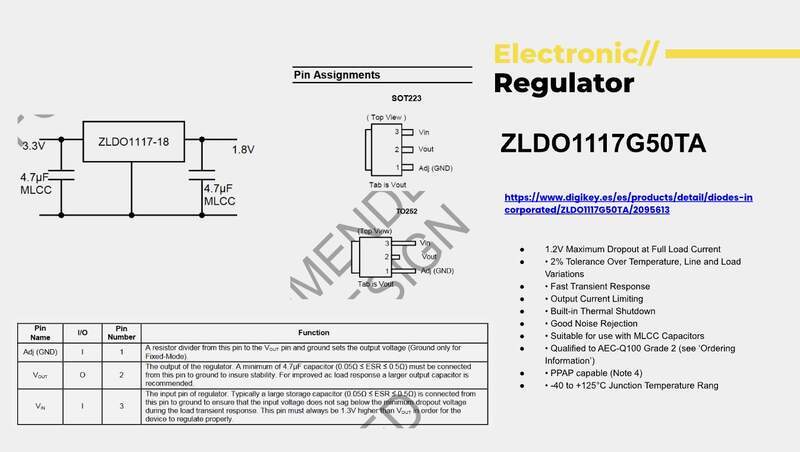
Regulators
Below is a common regulator that is used.
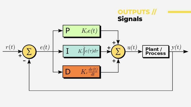
PID and Other Control Regimes
Is a control methodology implemented in code. Naturally in an output context is also requires a responsive output system.
Open vs Closed Loop
- Open has no receiving end to sample the action instigated.
- Closed means it is sampling the result of it action and comparing it too its intended value.
- Proportional control will overshoot you need to mix it with other tracking architectures
- Its essentially acceleration modulation
03— Grove OLED Screen (I2C)
I needed to quickly find an output device that ran on I2C so I chose a grove OLED screen. To get to this point of testing I had to do a lot of trouble shooting on my evaluation board. This troubleshooting was added to the input devices week. So after I got stable power an operation from the Xiao I wanted to test the I2C lines next.
- To start I selected the grove SSD1315 OLED display. I confirmed it was an I2C grove device by looking at the silkscreen on the board and then searched for it on the Seeed wiki to check if it had any dependancies.
- After reading the dependancies I noted that it utilized the
U8g2lib.hlibrary one that I had previously installed.
- To get it running I simply copied and uploaded their demo code to check functionality.
#include <Arduino.h>
#include <U8g2lib.h>

#ifdef U8X8_HAVE_HW_SPI
#include <SPI.h>
#endif
#ifdef U8X8_HAVE_HW_I2C
#include <Wire.h>
#endif


U8G2_SSD1306_128X64_NONAME_F_HW_I2C u8g2(U8G2_R0, /* clock=*/ SCL, /* data=*/ SDA, /* reset=*/ U8X8_PIN_NONE);  // High speed I2C

// U8G2_SSD1306_128X64_NONAME_F_SW_I2C u8g2(U8G2_R0, /* clock=*/ SCL, /* data=*/ SDA, /* reset=*/ U8X8_PIN_NONE);    //Low spped I2C

void setup(void) {
  u8g2.begin();
}

void loop(void) {
  u8g2.clearBuffer();                   // clear the internal memory
  u8g2.setFont(u8g2_font_ncenB08_tr);   // choose a suitable font
  u8g2.drawStr(0,10,"Hello World!");    // write something to the internal memory
  u8g2.sendBuffer();                    // transfer internal memory to the display
  delay(1000);
}
- Ran it on my custom eval board (documentation can be found in inputs week) and it worked first try! Then I confirmed that the other I2C line worked and it did!
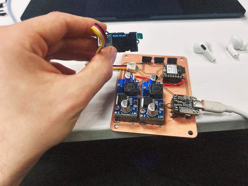
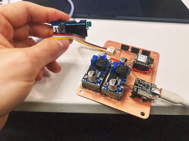
- After this I just modified the display text to do just a bit of personalization of the output. Interestingly the text is getting cut off. I assumed it would have some logic to overflow iot onto the next line, but I guess this needs to be called out explicitly in the code.
03— DFR Peristaltic Pump
The DFR Peristaltic pump has additional circuitry on board to be handled like a servo motor through a single digital control wire. This was why I chose to spend extra money for this specific version.
- First I made sure to connect the motor correctly to my output pin sockets that were created for pump control.
- Then I loaded this code in for control. This code I had originally made in cursor through several hours of back in forth to get right. Given this struggle I plan to go back to this to get a better sense of exactly how this works. I will need to do this anyway to get the kind of percise control I need to do this. For now though here is code that I confirmed works using Seeed’s commercial Xiao interface board that I am now testing on my personal Evaluation board.
#include <Arduino.h>
#include <ESP32Servo.h>

// Pin configuration for Xiao ESP32-C3
const int PUMP_PIN = 9;  // Using GPIO 9 for servo control
const int LED_PIN = 21;   // Built-in LED pin for Xiao ESP32-C3

// Pump control settings
const int ON_TIME = 2000;    // Run time in milliseconds (2 seconds)
const int OFF_TIME = 1000;   // Pause time in milliseconds (1 second)

// Servo angles for pump control
const int ANGLE_FORWARD = 180;  // Full speed forward
const int ANGLE_STOP = 90;      // Stop position
const int ANGLE_REVERSE = 0;    // Full speed reverse

Servo pumpServo;  // Create servo object

void setup() {
  // Initialize serial communication for debugging
  Serial.begin(115200);
  delay(3000);  // Give serial time to initialize

  // Flash onboard LED to indicate program is running
  pinMode(LED_PIN, OUTPUT);
  digitalWrite(LED_PIN, HIGH);
  delay(100);
  digitalWrite(LED_PIN, LOW);

  Serial.println("Starting pump initialization...");

  // Configure ESP32 PWM channels
  ESP32PWM::allocateTimer(0);
  ESP32PWM::allocateTimer(1);
  ESP32PWM::allocateTimer(2);
  ESP32PWM::allocateTimer(3);

  // Attach servo to pin with proper pulse width range
  pumpServo.setPeriodHertz(50);  // Standard 50Hz servo
  pumpServo.attach(PUMP_PIN, 500, 2500);  // 500-2500μs pulse width range

  // Initialize pump to stop position
  pumpServo.write(ANGLE_STOP);
  delay(1000);  // Give servo time to move to initial position

  Serial.println("DFR Peristaltic Pump Test Started");
  Serial.println("WARNING: This pump requires external 5V-6V power supply!");
  Serial.println("Maximum current draw: 1.8A continuous, 2.5A peak");
  Serial.print("Using Pin: ");
  Serial.println(PUMP_PIN);
}

void loop() {
  // Turn pump ON (Forward)
  Serial.println("Pump ON - Forward");
  pumpServo.write(ANGLE_FORWARD);
  delay(ON_TIME);

  // Turn pump OFF (Stop)
  Serial.println("Pump OFF - Stop");
  pumpServo.write(ANGLE_STOP);
  delay(OFF_TIME);
}
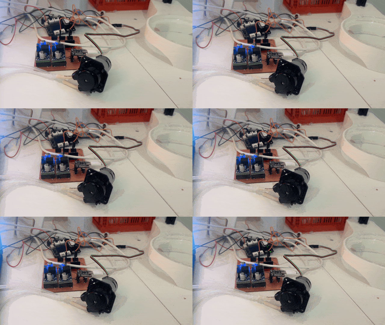
- The when I set everything up on my test board the motor was not working. Since I had already successfully ran the code with the Xiao carrier board and my custom power supply I knew this was neither a problem with my power nor my code. I realized I had arbitrarily chosen pin 0,1 and 2 as my pump control servo output on my evaluation board. In hindsight this was an oversight I had wrongly assumed that any of the pins could provide the PWM that the motor needed for control this is not the case on the Xiao C3. So I jerry rigged the original Xiao carrier board to get the whole thing functioning by using pin 9.
- Recorded power consumption is… and shit. I put my DMM in the wrong place and shorted the control circuit in my motor. Good thing I have another one. This is why I always use a variable power supply and or a clamp meter energy consumption. Live and learn… again I guess. I think I will just purchase an inline USB C DMM. Nominal consumption of my motor is 5W I would imagine I am under utilizing it significantly so my guess would be <5W let say 2.5W. I will meter this later… or I think I can implement realtime current consumption monitoring from my USB C power input.
- Below is proof that it actually works. You can view it it working context on my Final project page. For my next version I will be more careful to consider the pin capabilities of the Xiao C3 to avoid this issue. As mentioned in the reflection section I will be writing up a full plan to redesign my evaluation board with a list of many of the changes that need to be implemented to address the issues I found in how it powers the Xiao and how it handles GPIO. Some of these changes will include
- 5v input to Xiao with appropriate Shottkey protection diode
- Dual row sockets for Xiao C3
- New pin selections for PWM control
- Updated busses for grove connector (3x digital 1x analog and 1x I2c)
- On / Off switch
Project Files
All Code is provided in the body text.
