Final Project: Electronics & Control
01—Hardware
Further Research: Electrical
Diode for back current
- What specific cable to use for UART comms
Answer: cat 5 / cat 6 / ethernet cable should be fine
- Can I2C and UART be sent out at the same time from the XIAO?
Answer: I am now just using I2C as my communication line
- What specific Diode to use to handle back voltage
Answer: The current shottkey I have chosen should be sufficient
- What Specific Resistor should be used for I2C line
- Some I2C line do not need resistors double check that this is the case for you
- Watched this video about I2C resistors
- lower value resistor faster speeds lower power
- what does Open drain mean?
V1 PCB testing Regime
v1 PCB Fixes
- Properly desolder 5V on both buck converters
- Design 3D printed standoff for HUSB
- 5v breakout on Send
v2 Running Change List
- Sort out how UART could be changed to I2C
- lower profile screw terminals
- Add Xiao pin number to all GPIO / communication silk names
- GPIO ports have the GND side swapped
- I2C_3 need to be connected
- Remap GPIO to not use pin 1
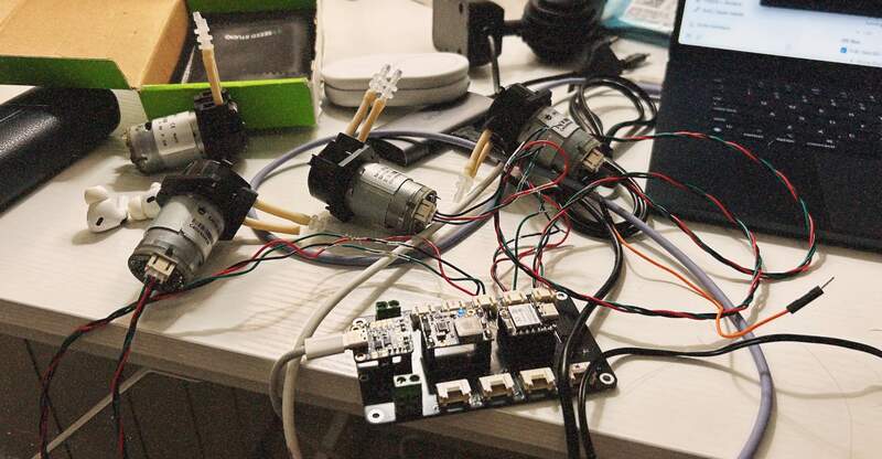
V1 PCB Physical Testing
Basic Testing
PCB PWR
- T: GND is GND
- B: GND is GND
- T: 3V3 lines are 3V3
- B: 3V3 lines are 3V3
- T: 5V lines are 5V
- B: 5V lines are 5V
HUSB in
- T: confirm +5V Out off board
- B: confirm +5V Out off board
Buck Converter
- T: 3V3 output from buck
- B: 3V3 output from buck
Xiao ESP32 C3
- T: Xiao Powers on
- ⁉️PWR light seems to be blinking rapidly, confirmed that 1 of these Xiaos (labelled Xiao 2) exhibits this behavior while the other does not
- B: Xiao Powers on
- T: Confirm all Xiao Pin mapping
- B: Confirm all Xiao Pin mapping
PWR Switch
- T: PWR switch functioning
- B: PWR switch functioning
External Spotlight
- Disassemble and measure V+ input of external spotlight
Shottkey Diodes (optional)
- B: board PWR IN and XIAO toggle PWR in
- T: board PWR IN and XIAO toggle PWR in
Advanced Testing
PUMP GPIO
- T: Test 1-4 GPIO for pump functioning
- Pump not working
- tested alternate pump
- tested alternate Xiao
- fixed ground / signal mix up in wiring for PCB female connectors
- ChatGPT when asked to simplify the code and generate PPM from basic PWM was defualting to old syntax for the esspresif boards for the LEDC functions
- I switched over to the Xiao ESP32 c6 as I had suspicions that the arbitrary switch to the c3 could have been causing the new issues
- New pumps seem to have initial resistance and take several minutes of running to “loosen up”
- GPIO pins are being called out (not digital IE d8) so when you change the pin it coresponds to the GPIO assignment not its digital or analog number
- GPIO 19, 2, 21 are confirmed to work to send pump control PPM, and all 3 can run separately but running all 3 requires different implementation
- T: All pumps working simultaneously on GPIO 19, 2, 21
I2C Bus
- T+B: Test I2C with grove display
- Grove display works with both T+B I2C_1 and I2C_2 Power must be cycled for it to be operational. I2C_3 is confirmed to be disconnected from SDA and SCL
- B: Test all I2C grove ports with all MM_wave (1-3)
- B: Run DFR encoder (SEN0502) with test code on I2C bus
UART COMMS
- B: confirm serial send and receive communication
- T: confirm serial send and receive communication
- T+B: Test board to board UART comms
- T+B: Test board to board UART with long cable
- Test continuity on long cable
Electronics BOM [ ]
BOM: v1_Design (SENDER + RECEIVER)
%201c8d790de3e580b39914e14d9f92da9b/Adafruit%20USB%20Type%20C%20Power%20Delivery%20Dummy%20Breakout%20%201c8d790de3e5809e8887e51c79e1898c/CleanShot_2025-04-01_at_15.57.162x.jpg)
%201c8d790de3e580b39914e14d9f92da9b/DC-DC%20Multi-output%20Buck%20Converter%20(3%203V%205V%209V%2012V)%201c8d790de3e580a3afacd041c1ea85c7/CleanShot_2025-04-01_at_21.41.062x.jpg)
%201c8d790de3e580b39914e14d9f92da9b/Gravity%20Digital%20Peristaltic%20Pump%201c8d790de3e5802bb8b7fd059dd0e6c9/CleanShot_2025-04-01_at_15.44.332x.jpg)
%201c8d790de3e580b39914e14d9f92da9b/Gravity%20360%20Degree%20Rotary%20Encoder%20Module%201c8d790de3e580269b98ffd6d57f3119/CleanShot_2025-04-01_at_15.44.262x.jpg)
%201c8d790de3e580b39914e14d9f92da9b/Grove%20-%20OLED%20Display%200%2096%20(SSD1315)%20I2C%20Interface%20%201c8d790de3e58059b764c045e4f489d7/CleanShot_2025-04-01_at_15.44.002x.jpg)
%201c8d790de3e580b39914e14d9f92da9b/Gravity%20MAX30102%20PPG%20Heart%20Rate%20and%20Oximeter%20Senso%201c9d790de3e58064bd7fe0415a618ba0/CleanShot_2025-04-02_at_16.15.302x.jpg)
%201c8d790de3e580b39914e14d9f92da9b/XIAO%2060GHz%20mmWave%20Human%20Breathing%20and%20Heartbeat%20Se%201c8d790de3e5801492a8f47e398d0352/CleanShot_2025-04-01_at_15.44.192x.jpg)
%201c8d790de3e580b39914e14d9f92da9b/4%207%20kOhms%20%C2%B11%25%200%2025W,%201%204W%20Resistencia%20en%20microproc%201c8d790de3e580a8a337d8fb7ac00779/R0566046-06.webp)
%201c8d790de3e580b39914e14d9f92da9b/DIODE%20SCHOTTKY%2040V%201A%20DO214AC%20%5BSS14%5D%201c8d790de3e580f383b2e5dd55f5caa8/CleanShot_2025-04-01_at_15.52.512x.jpg)
%201c8d790de3e580b39914e14d9f92da9b/Rocker%20Switch%20SPST%2010A%20(AC)%20125%20V%20Panel%20Mount,%20Sna%201c8d790de3e580f98bf5e3c8724723bc/CleanShot_2025-04-01_at_15.44.092x.jpg)
%201c8d790de3e580b39914e14d9f92da9b/7%20Posiciones%20Cabecera%20Conector%200%20100%20(2%2054mm)%20Orif%201c8d790de3e580298273d1871d9947c8/CleanShot_2025-04-02_at_17.42.472x.jpg)
%201c8d790de3e580b39914e14d9f92da9b/BUSOHE%20Cat%208%20Ethernet%20Cable%2010M,%20Flat%20Network%20Cabl%201c8d790de3e58075b37dc82a7c945d6b/CleanShot_2025-04-01_at_22.54.092x.jpg)
%201c8d790de3e580b39914e14d9f92da9b/2%20Position%20Wire%20to%20Board%20Terminal%20Block%20Horizontal%201c8d790de3e580309baed55590818aa2/CleanShot_2025-04-01_at_15.45.082x.jpg)
%201c8d790de3e580b39914e14d9f92da9b/GROVE%20CABLE%204POS%2050CM%202PACK%20%5BA034-C%5D%201c8d790de3e5800c9c61ea3530cf0944/CleanShot_2025-04-01_at_22.01.582x.jpg)
%201c8d790de3e580b39914e14d9f92da9b/Gravity%20Digital%20Sensor%20Cable%20for%20Arduino%20-%2050cm%20(1%201cdd790de3e580919f3eccc59aba4d9d/CleanShot_2025-04-06_at_22.08.022x.jpg)
%201c8d790de3e580b39914e14d9f92da9b/CONN%20HEADER%20VERT%203POS%202%2054MM%201c8d790de3e580bdb3b1c2d18b5fe7b0/CleanShot_2025-04-01_at_16.09.342x.jpg)
%201c8d790de3e580b39914e14d9f92da9b/CONN%20HEADER%20R%20A%203POS%202MM%20%5BS3B-PH-SM4-TB%5D%201c8d790de3e580199b56df89ae2f7377/CleanShot_2025-04-06_at_21.54.542x.jpg)
%201c8d790de3e580b39914e14d9f92da9b/GROVE%20FEMALE%20HEADER%20R%20A%2020PACK%201cdd790de3e58001a241f454fbc45b3e/CleanShot_2025-04-06_at_22.02.342x.jpg)
Initial Component Research
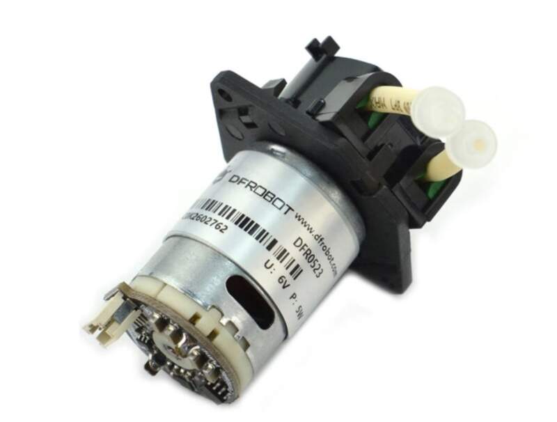
Peristaltic Pumps
DFRobot — PPM Peristaltic Pump
- I am currently evaluating the DFR peristaltic pump. It seems to be quite responsive I would prefer if it were a bit quieter though.
- PPM control is important whatever pump I use it needs to be easy to actuate precisely.
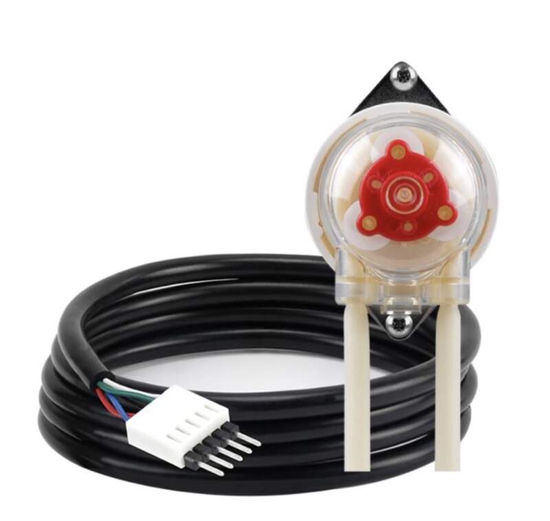
Atlas Scientific — EZ Pump
- Looks very promising and has an I2C interface which making IO management on the Xiao much easier. 4 times the cost as the DFR pump.
- Noise seems to be the same as DFR
- Easier communication and calibration compared to the DFR Peristaltic
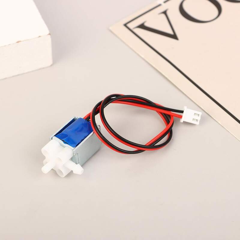
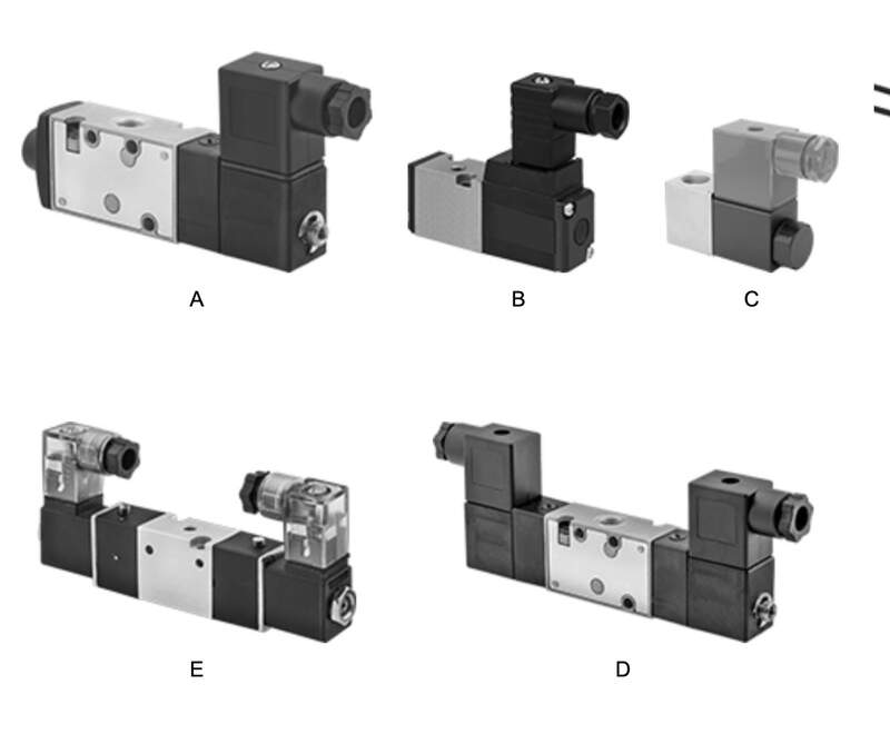
Solenoid Valves
Air solenoid valves
- I think the air valves are more appropriate because the seem to come in smaller sizes. I am not sure quality is so relevant here. Similarly, I am not sure if it should matter that it is made for preasurized air and not water as the use case is pretty light.
- Sound and dosing accuracy are a big concern and I am not sure if solenoids are an improvement over the peristaltic pump approach.
High Performance Cartridge Style Valves
- There is a lot of product differentiation in this space and I don’t know the first thing about these. This cartridge style seems to be common in industrial automation. I have also seen them used on high end large format printers.
Component Specification Reference
Xiao C6
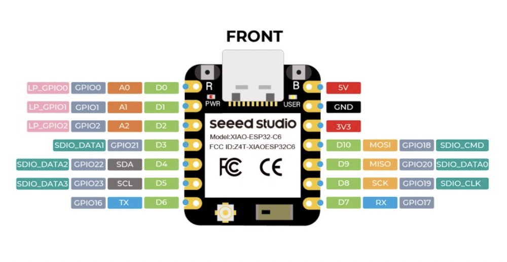
At a glance:
- Bootloader mode
- Step 1. Press and hold the BOOT button on the XIAO ESP32C6 without releasing it.
- Step 2. Keep the BOOT button pressed and then connect to the computer via the data cable. Release the BOOT button after connecting to the computer.
- Step 3. Upload the Blink program to check the operation of the XIAO ESP32C6.
Xiao C3
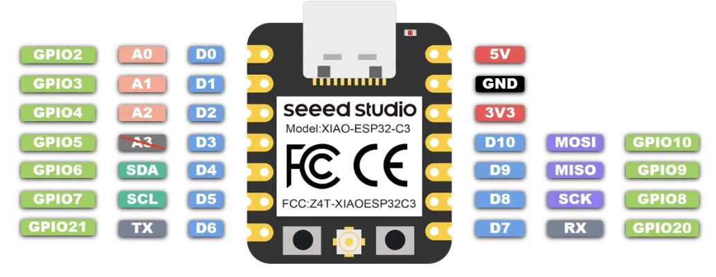
At a glance
- Connection type Grove I2C 3.3 or 5V
- vcc = 3.3V or 5V
- Max W = .5 (for 4) = 2 W
Key Specs
- Human Static Presence Detection: up to 6 Meters
- Breathing and Heartbeat Detection: 1.5 Meters
- WS2812 RGB LED (neopixel) onboard
- Sensor will get best reading pointed at chest
DFR Peristaltic Pump
Seeed MR60BHA2 MM Wave [60 Ghz]
DFR I2C Heart Rate Sensor
DC-DC Multi-output Buck Converter (3.3V/5V/9V/12V)[DFR1015]
Process Documentation
KiCAD library to Flux Library
I am writing this for posterity. The process of importing components in flux is very complicated and convoluted. There are more details, but here are the broad strokes. So I don’t forget how to do this.
- Upload your KiCAD sym into the main hub (before you make a project)
- This will automatically import details and symbol.
- Add your footprint and step in the asset manager panel.
- You now need to link them in the footprint panel mode. You do this by selecting the footprint object in the objects panel adding an asset rule and selecting the footprint .mods file for the component.
- The same approach is taken for the 3D step model, but by creating a new 3D model object in the ‘objects panel’ adding asset selector and then your 3D model.
- Last step is publishing the part.
- Part needs to be reopened in a fresh document to view the custom symbol.
How to smooth sensor data
- Moving average / exponential smoothing
- Average the heart rate input over a period of time.
- Events based measurement (not time)
- Focus on smoothing the data versus accuracy
03— Software DEV
Roadmap
Goal: A limited version of the full program with a single DFR pulse sensor to reduce complexity of the system. It should be able to pass processed sensor data from the Sender to the receiver to actuate a pump at the specified rate.
- Receiver: Pump multi_pulse_control over serial
- Sender: I2C bus to read single and print to console dfr_heart_sensor
- Sender/Receiver: send_and_receive code
- Sender/Receiver: (dfr_heart_sensor_send) + (pulse_control_receive)
Program descriptions
Phase 1
- multi_pulse_control
Overview: This program is written for the Xiao C3 connected to 3 DFR peristaltic pumps the program’s purpose is to control the rate and duration the pumps actuate for from a serial input.
- Per Pump Pulse Control—control each pump independently. The control I need for each pump is the ability to take a number [max input = 180] that will dictate the number of pules the pump makes per minute (
pulse_pm).
- Global Single Pulse duration—All pump will have a global pulse duration that is set early in the program. This global pulse duration allows me to calibrate the pump actuation.
- Serial control for debugging— all 3 pump objects should be controllable through the serial console using serial commands written in the Arduino IDE. You should be able to call out a pump by its identifier and the number of pulses you want it to actuate with [0] being off. The status of each pump should be listed on a single line in the serial console and updated every second.
- Per Pump Pulse Control—control each pump independently. The control I need for each pump is the ability to take a number [max input = 180] that will dictate the number of pules the pump makes per minute (
- dfr_heart_sensor
Overview: This program is written for the the Xiao C3 connected to DFR MAX30102 pulse oximetry sensor over I2C. The purpose of it is to read and print values from this sensor to the serial console in Arduino IDE.
- The program should be able to read the sensor from its I2C bus and interpret the values for the heart rate variable using a rolling average method to reduce jitter in the data. The resulting values should be printed every 2 seconds to the serial console in Arduino IDE for debugging.
- The name of the sensor should be
heartsense_1as later the code will need to be expanded to accommodate 3 sensors (ieheartsense_2,heartsense_3)
- Heart rate value divider— I will need the option to globally apply a division operator to all heart rate BPM values the result of this will be called
pulse_pm.
- test_receive and test_send
Overview: This program is intended to pass a value with an identifier from a board named ‘sender’ (Xiao ESP32 C3) to another board named ‘receiver’ (Xiao ESP32 C3). The goal is to confirm that the messages has been received and that the integrity of the message is intact. To do this the program should send the message over the default UART pins between the two MCUs [GPIO 21 TX GPIO 20 RX]. The baud rate for sending between the controllers can be very slow as a delay of 25ms from sender to receiver would be acceptable. More specific details are below.
- The value sent should be an identifier + value it should look like:
heartsense_1 pulse_pm ###heartsense_2 pulse_pm ###heartsense_3 pulse_pm ###. The number in each previously mentioned item is just a place holder value that can be randomly selected.
- I need to be able to confirm that the message has been received through the serial console
- Please be very careful to consider the specific MCUs I am using as well as the fact that I am using the latest versions of the Arduino IDE and Esspresif board packages and any included libraries.
- The value sent should be an identifier + value it should look like:
- (pulse_control_receive)
Overview: This program will read values sent from test_send and actuate the pump object based on the pulse_pm value it receives.
- (dfr_heart_sensor_send)
- (multi_dfr_heart_sensor_send) + (multi_pulse_control_receive)
Phase 2
Goal: Get all 3 SEED mm wave sensors working.
- Sender: mm_wave_heart_sensor
- Sender: multi_mm_wave_heart_sensor
- Heart rate input sampling + Arduino Cloud
- Heart and Breath rate per minute are read from 1 R60BHA2 mm wave sensor and can be displayed in the serial console for debugging. Code is written to easily distinguish sensors from each other when all 3 are added later.
- MR60BHA2 Program
- I have a hardware setup where I am reading data from 3 MR60BHA2 mm wave sensors. Each of these MR60BHA2 sensors include a Xiao ESP32 C6. These 3 Xiao ESP32 C6’s are then connected to an I2C bus through the pins D10 [SDA] and D0 [SCL]. A library called Seeed_Arduino_mmWave.h exists to read data from these sensors and should be used.
- The generated code should read sensor data from the Xiao ESP32 C6 and send the information to be read by the Xiao ESP32 C3 to be read from the I2C bus every 2 seconds.
- Human detection feature written in console as “Human [yes] or [no]”
- Beats per minute written as “BPM [#]”
- Breath rate written as “BR [#]
- Since 3 sensors will share the bus it is important that the code includes the names Heartsense_1, Heartsense_2, or Heartsense_3 as an identifier. Similarly, each sensor will need its own unique I2C address. Please choose an I2C address in code comments provide 3 additional I2C addresses that could be used.
- The code should also include the ability to connect the board to a computer directly (not using the I2C) bus so that the information above could be read in the serial console for debugging.
- SENDER Code
- Earlier I generated code that is loaded onto a Xiao ESP32 C6 that reads information from the MR60BHA2 mm wave sensors. What I need to do now is create code for a Xiao ESP32 C3 that reads these sensors from its connected I2C bus. Object names for the 3 sensors inputs are Heartsense_1, Heartsense_2, and Hearsense_3. The code should parse the following items for all 3 sensors on a single line as the data comes in and should be viewable in the serial console for debugging
- Human detection feature written in console as “Human [yes] or [no]”
- Beats per minute written as “BPM [#]”
- Breath rate written as “BR [#]
- SENDER with Arduino Cloud to view all of the incoming data graphs
- The Arduino code previously written should be integrated into this Arduino Cloud control. The cloud control code is intended to read the sensor data from Heartsense_1, Heartsense_2, and Hearsense_3 and publish each of their attributes list below seperately so that the information can be displayed in the arduino cloud dashboard.
- Human detection feature written in console as “Human [yes] or [no]”
- Beats per minute written as “BPM [#]”
- Breath rate written as “BR [#]
- Hear sensor I2C addresses
- Heartsense_1 → 0x10
- Heartsense_2 → 0x11
- Heartsense_3 →0x12
- The Arduino code previously written should be integrated into this Arduino Cloud control. The cloud control code is intended to read the sensor data from Heartsense_1, Heartsense_2, and Hearsense_3 and publish each of their attributes list below seperately so that the information can be displayed in the arduino cloud dashboard.
- Earlier I generated code that is loaded onto a Xiao ESP32 C6 that reads information from the MR60BHA2 mm wave sensors. What I need to do now is create code for a Xiao ESP32 C3 that reads these sensors from its connected I2C bus. Object names for the 3 sensors inputs are Heartsense_1, Heartsense_2, and Hearsense_3. The code should parse the following items for all 3 sensors on a single line as the data comes in and should be viewable in the serial console for debugging