Final Project Page
Basin Final Project Video
What is it?
About the work
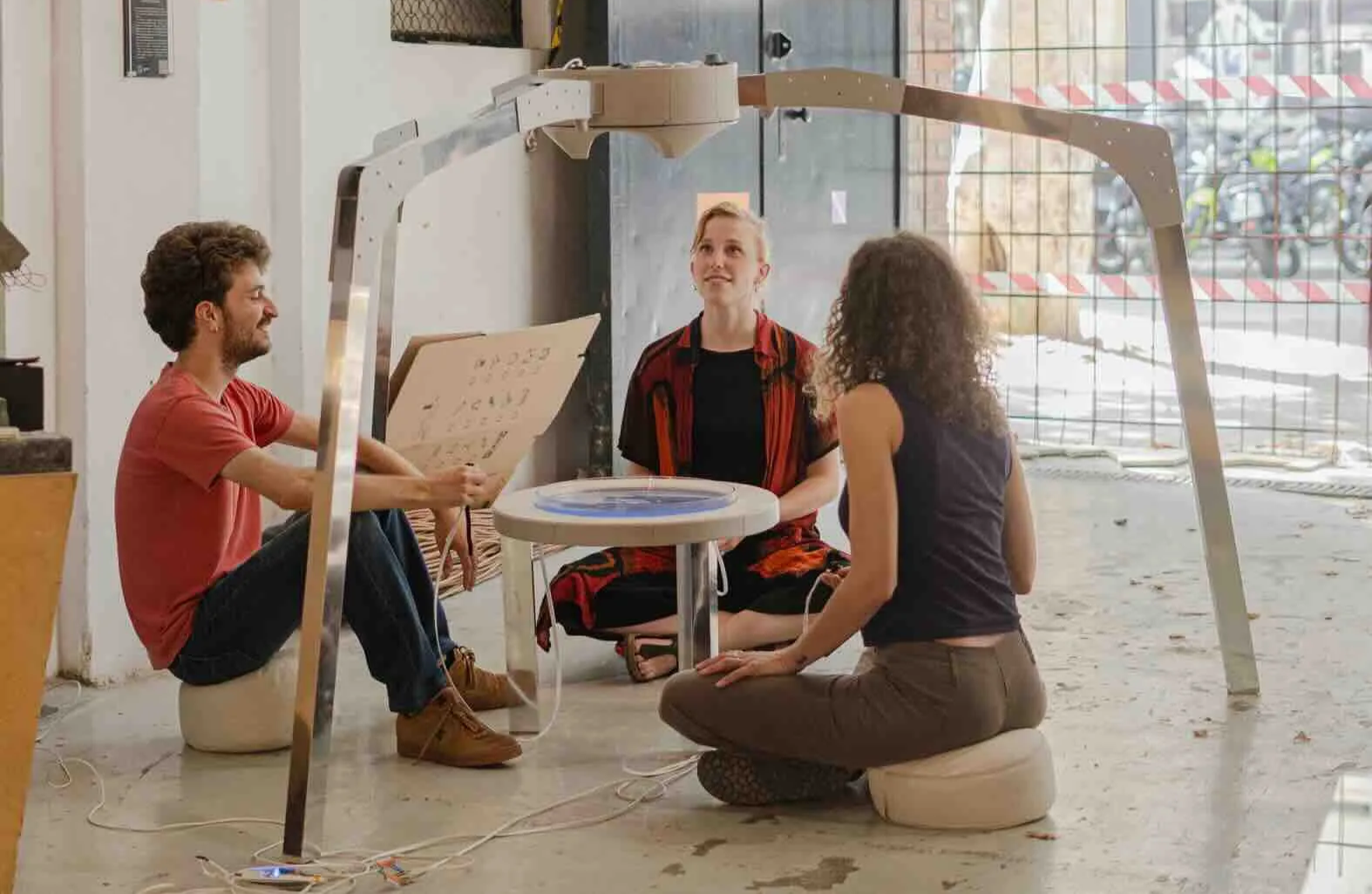
At its heart, Basin is a work created for communal meditation. The aim of the work is to nudge the three users into a state of mental focus and physical self awareness. The work aims to do this by taking in biofeedback (heart rate or respiration) from the 3 sitting participants and visualizing this data as droplets of water. Basin intends to be a counterpoint to the design philosophy of popular social media platforms. I and many others have felt a growing unease with the way social media captures and manipulates our attention, often promoting a feeling of unrest, loss of agency, and disembodiment. Thoughtful criticism on the effects of social media are plentiful and thus I don’t feel more is needed. Thus, the purpose of Basin is to offer an antidote and a source of inspiration for the many ways attention technologies could be created to reconnect to our sense of agency, our physical bodies, and our community.
Technical Overview
Basin can be thought of as 3 control systems the lower (sending system), the upper (receiving system), and the lighting system. Below is a breakdown of how these systems interact in the work.
- The lower control system PCB is identical to the upper system PCB just with different connections. It connects 3 sensors over UART that either sample heart rate or respiration (depending on if pulse-ox or mm wave is used). These sensors are read and interpreted using a rolling average to smooth the incoming data. The resulting reading from the three sensors are then divided by three and then processed into a single line with their identifier to be sent to the upper control unit over serial /UART.
- The upper control system reads the incoming serial line and processes the values as PPM to be sent to the correct peristaltic pump dispenser.
- The lighting systems is just that, a very basic +12v lighting system running on a separate power rail and dimmed by decreasing the voltage on its supply converter.
01—Research Artistic / Conceptual
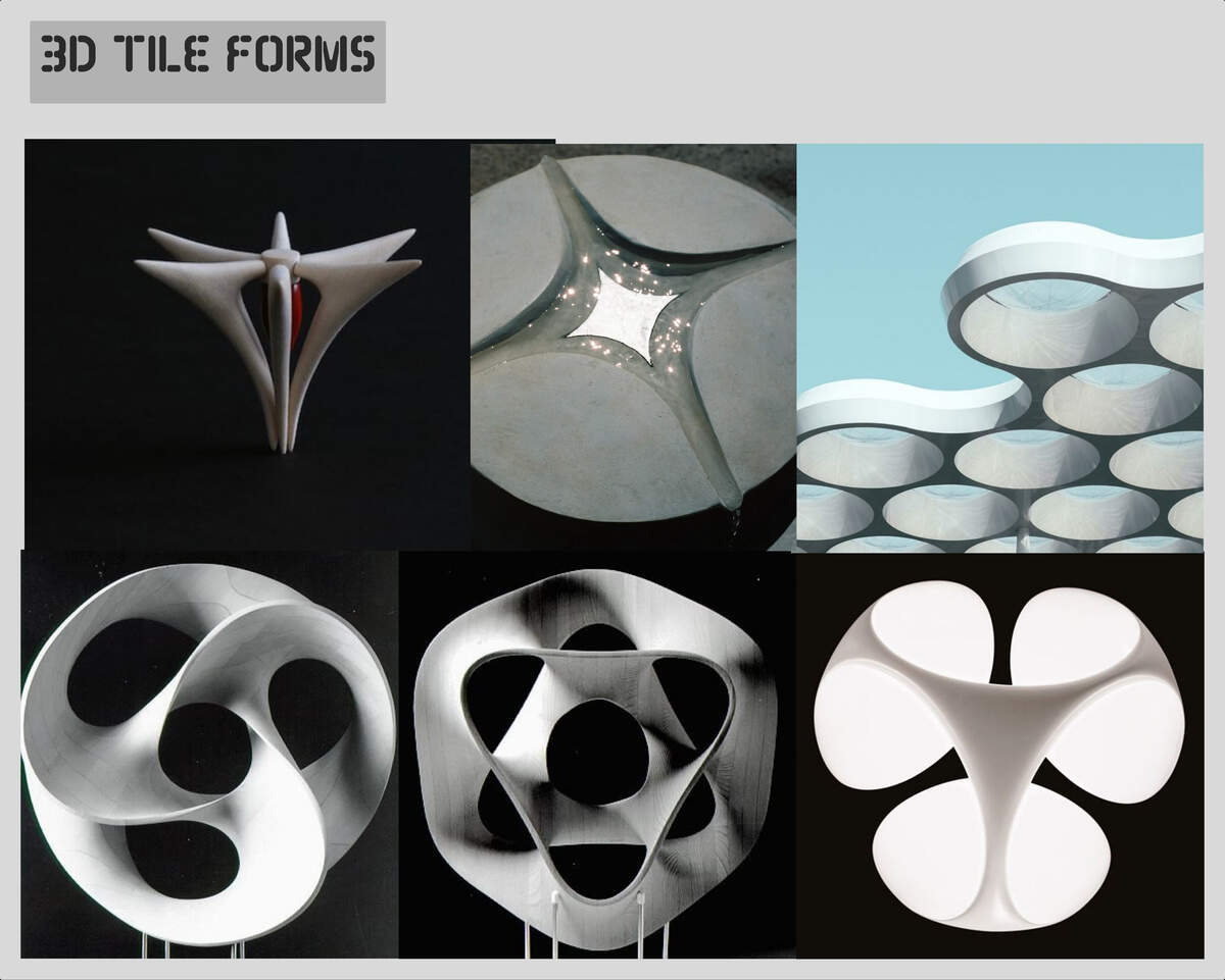
About section: Visually the work needs to draw attention towards it primary elements. These elements are the dish at the center and the caustic shadows it produces. For this reason the visual references I have chosen have very clear focal points, use a limited color pallet, and often use materials that have a lot of mass like stone or stainless steel.
Artistic References
Similar projects have been created and two of them are direct influences for my project visually and functionally. Below are my 3 major artistic influences:
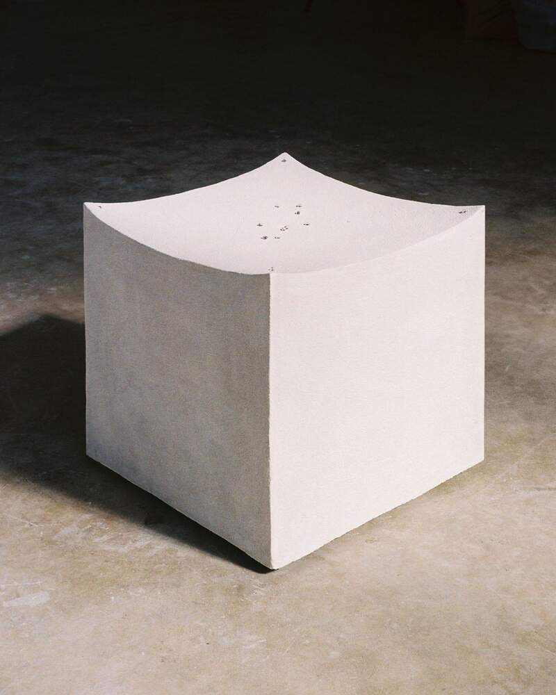
Objects for A Heavenly Cave—Lily Clark
Lily clark tends to work with stone and has great sense of proportion and composition that I have been strongly influenced by. Objects for a Heavenly Cave is very unique subtle work that I want to capture some of the spirit of in basin.
Passage to the Lake—Seop Peoseo
Passage to the Lake is a very refined piece that uses a very similar mechanism to what I would need for my work. His piece is based around a peristaltic pump system.
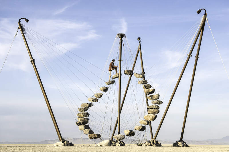
Stone 27— Benjamin Langholz
Stone 27. Ben’s work has a lot of visual impact. I appreciate how he keeps his work focused focused visually and participatory.
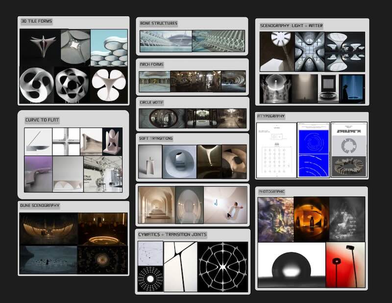
Visual Concepting and Mood Board
The forms I find myself more drawn to are summarized in simple words below. The form I am looking for should be confident, but quiet mixing defined lines and flat planes with organic curves.
- Disney’s Andor Season 2: The set design particularly of the planet Ghorman is incredible complex organic forms balanced by angular guiding lines are seen throughout.
- HBO’s Dune Prophecy: The set design in this show is also amazing. Many scenes use water as a motif and often play with cymatics + water
- Hard to soft transition form in of white that blend stepped geometry
.jpg)
.jpg)
.jpg)
.jpg)
.jpg)
.jpg)
.jpg)
.jpg)
.jpg)
.jpg)
Pre-visualization
The below were two early to figure out the composition and size of the project. I later moved onto a similar triangular configuration as seen in the image on the right, but with a decreased height.
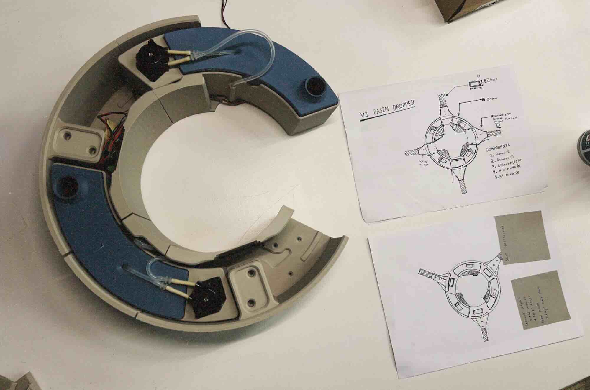
First Prototypes
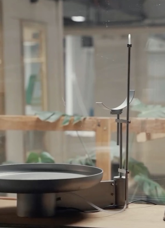
Below was a simple one dropper 3D printed prototype to test out the functioning of the full dropper system. I experimented with lighter fluid and dyes to see if they made sense for the final piece.
02— Electronics Dev & Code Dev
Initial Component Research
About section: Below are a few of the component I researched for my final design
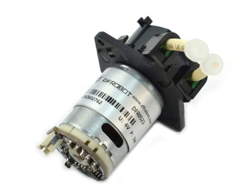
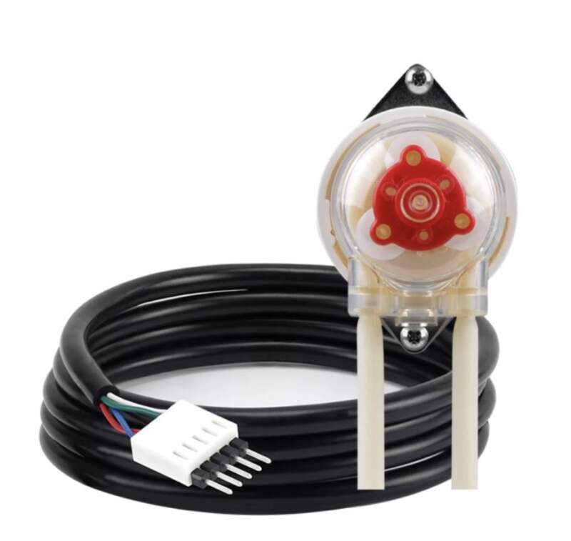
Peristaltic Pumps
DFRobot — PPM Peristaltic Pump
- PPM controlled like a servo motor for easy software control
- Custom library and the ability to be calibrated
Atlas Scientific — EZ Pump
- Promising design great documentation
- Great I2C interface which making IO management on the Xiao much easier.
- 4 times the cost as the DFR pump.
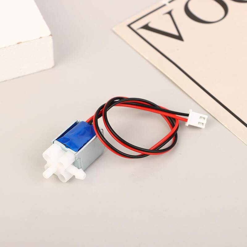
Solenoid Valves
Air solenoid valves
- Asumming adequate pressure valves like this air valves could have been used. The advantage could be reduced noise.
- Wear on element could be higher than the pumps.
- The change in water pressure could impact accuracy substantially.
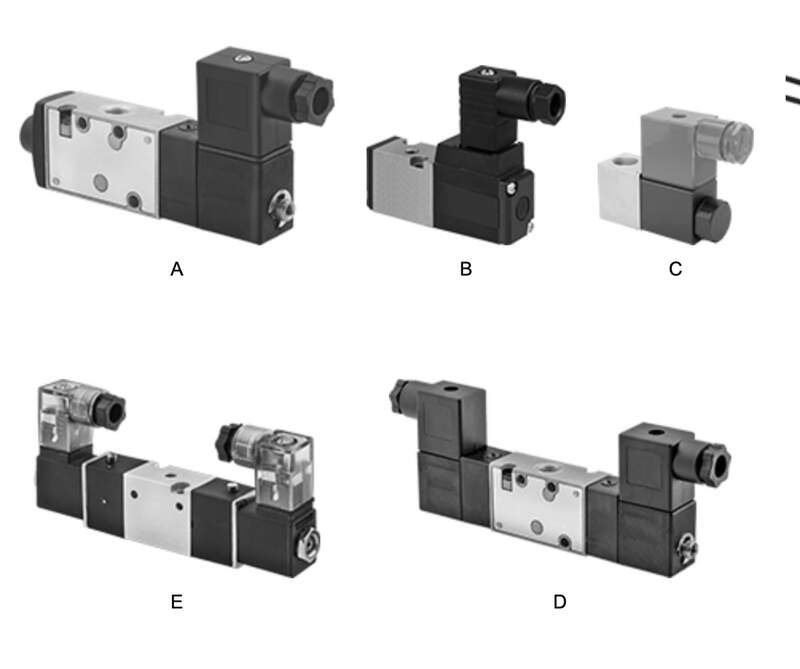
High Performance Cartridge Style Valves
- A lot of product differentiation in this space and I don’t know the first thing about these. This cartridge style seems to be common in industrial automation. I have also seen them used on high end large format printers.
- Theoretically could be a major improvement over the simple solenoid valves as these are designed with accurate dosing in mind.
- Price is unknown
The Xiao C3
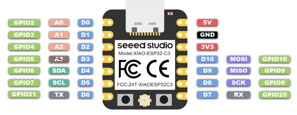
The Xiao C3 and the C6 were considered because I was familiar with their platforms the xiao C3 ended up be chosen because is a bit more compatible than the C6 which is newer more expensive and had features I did not need.
At a glance
- Connection type Grove I2C 3.3 or 5V
- vcc = 3.3V or 5V
- Max W = .5 (for 4) = 2 W
Key Specs
- Human Static Presence Detection: up to 6 Meters
- Breathing and Heartbeat Detection: 1.5 Meters
- WS2812 RGB LED (neopixel) onboard
- Sensor will get best reading pointed at chest
Code Dev— All about spirals
After many small software experiments over the first several months I set out to develop the full working code using what I had learned. From my learnings I had determined that it was far easier break up the project into many discrete parts a verify the full function of each code block. Since I was developing it using Ai coding agents (Gemini and ChatGPT) I spent a full day writing the descriptions for how the code should work. Below are the programs I developed discretely and later combined to create the first version of the two part sender / receiver control software.
multi_pulse_control
Overview: This program is written for the Xiao C3 connected to 3 DFR peristaltic pumps the program’s purpose is to control the rate and duration the pumps actuate when provided a run signal.
- Per Pump Pulse Control—control each pump independently. The control I need for each pump is the ability to take a number [max input = 180] that will dictate the number of pules the pump makes per minute (
pulse_pm).
- Global Single Pulse duration—All pump will have a global pulse duration that is set early in the program. This global pulse duration allows me to calibrate the pump actuation.
- Serial control for debugging— all 3 pump objects should be controllable through the serial console using serial commands written in the Arduino IDE. You should be able to call out a pump by its identifier and the number of pulses you want it to actuate with [0] being off. The status of each pump should be listed on a single line in the serial console and updated every second.
dfr_heart_sensor
Overview: This program is written for the the Xiao C3 connected to DFR MAX30102 pulse oximetry sensor over I2C. The purpose of it is to read and print values from this sensor to the serial console in Arduino IDE.
- The program should be able to read the sensor from its I2C bus and interpret the values for the heart rate variable using a rolling average method to reduce jitter in the data. The resulting values should be printed every 2 seconds to the serial console in Arduino IDE for debugging.
- The name of the sensor should be
heartsense_1as later the code will need to be expanded to accommodate 3 sensors (ieheartsense_2,heartsense_3)
- Heart rate value divider— I will need the option to globally apply a division operator to all heart rate BPM values the result of this will be called
pulse_pm.
test_receive and test_send
Overview: This program is intended to pass a value with an identifier from a board named ‘sender’ (Xiao ESP32 C3) to another board named ‘receiver’ (Xiao ESP32 C3). The goal is to confirm that the messages has been received and that the integrity of the message is intact. To do this the program should send the message over the default UART pins between the two MCUs [GPIO 21 TX GPIO 20 RX]. The baud rate for sending between the controllers can be very slow as a delay of 25ms from sender to receiver would be acceptable. More specific details are below.
- The value sent should be an identifier + value it should look like:
heartsense_1 pulse_pm ###heartsense_2 pulse_pm ###heartsense_3 pulse_pm ###. The number in each previously mentioned item is just a place holder value that can be randomly selected.
- I need to be able to confirm that the message has been received through the serial console
- Please be very careful to consider the specific MCUs I am using as well as the fact that I am using the latest versions of the Arduino IDE and Esspresif board packages and any included libraries.
v1_pulse_control_receive
- Combines test_receive and multi_pulse_control
v1_dfr_heart_sensor_send)
- Combines test send and dfr_heart_sensor
02— Build Log
About section: In this section I am summarizing important milestones in the development of the project Basin. Of course, much more could be written about each milestone as some of them represent weeks of work. If you want more info feel free to contact me!
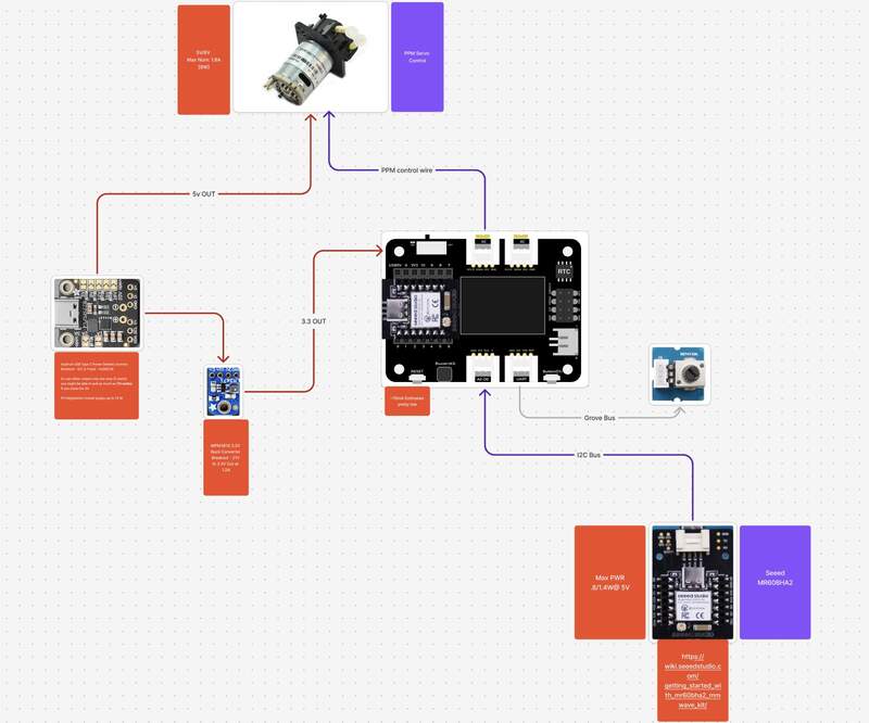
1— Initial Diagraming
This is my first attempt at at a scaled down version of my circuit. The final design will probably include 3 pumps and 3 sensors. I am using FigJam to keep track of all of the important specifications for the different devices.
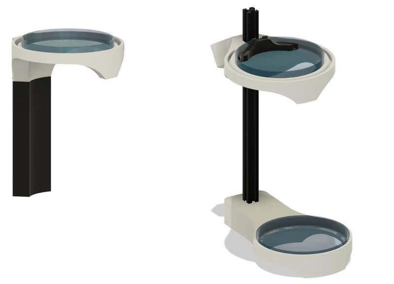
3— Initial CAD for Test Stand
On the left the first design on the right the second. I reworked it around a 2020 extrusion as I realized after I finished the first this was a better approach in every way.
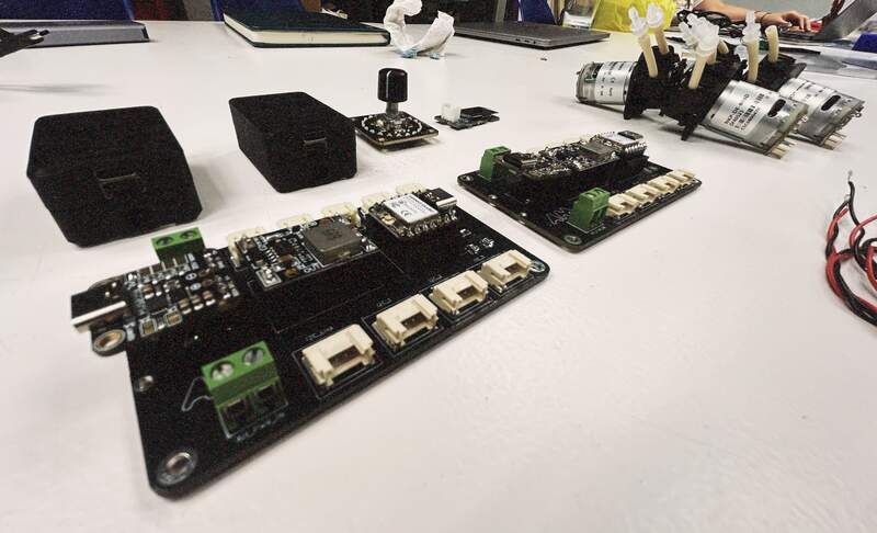
5— Basin Evaluation Board [v.5]
This was my first attempt at an integrated board that could power and run IO for Basin. It had to be scaled down to fit on single layer PCB so only 2 I2C inputs are present instead of the intended 3. The next version will be fully featured and many mistakes will be corrected.
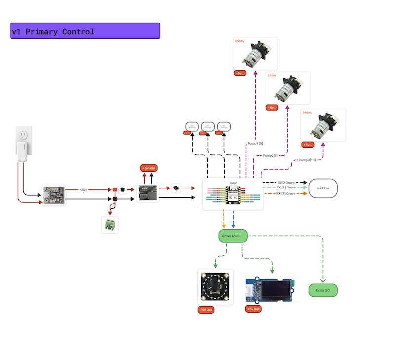
7— v1 Electrical Diagraming
This week I spent the last couple day diagraming researching parts for the two connected PCBs I am designing. More detail on the electronics selection will be added later as a separate section on the website.

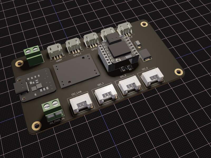
9— V1 Board Design in Flux
Getting to this point in with custom component in flux was hard won. This is just a rough layout I am mostly optimizing for legibility and space saving. I will be using a 4 layer PCB so I am not too concerned about routing, but likely things will need to be adjusted.
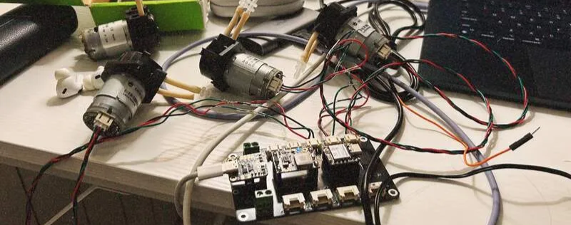
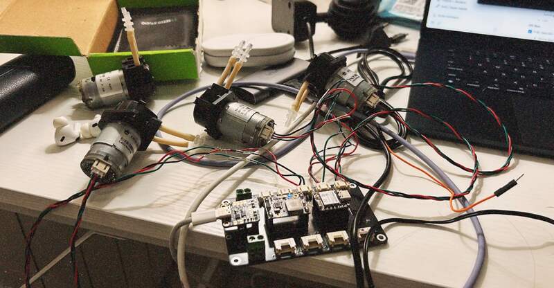
11—Assembled PCB
When I received the board I did the full component assembly. This was mostly painless, but as expected it took several hours to modify all of the prebuilt cable harnesses for my configuration.
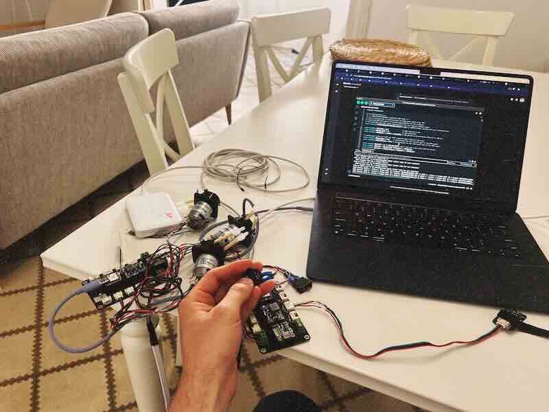
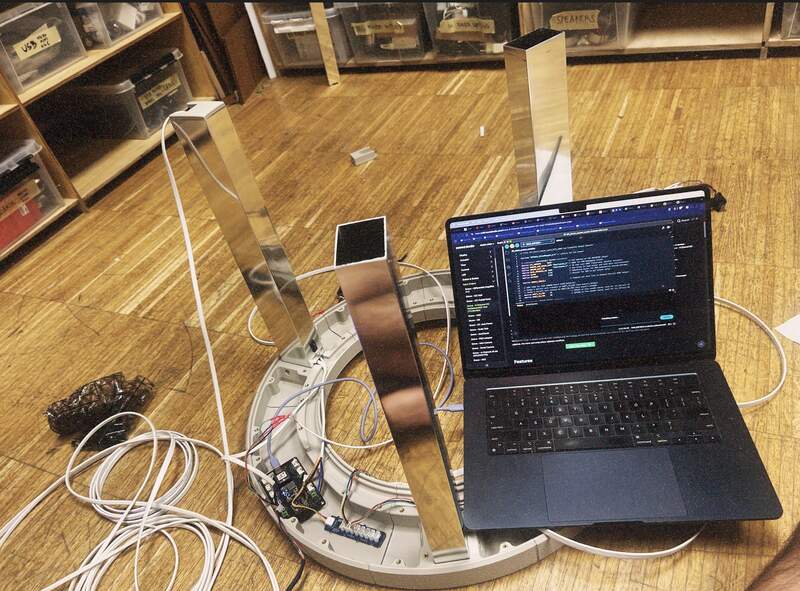
13—Full software integration
I was also pretty careful at this stage this took 2 long days. I worked intentionally slowly breaking the code into discrete sections and confirming they worked before advancing to the next feature. At the very end integrated all of the discrete programs and get the full software prototyped. More details about how I did this can be found here.
15— Photo / Inspiration Collection
I waited and waited to do this part. For me its actually easier to really understand the requirements of a project before I start playing with its form.
17— CAD Print CAD Print CAD Print
Over the course of about 3 weeks I designed the project as several distinct assemblies and at the completion of each assembly I printed it. All in all I had at least a 80 hours of modeling into the project. While I would have liked to design the whole thing then printed I did not have the time. So I printed things as soon as they were ready. The order for this was: lid, Reservoirs, Main chasis pieces, main basin pieces.
19— Main Assembly
Assembly was actually quite straightforward only amounting to about 2 to 3 days of work. Since much time was spent on the front end in CAD I caught I caught many issues in assembly (particularly nailing aluminum leg angles) early on. That said, mistakes were made 5 min epoxy was a bad call the premium Loctite CA glue was plenty strong and far easier to work with.
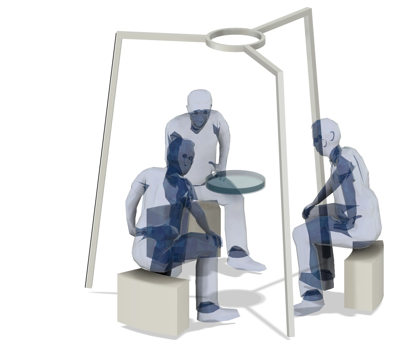
2— Initial Visual Concept
This was my first concept design for the project.

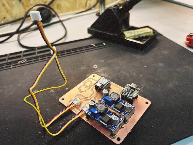
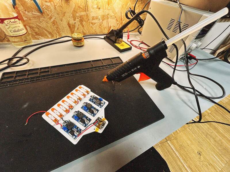
4— Voltage Conversion Jig
I have thought about creating something like this for a long time. Its just a set of buck converters se to different voltages powered by USB C PD enabling multiple easy to configure testing voltages.
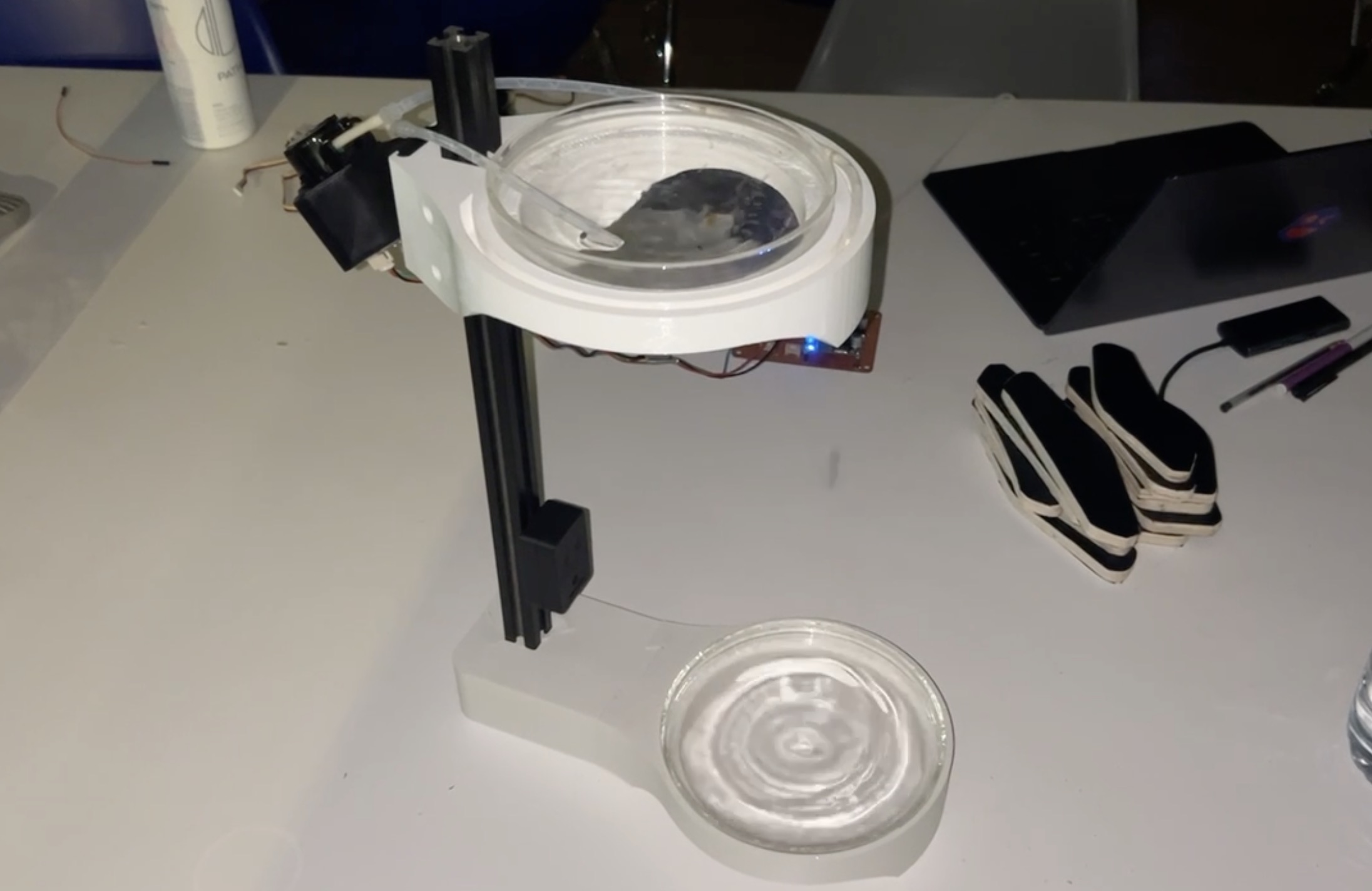
6— Initial Assembly and Dropper Testing
The design was then assembled and tested. The primary things I wanted to test were:
- The optical (caustic) effects I could get by shining a light at the water from different angles.
- If the dropper could reliably drop one droplet with minimal tuning and wether that effect was visually interesting
- The amount of splash at different heights

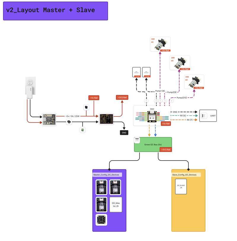
8— V2 Electrical Diagraming
This week I spent a lot of time researching and creating components. This resulted in minor edits to the diagram, but a lot of thought went into double checking components understanding I2C and the overall architecture. Crucially I realized that there was no need to create 2 different PCBs I added some small edits and Bam! I only need one now.
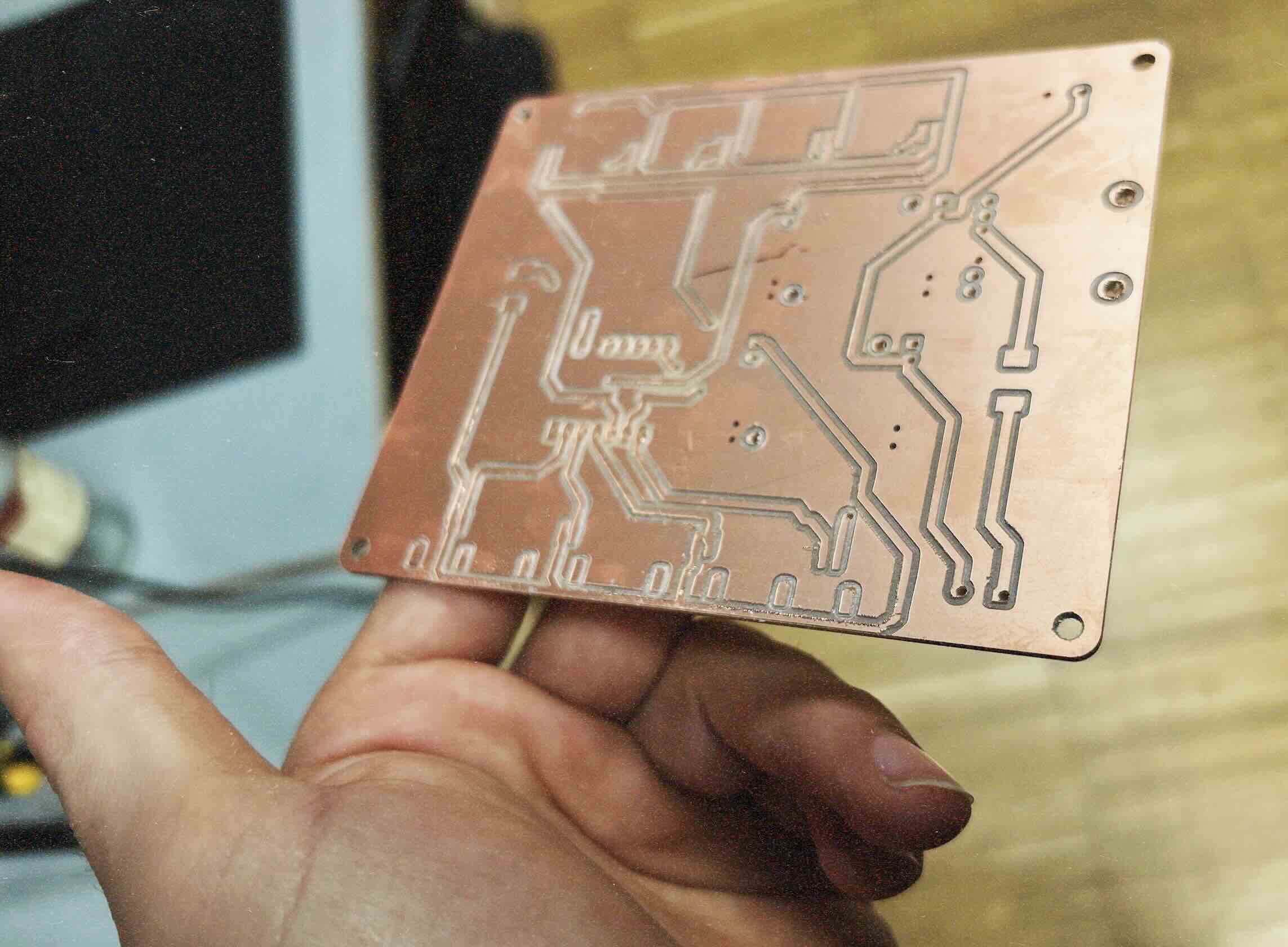
10 — Double sided Milled PCB
I was able to produce my double sided board to test before I sent in my board for production. This was an involved 2 day process. The milled board came out quite well, but I got busy and did not solder the components down. In the interest of time, I decided to pull the trigger on the production version of the board just in case.
12— Full board Test
The full system test took a day. I chose to be very careful and test and document the full board. I really wanted to separate hardware issues from software issues early on this way I would know for sure that the hardware itself was confirmed to work. Otherwise if the hardware had issues (it did) I knew about those issues before I got into the software Dev stage.
14 — Vibe Test
I experimented with many different options as for the dropper pool. I settled for this large cake dish. This was the largest straight wall glass dish I could find. When it arrived I did a quick test dropping water into it manually to see if my expectations matched the reality of how it looked. For the most part I was right, but actually the light created better shadows closer in and not further away from the dish.
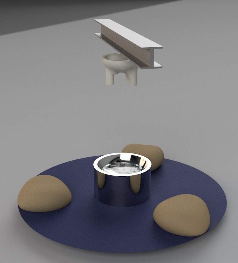
16— CAD Concepting
I spent a little more than a day working out just where to start with the project. I knew I was going to have 3 reservoirs and that the project was going to take the form of a circular chasis that was also a junction for the 3 legs. I played around with a tape measure to sort out the constraining dimensions for the design.

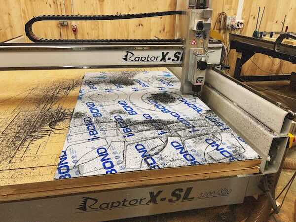
18 — CNC
Midway through the CAD design I decided structural plates would be needed to take the load off of some of the primary structure. This was also additional insurance to keep pieces that had bee split up into many separate components to stay joined together.
20—Basin Assembly
I ran into some issues when glueing the 9 basin sections together. I had accidentally reprinted a section and glued sections together in the wrong order. For this reason I am going to force myself to use an a part ID system printed into the parts.
03— Electronic and Structural BOM
Electronics BOM
*qualities listed below are needed to create the two identical custom PCBs needed for the upper and lower control system.
BOM: v1_Design (SENDER + RECEIVER)
%201c8d790de3e580b39914e14d9f92da9b/Adafruit%20USB%20Type%20C%20Power%20Delivery%20Dummy%20Breakout%20%201c8d790de3e5809e8887e51c79e1898c/CleanShot_2025-04-01_at_15.57.162x.jpg)
%201c8d790de3e580b39914e14d9f92da9b/DC-DC%20Multi-output%20Buck%20Converter%20(3%203V%205V%209V%2012V)%201c8d790de3e580a3afacd041c1ea85c7/CleanShot_2025-04-01_at_21.41.062x.jpg)
%201c8d790de3e580b39914e14d9f92da9b/Gravity%20Digital%20Peristaltic%20Pump%201c8d790de3e5802bb8b7fd059dd0e6c9/CleanShot_2025-04-01_at_15.44.332x.jpg)
%201c8d790de3e580b39914e14d9f92da9b/Gravity%20MAX30102%20PPG%20Heart%20Rate%20and%20Oximeter%20Senso%201c9d790de3e58064bd7fe0415a618ba0/CleanShot_2025-04-02_at_16.15.302x.jpg)
%201c8d790de3e580b39914e14d9f92da9b/XIAO%2060GHz%20mmWave%20Human%20Breathing%20and%20Heartbeat%20Se%201c8d790de3e5801492a8f47e398d0352/CleanShot_2025-04-01_at_15.44.192x.jpg)
%201c8d790de3e580b39914e14d9f92da9b/4%207%20kOhms%20%C2%B11%25%200%2025W,%201%204W%20Resistencia%20en%20microproc%201c8d790de3e580a8a337d8fb7ac00779/R0566046-06.webp)
%201c8d790de3e580b39914e14d9f92da9b/DIODE%20SCHOTTKY%2040V%201A%20DO214AC%20%5BSS14%5D%201c8d790de3e580f383b2e5dd55f5caa8/CleanShot_2025-04-01_at_15.52.512x.jpg)
%201c8d790de3e580b39914e14d9f92da9b/Rocker%20Switch%20SPST%2010A%20(AC)%20125%20V%20Panel%20Mount,%20Sna%201c8d790de3e580f98bf5e3c8724723bc/CleanShot_2025-04-01_at_15.44.092x.jpg)
%201c8d790de3e580b39914e14d9f92da9b/7%20Posiciones%20Cabecera%20Conector%200%20100%20(2%2054mm)%20Orif%201c8d790de3e580298273d1871d9947c8/CleanShot_2025-04-02_at_17.42.472x.jpg)
%201c8d790de3e580b39914e14d9f92da9b/BUSOHE%20Cat%208%20Ethernet%20Cable%2010M,%20Flat%20Network%20Cabl%201c8d790de3e58075b37dc82a7c945d6b/CleanShot_2025-04-01_at_22.54.092x.jpg)
%201c8d790de3e580b39914e14d9f92da9b/2%20Position%20Wire%20to%20Board%20Terminal%20Block%20Horizontal%201c8d790de3e580309baed55590818aa2/CleanShot_2025-04-01_at_15.45.082x.jpg)
%201c8d790de3e580b39914e14d9f92da9b/GROVE%20CABLE%204POS%2050CM%202PACK%20%5BA034-C%5D%201c8d790de3e5800c9c61ea3530cf0944/CleanShot_2025-04-01_at_22.01.582x.jpg)
%201c8d790de3e580b39914e14d9f92da9b/Gravity%20Digital%20Sensor%20Cable%20for%20Arduino%20-%2050cm%20(1%201cdd790de3e580919f3eccc59aba4d9d/CleanShot_2025-04-06_at_22.08.022x.jpg)
%201c8d790de3e580b39914e14d9f92da9b/CONN%20HEADER%20VERT%203POS%202%2054MM%201c8d790de3e580bdb3b1c2d18b5fe7b0/CleanShot_2025-04-01_at_16.09.342x.jpg)
%201c8d790de3e580b39914e14d9f92da9b/CONN%20HEADER%20R%20A%203POS%202MM%20%5BS3B-PH-SM4-TB%5D%201c8d790de3e580199b56df89ae2f7377/CleanShot_2025-04-06_at_21.54.542x.jpg)
%201c8d790de3e580b39914e14d9f92da9b/GROVE%20FEMALE%20HEADER%20R%20A%2020PACK%201cdd790de3e58001a241f454fbc45b3e/CleanShot_2025-04-06_at_22.02.342x.jpg)
Structural BOM
Structural BOM (1)
Project Files
Below (control code, Bambu print files, and flux.ai PCB file)*
*please note due to the file size CAD files are not included in the zip below. I am happy to provide various 3D project files upon request.
License