Simulation - Wokwi
you can find the link to the group work here
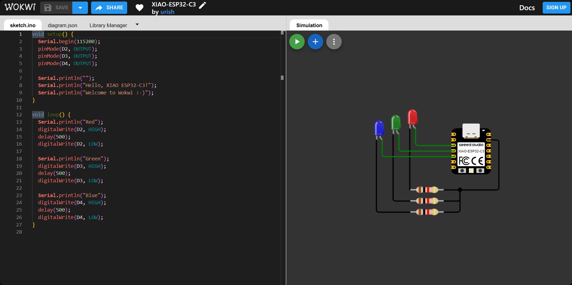
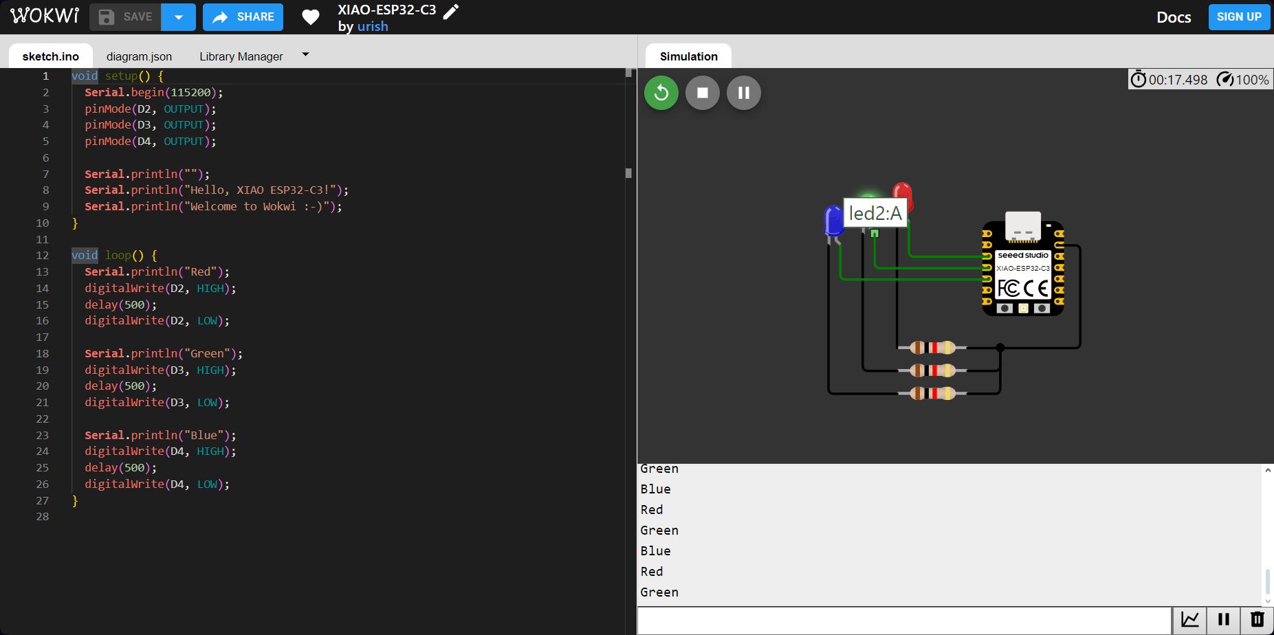
Wokwi provides built-in libraries that simplify the coding process by enabling interaction with various components like LEDs, buttons, and microcontrollers. In this project, I used the Seeed Studio XIAO ESP32-C3 microcontroller to control three LEDs (Red, Green, and Blue) via GPIO pins.
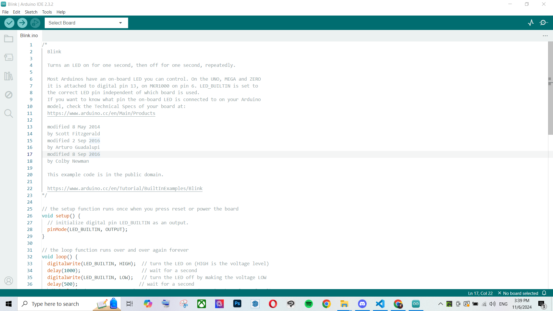
Here I changed the duration in between each blink, you can see the delay takes alot longer than the pevious code, exectedly.
Embedded Programing - Adafruit
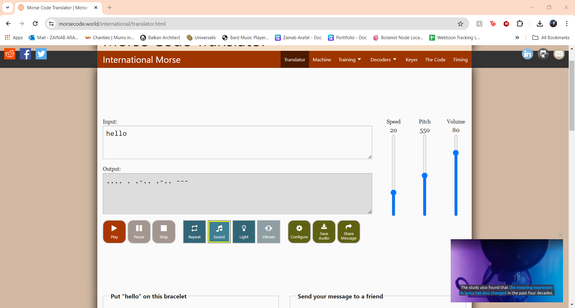
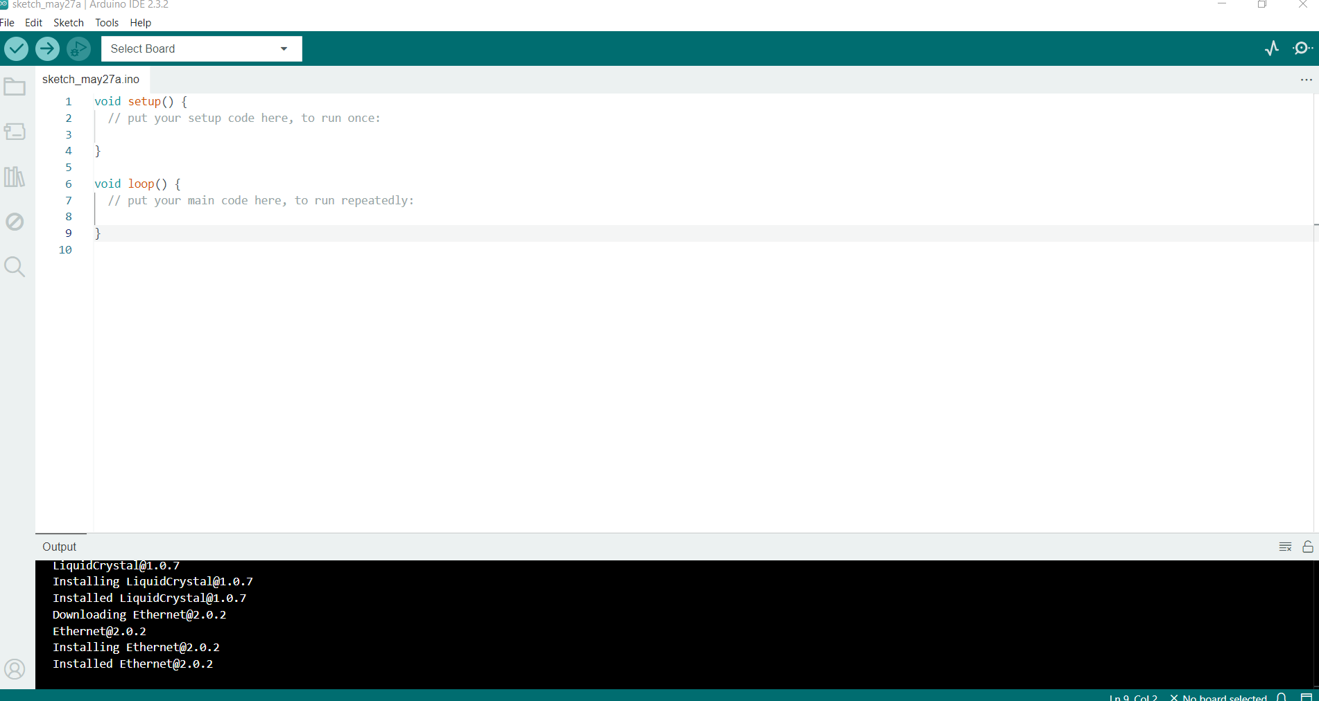
For this week we were using arduino ide to code, we started with using a preprogrammed sketch to code morse code into the microcontroller.
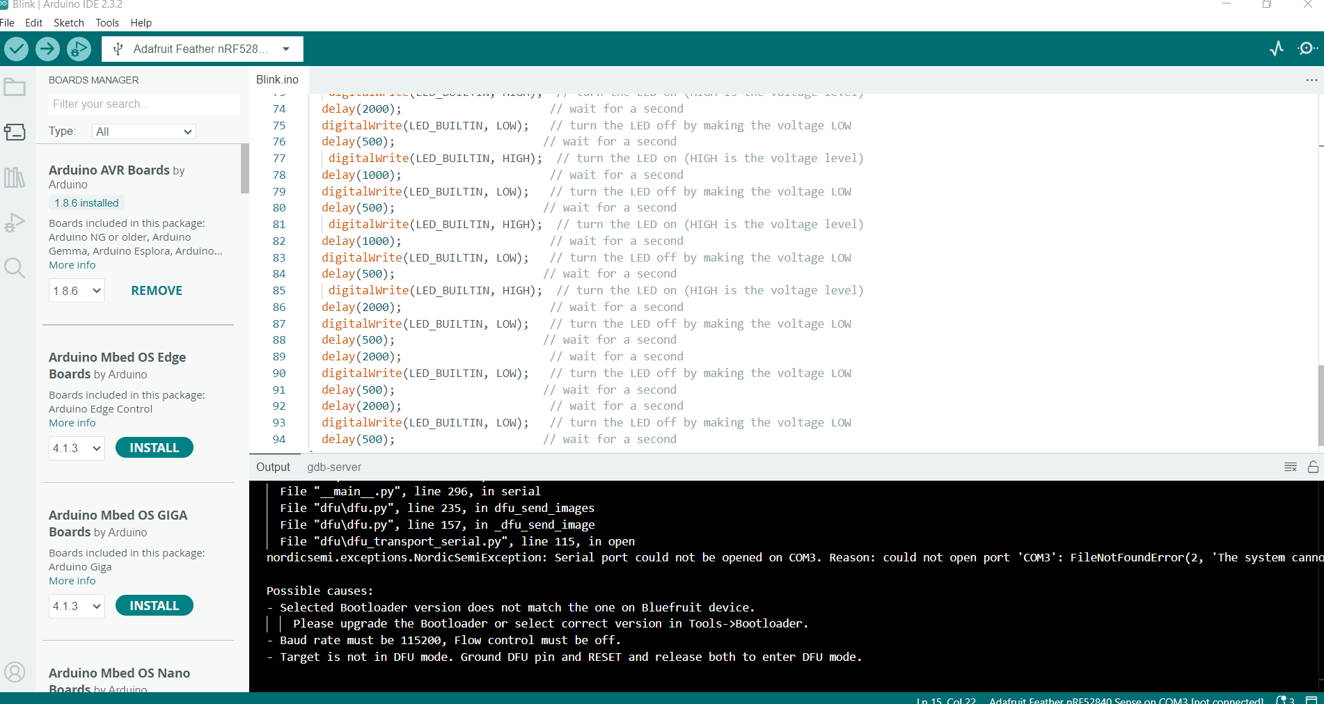
The microcontroller I'm using is adafruit microcontroller, Adafruit IO is a system that makes data useful. Adafruit microcontrollers often include built-in sensors, LEDs, and connectivity options like Wi-Fi, Bluetooth, or USB, making them ideal for applications ranging from IoT projects to wearable devices.
after plugging the microcontroller into using a usb cable, in order to turn it on and be able to put the code in it, double clicking a button on the microcontroller itself is important.
ೃ⁀➷Processor: ESP32-D0WDQ6, dual-core Xtensa LX6, 240MHz, 520KB SRAM, 4MB flash.
ೃ⁀➷Power: 3.3V operation, USB or 3.7V LiPo battery with charging circuit (500mA max).
ೃ⁀➷ Connectivity: Wi-Fi (802.11 b/g/n), Bluetooth (BLE and Classic).
ೃ⁀➷Pins: 21 GPIOs, 8 ADC (12-bit), PWM, I2C, SPI, UART, I2S, touch sensing.
ೃ⁀➷Size: 2.0" x 0.9" (50.8mm x 22.9mm), ~5.6g.
ೃ⁀➷ Extras: User LED, FeatherWing compatible.
ೃ⁀➷Programming: Arduino IDE, ESP-IDF, CircuitPython.
After translating the morse code into a website, the symbols were then translated into the code by trasnlating it into high and low outputs. While changing the time between each blink, the code understands low as no light output and high as light output