The bending bench
Final project summary
Final project video
Final project
What does it do?
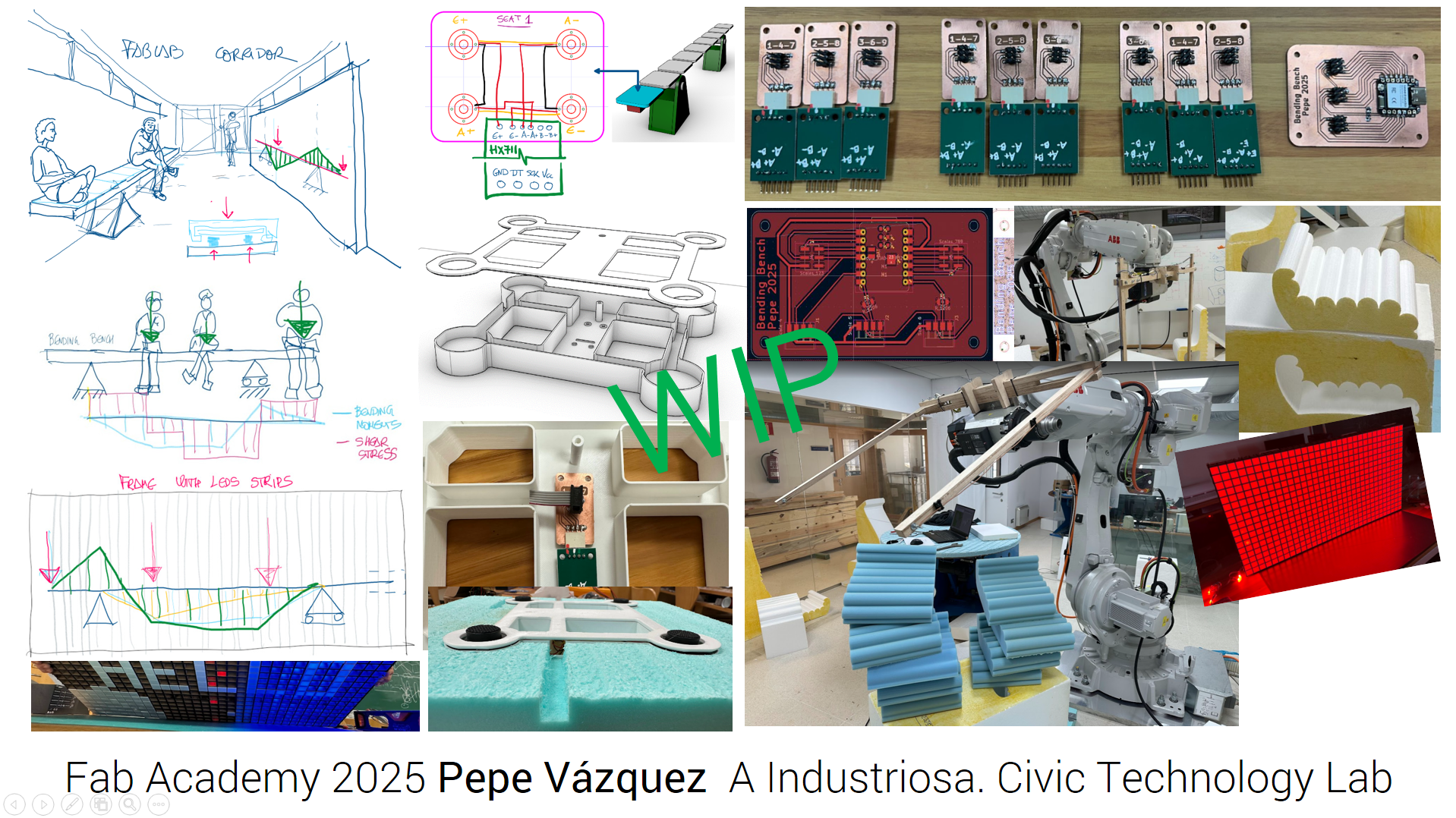
My final project is an educational proposal that enables real-time visualization of the bending moment diagram of a simply supported beam with two cantilevers. Each of the nine seats is equipped with a load cell that detects the weight of the person sitting on it and sends the readings via Wi-Fi to an LED matrix, where the structure’s bending moment diagram is displayed.
Who has done what beforehand?
I have not seen anything quite like my proposal. However, I drew inspiration from specific aspects of several previous projects: Augusto Mantilla (2024) with his smart dog house, Sophia Döring (2024) with a test bench for artificial muscles, and Svavar Konradsson (2023) who used multiple HX711 sensors. I also based parts of the LED visualization system on projects by Dorian Somers, Nadieh Bremer, Graham Smith, and Vishnu Raj.
What did you design?
I aimed to design and fabricate as many components as possible. I designed the full wooden structure, foam seats cut with hot wire, 3D-printed enclosures to protect electronic components, and the PCBs using KiCad (including HX711 + ESP32-C6). I also designed and laser-cut the panel housing the 17x32 LED matrix for visualization. The entire electronic and control system was designed from scratch.
What materials and components were used?
- MDF, solid wood, PLA, foam, screws, wiring
- 9 load cells with HX711 amplifiers
- 550 WS2812B LEDs with a 5 V 12 A power supply
- 1 Seeed XIAO ESP32-C3 and 1 ESP32-C6
- Custom PCBs
Where did they come from?
Most materials came from the Fab Lab inventory. MDF and specific tools were sourced locally (BricoSada, Cetronics), and the electronic components were purchased from Aliexpress and Amazon.
How much did it cost?
The total estimated cost of the project is around €550–600. Main expenses include:
- LEDs: €126
- Power supply: €32
- Load cells + HX711: €41
- Wood and brackets: €287
- Additional electronics and PCBs: ~€40
BOM
Hardware
| Items | units | description | € | total € |
|---|---|---|---|---|
| Load cell | 9 | 4x50 kg Load Cell 50kg Weighing Sensor Half-bridge Strain Gauge Human Body Scale Weight Sensor + mounting bracket + HX711 | 4,59 € | 41,31 € |
| LEDs | 11 | 50 Uds DC 5V WS2811 | 11,49 € | 126,39€ |
| Power Supply | 1 | LPV-100-5V 12A 230x70x40 mm | 32,62 € | 32,62€ |
| Lever quick connector | 20 | 1x2 32A | 0,44€ | 8,80€ |
| Bicolor Parallel cable OFC TASKER | 2 m. | 2 x 2,5 mm | 2,42€ | 4,84€ |
| Colored heat shrink tube | 2 | BPC0018 1,22 m d4,8 mm | 1,97 € | 3,94€ |
| Frame MDF 5 mm | 1 | 1210 x 1010 | 27,52€ | 27,52€ |
| 2 | 1000 x 800 | 22,11€ | 44,22€ | |
| Support | 2 | 1000 x 800 | 25,78 | 51,56€ |
| Beam | 1 | 4000 x 140 x 90 | 63,00€ | 63,00€ |
| Board under seats | 9 | 400 x 300 x 12 | 6,5€ | 58,50€ |
| Foam blocks for seats | 5 | 450 x 450 x 370 26kg/m3 | 29,16€ | 145,80€ |
Electronics
| PCB load cell | Quantity | Unit Prize |
|---|---|---|
| PinHeader_01x04_P2.54mm_Horizontal_SMD Data Sheet | 9 | 0,59€ |
| PinHeader_02x03_P2.54mm_Vertical_SMD Data Sheet | 9 | 0,55€ |
| Ribbon cable Data Sheet | 10 m | 10,30€ |
| PCB control load cell | Quantity | Unit Prize |
|---|---|---|
| R_1206 0 Ohm RC1206FR-070RL Data Sheet | 1 | 0,09€ |
| XIAO-ESP32C3 Data Sheet | 1 | 4,39 € |
| PinHeader_02x03_P2.54mm_Vertical_SMD Data Sheet | 3 | 0,55€ |
| PCB control LEDs | Quantity | Unit Prize |
|---|---|---|
| XIAO-ESP32C3 Data Sheet | 1 | 4,39€ |
| SCHOTTKY 100V 1A Data Sheet | 1 | 0,18€ |
| PinHeader_01x03_P2.54mm_H_SMD Data Sheet | 1 | 3,04 € |
| Input GND SM99S01VBNN05G7 Data Sheet | 1 | 0,88€ |
| Input 5V SM99S01VBNN05G7 Data Sheet | 1 | 0,88€ |
What parts and systems were made?
- CNC-machined beam structure
- Laser-cut LED matrix frame
- Foam seats
- 3D-printed enclosures
- Data acquisition and control PCBs
- Wireless communication and LED visualization system
What processes were used?
Parametric design (Rhino + Grasshopper), large-format CNC milling and robotic arm machining, robotic hot wire cutting, laser cutting, 3D printing, soldering, PCB milling, microcontroller programming with KiCad, and complete system assembly and integration.
What questions were answered?
- Can multiple load sensors be synchronized with a shared clock line? Yes, it’s important to stagger the readings from each load cell to allow enough time for each one to complete properly,in my case, I’ve done it using millis.
- Is real-time communication between two ESP32s stable? Yes, I haven’t detected any issues in the communication between the two MCUs — it has remained stable at all times.
- What level of accuracy and robustness does the structural system offer? The system ensures the structural safety of its components by incorporating an appropriate safety margin.
What worked? What didn’t?
The load cell readings, LED visualization, and mechanical structure worked correctly. The main issue was the CNC power supply failure, which forced me to fabricate the beam supports and panels using the robotic arm—a challenge that turned into a positive learning experience.
One of the most problematic aspects was rounding and remapping the bending moment diagrams to the matrix, since the nine load readings had to be represented across 30 of the 32 matrix columns.
How was it evaluated?
Evaluation was based on the following criteria: complete functionality, stability under expected loads, quality of design and fabrication, clear documentation, and especially its pedagogical usefulness for early-year students in technical fields.
What are its implications?
This bench provides a tangible educational tool for teaching structural concepts. It demonstrates effective integration of mechanics, electronics, and programming within a Fab Lab, and it is replicable for pedagogical use in architecture and engineering.
Licensing
I’ve decided to license my project under the Creative Commons Attribution-NonCommercial-ShareAlike 4.0 International (CC BY-NC-SA 4.0) license. This means that:
 Derivatives and adaptations of my work may be shared, provided they are distributed under the same license. This ensures that any modified versions uphold the same principles of openness and share-alike reuse.
Commercial use is not permitted, ensuring that the project remains accessible for educational, personal, and other non-commercial purposes only. This reflects my current goal of developing the project for personal use and documentation, with no immediate plans for commercialization.
My Final project summary
Initial idea
Project development
- Week 9
shared clock (CLK) signal implemented between load cells. - Week 10
scale configuration stored in the MCU using preferences. New PCB design includes external 5V power input. - Week 11
networwing and communications. WIFI. - Week 12
system diagram development. - Weeks 15-16
central PCB development, updated LED frame dimensions, 3D printing, laser cutting. LED frame assembled. - Week 17
PCB milling and component soldering for central load cell PCB and HX711 PCBs. LED installation, frame caps attached, and system integration testing performed. New seat design. - Week 18
hot wire cutting and milling processes. - Week 19
CNC milling, soldering, beam mounting. Initial test code for bending moment representation. Configuration and testing of bending moment diagrams.
- Week 9
System integration
Aplications and implications
Final project files
Acknowledgement
I would like to sincerely thank the research project ED431F 2024/17 funded by the Xunta de Galicia and led by Principal Investigator Pablo Guindos, as well as the excellence program BERCE (Code 00958), also under the direction of Pablo Guindos Bretones at the University of A Coruña, for their financial support. Their contribution made it possible for me to join the Fab Academy 2025.