Final Project Development
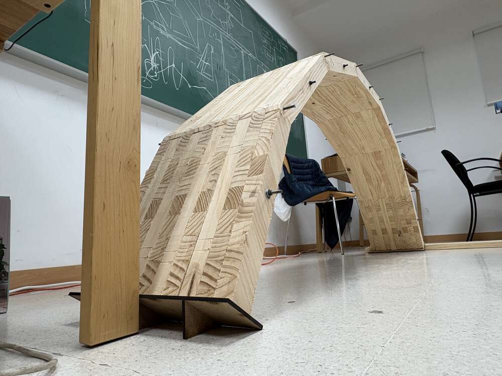
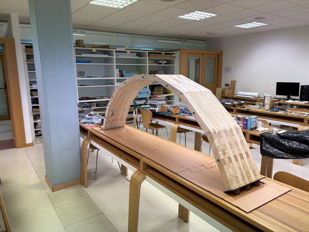
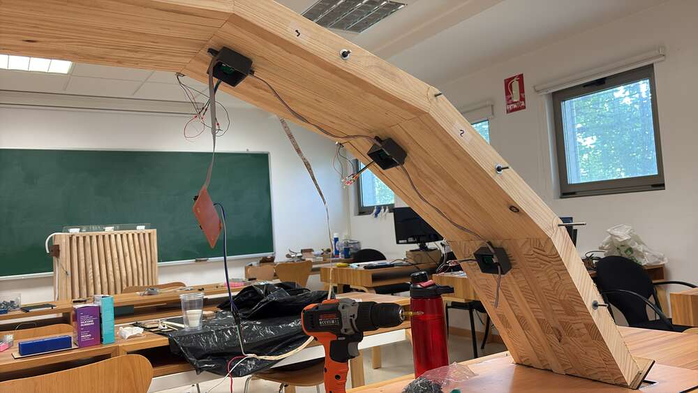
The project consists of building a self-assembling timber bridge made from small blocks with self-aligning joints that act as hinges. When suspended, the structure naturally takes the form of an arch. To monitor the structural performance of the bridge, load cells will be installed at key joints to measure the forces and loads acting on the structure. These sensors will provide real-time data on how the bridge behaves under different conditions.
In addition, the bridge will include a system of LED lights that visually communicate its structural health. The LEDs will change color depending on the load detected by the sensors. For example, under normal conditions the lights may remain white, while increasing load or stress levels will trigger color changes—such as red for critical states. This visual feedback system offers an immediate and intuitive way to understand the condition of the bridge without needing technical equipment or analysis.
week 3: CAD
On week 3 Of Fabacademy I sterted doing the final project knowing that it was going to be a lot of time and work.
For the initals of the project I thought about the geometry, I need to things in concrete:
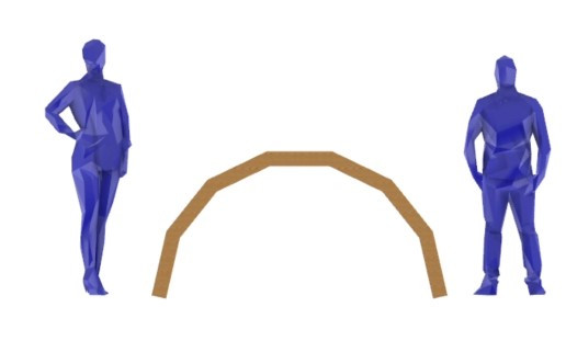
- It needed to be big enough to in the future can do mechanical tests to the structure with a considerable weight, that’s why I scale a tipical bridg
- It could not be so big because then work, move, tasnport, the assemble was to lavorious and we have limited time for the project.
- The perfect scale was 1:3 of a normal height mining it was which are normaly 2 m of span and 1/3 of height. 0,6 m.
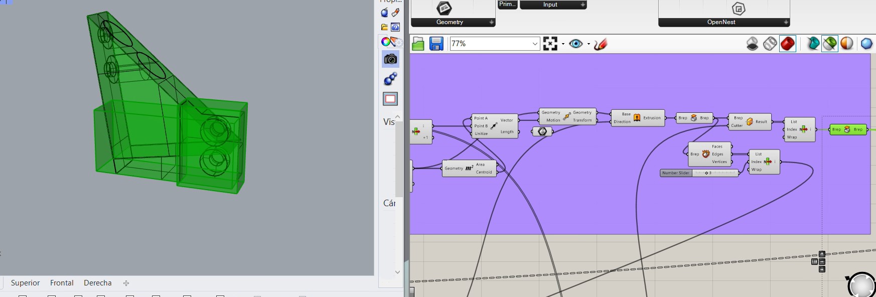
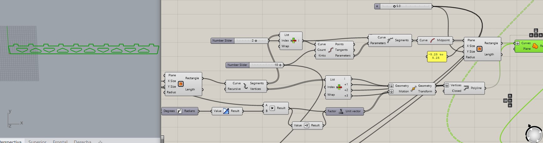
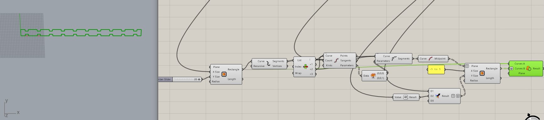
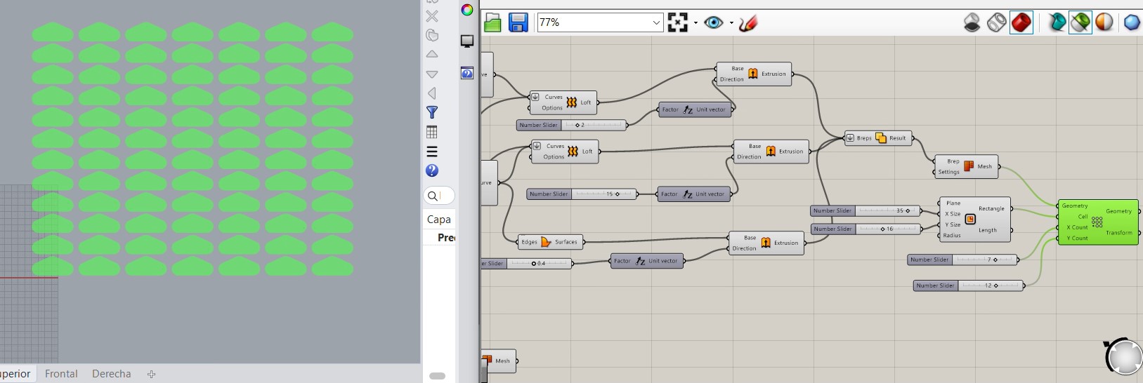
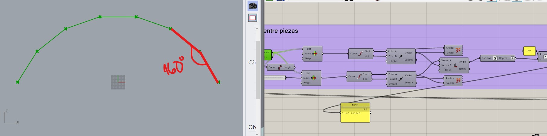
I did the design of the curve with Grasshopper so was all parametrized.
The code is the following:
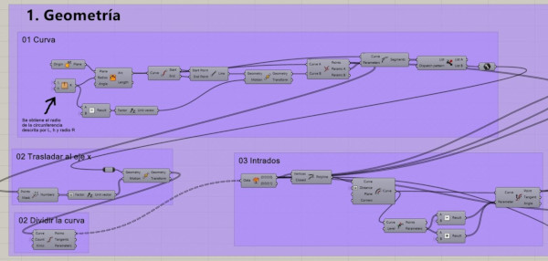
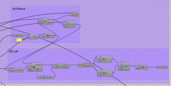
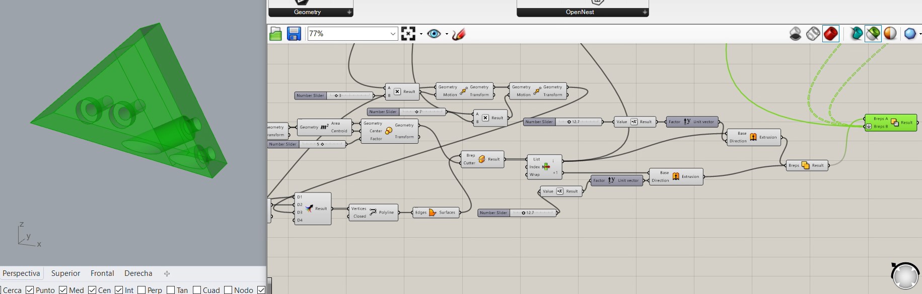
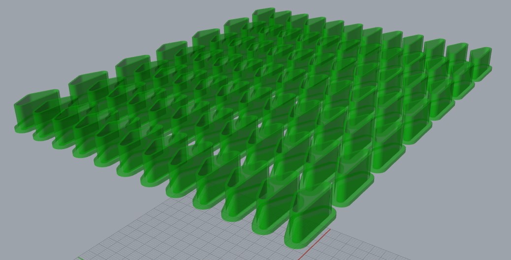
In the following image you can see the process of how the arch was constructed on grasshopper. NOtice that I divided the arch on 7 pieces.
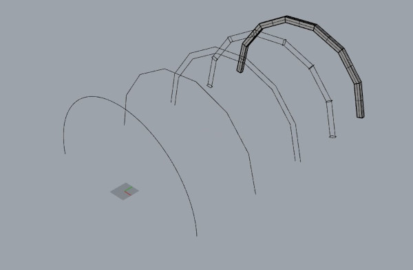
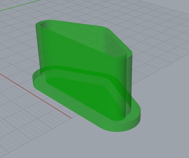
Finally it was going to look like this:
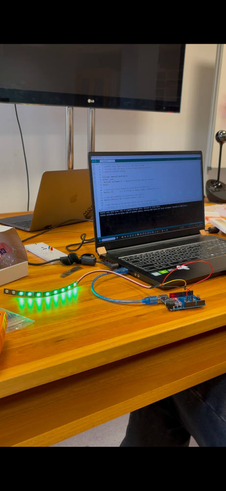
week 4: Embedded programming
This week I programmed and use different libraries for the led lights:
- Adafruit Neopixel
- FastLED
week 9: Input devices
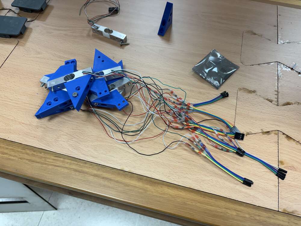
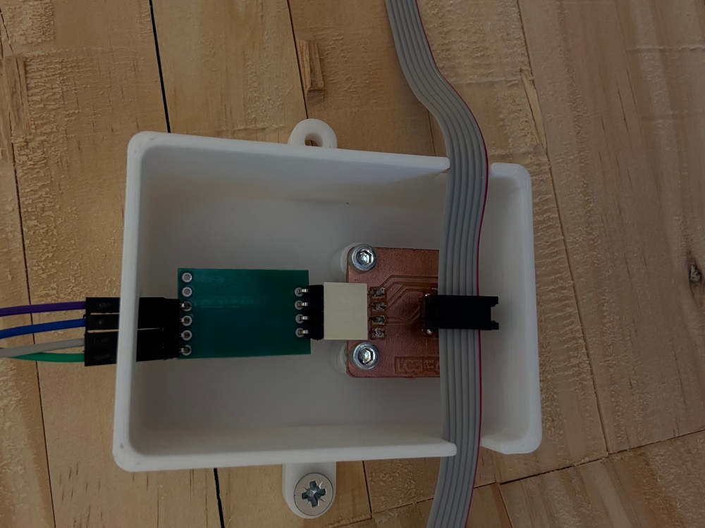
Then I had to connect the pins with cables for the communication of both components, The accelerometer use a I2C connection:
An I2C (Inter-Integrated Circuit) connection is a communication protocol commonly used in electronics to enable multiple devices to communicate with each other using only two wires: SCL (Serial Clock Line) -> Carries the clock signal that synchronizes data transfer. SDA (Serial Data Line) -> Transmits data between devices.
week 10: CNC
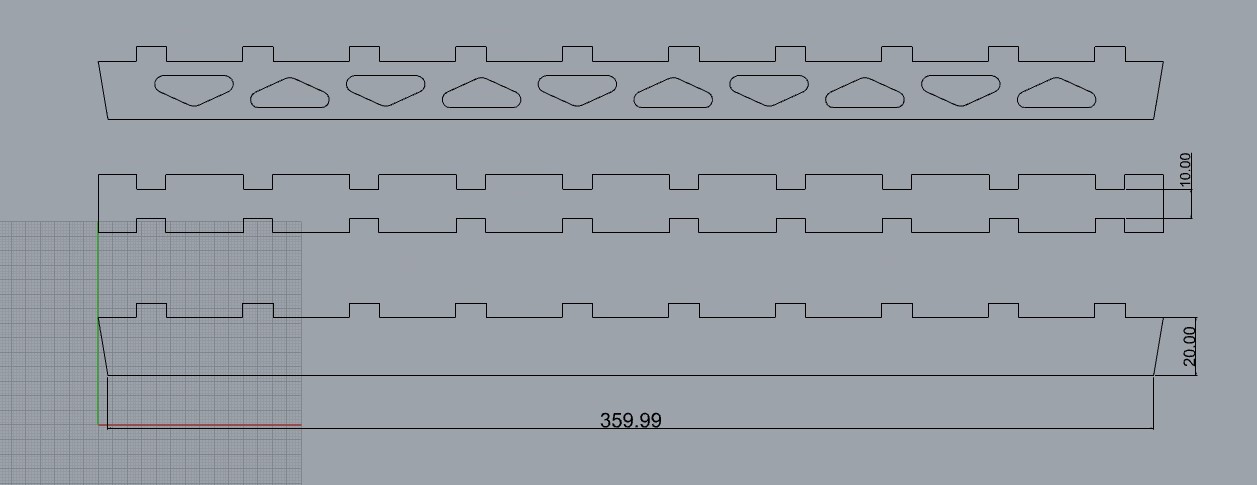
Once I had the pieces parametrized on grasshopper with the component of rhinoceros WireFrame I can take the siluete of the part and export it awith a .dxf file to Vcarve.
Once I had the work on Vcarve I decided that I was going to cut 9 boards of 1.22 m x 0.40 m
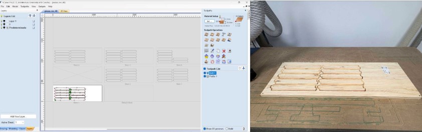
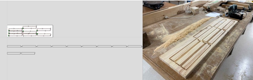
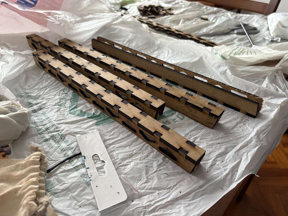
The process to take out the part of the part was a little bit laborious, because I had to break the support It had so when the machine is cutting the parts do not break off. I use carpintering tool to cut it.
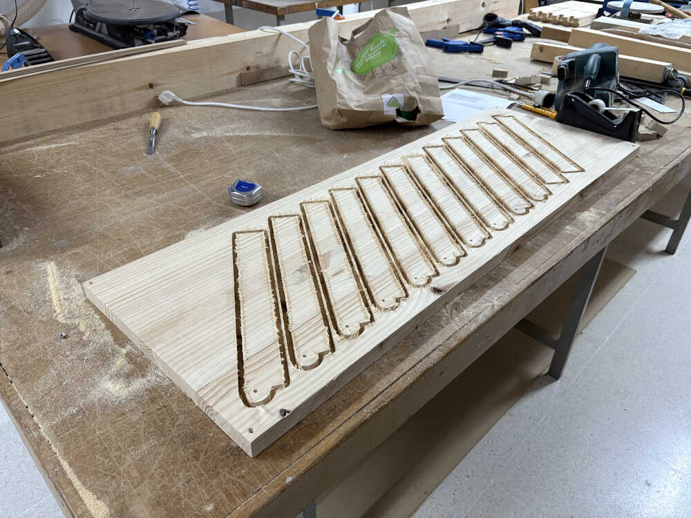
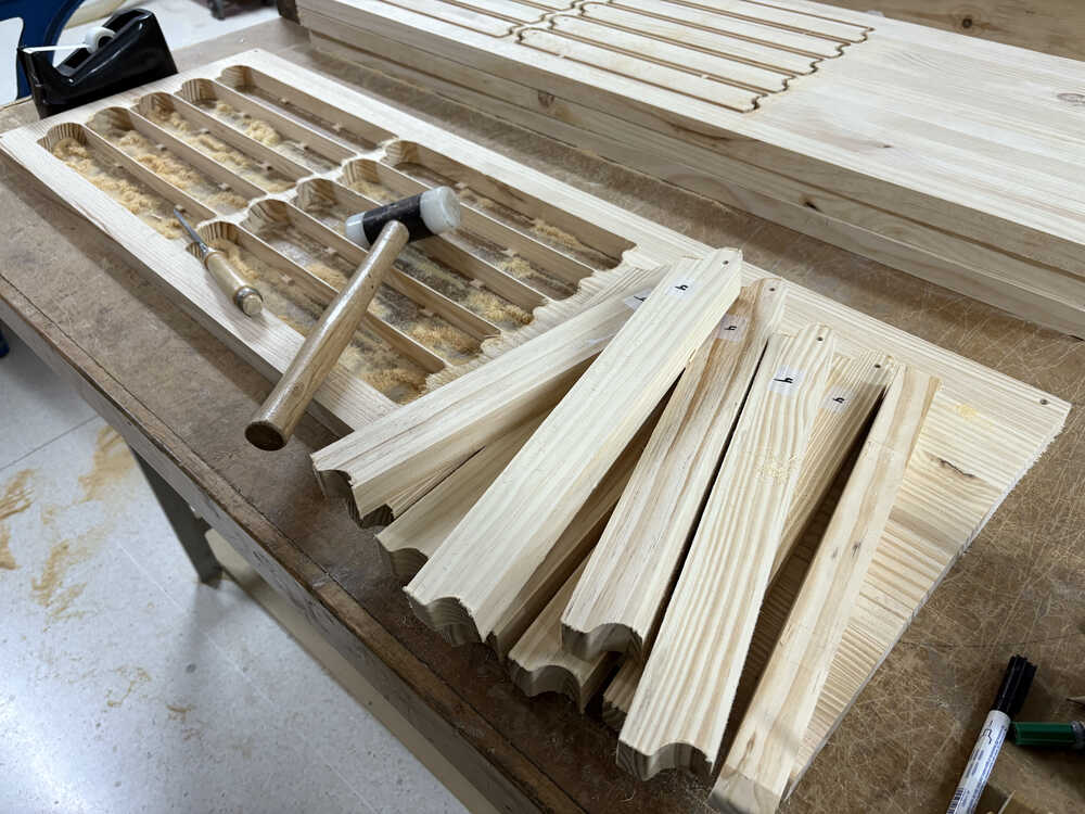
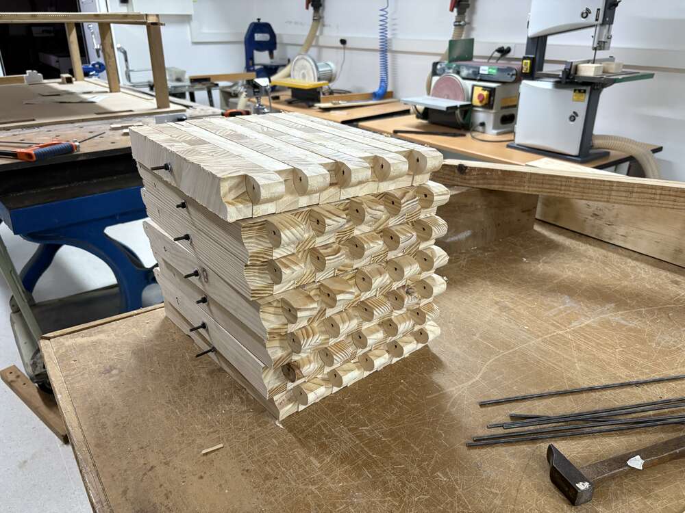
The firsts result of the parts you can look it on the following images, It is noticeable that that the precision of the machine is very very high.
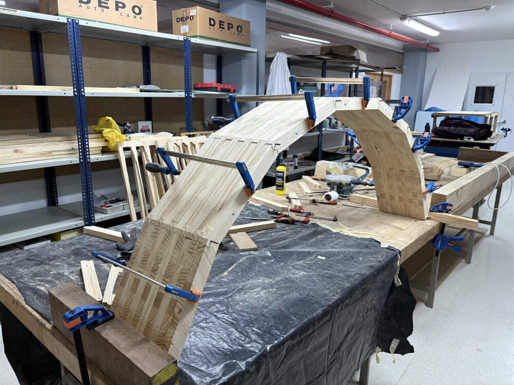
Once I had all the parts cutten I assemlbed and I used clamps to hold the structure in place while it lacks lateral stiffness.
week 12: Midterm Review
Diagram
Schedule for remaining task
| Month | Day | Days | Topic | Final Project |
|---|---|---|---|---|
| April | 21 | Mechanical design, machine design | Meet with local and global instructors | |
| 23 | 2 | Molding and casting | - | |
| 30 | 7 | Interface and application programming | Trip to Seville | |
| May | 7 | 7 | System integration | Design and produce pcbs, design the system integration |
| 14 | 7 | Wildcard Week | Do the moisture sensor, Programming the pcbs and mount the system | |
| 21 | 7 | Applications and implications, project development | Do the interface, data visualization and DLT + supports | |
| 28 | 7 | Invention, intellectual property and income | Do the presentation (video and poster) | |
| Jun | 8 | 11 | Weekly assignments deadline | Time for corrections and enhancement |
| 9 | Final project presentations | |||
| Total: | 48 | days remaining |
week 17: PCB design and production
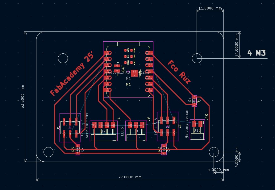
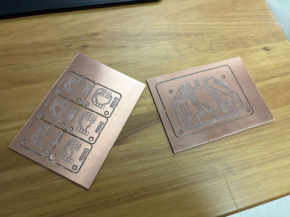
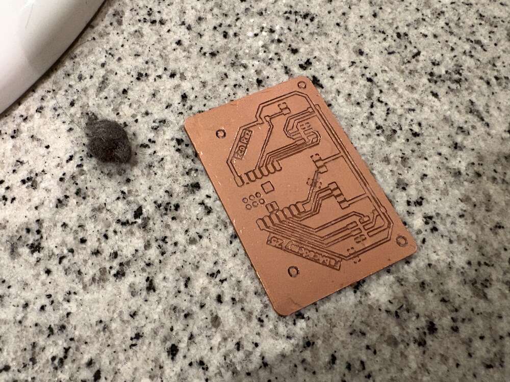
This week I design and produce the PCB for my final project, followed by 6 pcb for the load cell.
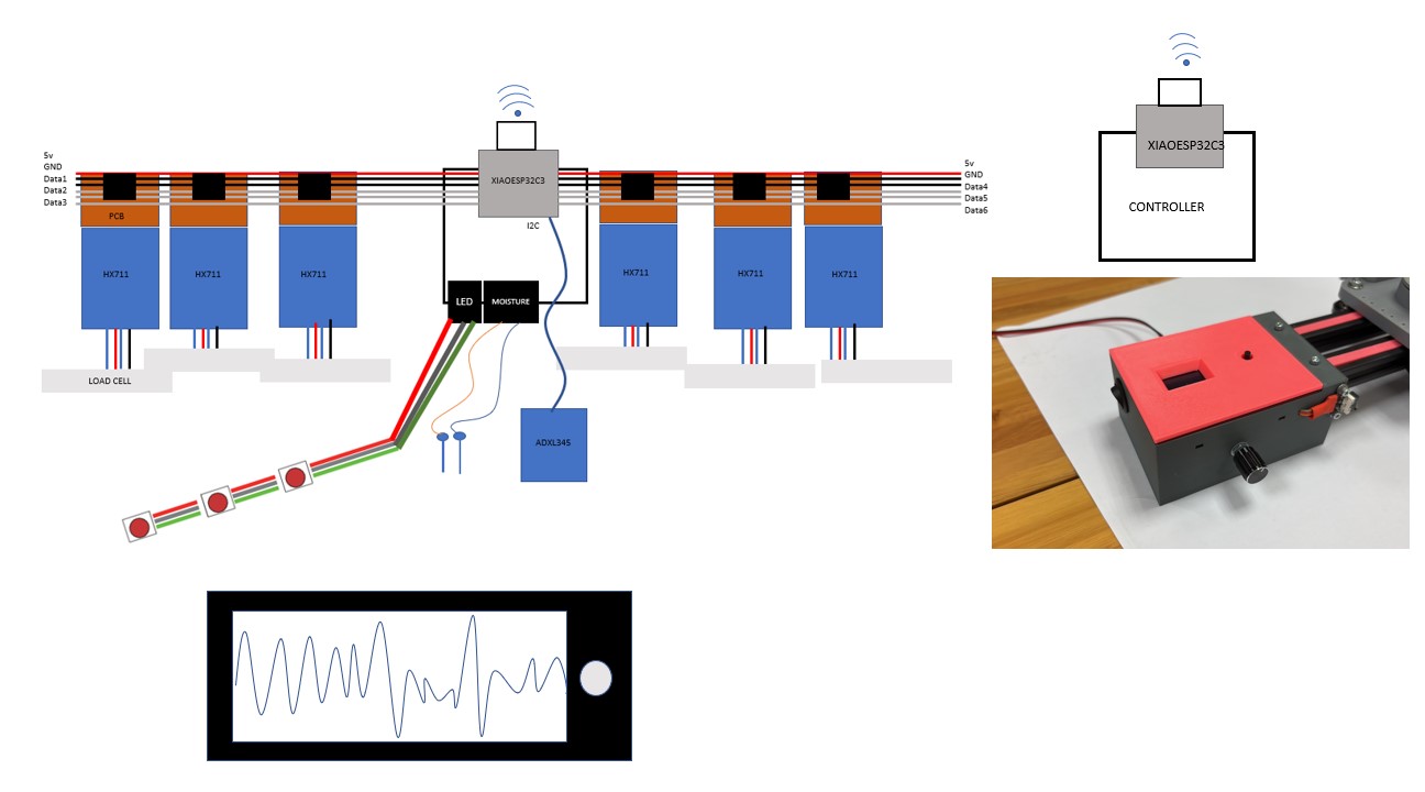
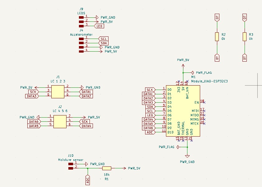
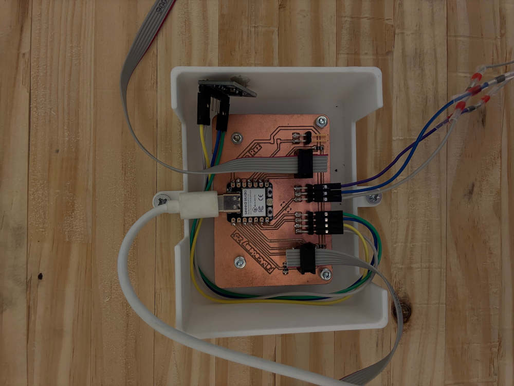
In this image it can be seen the principal PCB with 2 ribon conectors led lights and a accelerometer conector
This PCB serves as the central hub for data acquisition and communication within the system. It collects real-time data from multiple sensors, ensuring accurate monitoring of environmental and operational conditions. The gathered data is then transmitted by wires to the led lights.
I used the Roland machine it is documented on the electronics production page for the pcb
I used a printed support to stabilize the pcb, and it resulted super good
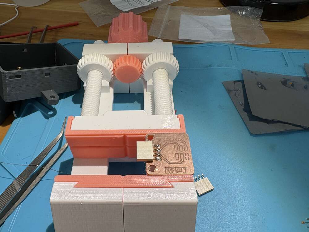
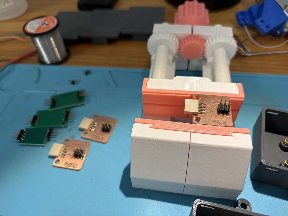
As I said before there is one principal pcb accompanied with 4 pcb for the HX711
This PCB acts as a bridge between the HX711 and the rest of the system. It ensures a secure and stable connection for the load cells, helping maintain data accuracy. Each load cell will have its own dedicated PCB, making the system more organized, easier to manage, and reducing the risk of interference.
On both side of the bridge there was 1 LC1-4 with the following design:


And a LC2-5 with the following design:


Always clean the pcb because sometimes the same copper can provoke short circuit
BOM
| Material | Amount | Cost per unit € | Total € |
|---|---|---|---|
| Spanish Pinus sylvestris wooden boards of 240x40x28 mm link | 3 | 35.99 | 107.97 |
| threaded steel rod M4link | 6 | 1.09 | 6.54 |
| Single-sided white laminated plywood link | 2 | 31.85 | 63.7 |
| MDF board link | 1 | 11.99 | 11.99 |
| Load Cells link | 6 | 1.5 | 9 |
| acceleromter link | 1 | 3 | 3 |
| Led lights White PCB, 5m 30 IP30 WS2812B link | 1 | 3.38 | 3.38 |
| copper board link | 2 | 1 | 2 |
| PinHeader_01x04_P2.54mm_Horizontal_SMD link | 9 | 0.59 | 5.31 |
| Ribbon cable link | 10 m | 10,30 | 10,03 |
| R_1206 0 Ohm RC1206FR-070RL link | 2 | 0.09 | 0.18 |
| XIAO-ESP32C3 link | 1 | 4.39 | 4.39 |
| PinHeader_02x03_P2.54mm_Vertical_SMD link | 6 | 0.55 | 3.3 |
| PinHeader_01x03_P2.54mm_H_SMD link | 6 | 3.04 | 18.24 |
Week 18: Mounting structure and laser cutting
This week I mount the structre and do the supports so it can have the stability itself
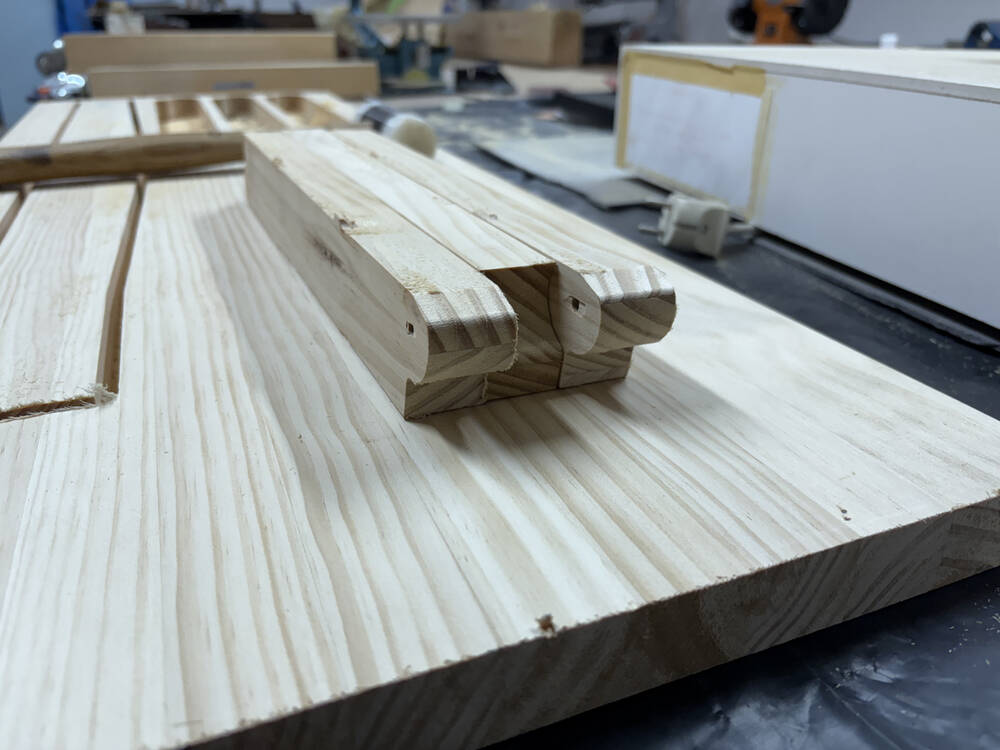
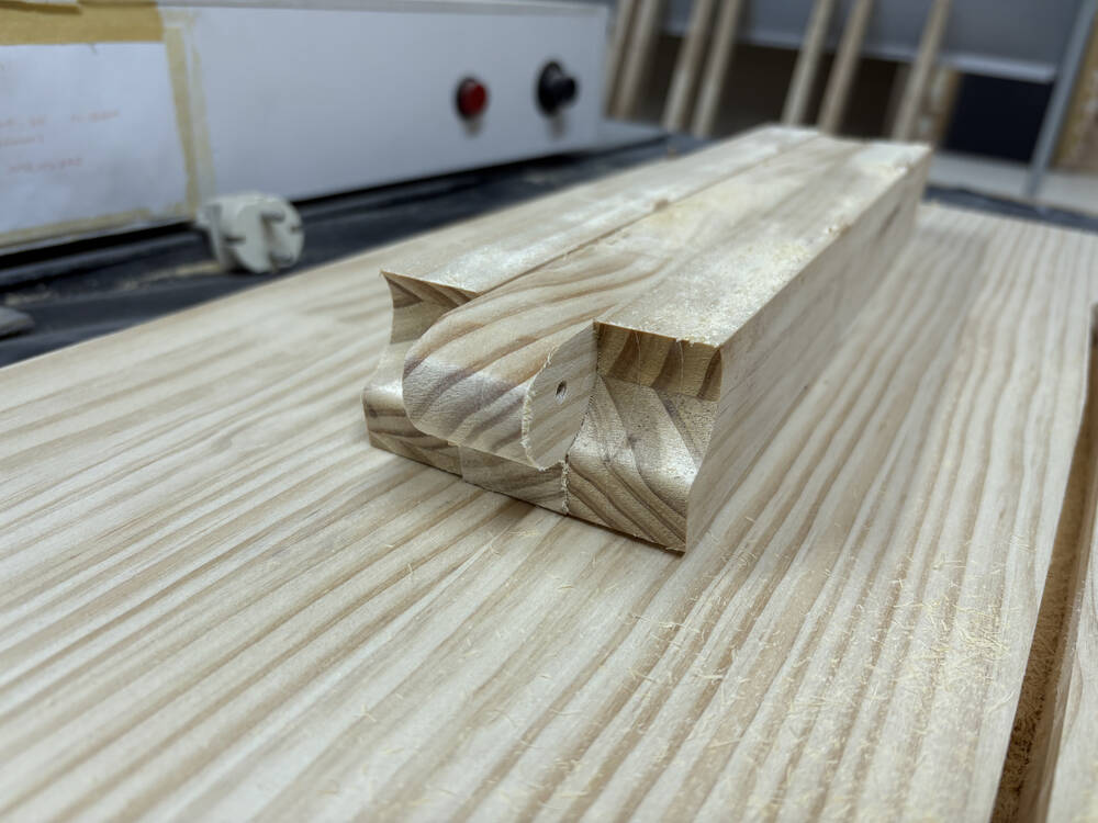
Here you can see the dowell
and the union
I also have to do the supports and traspase the loads to the ground.
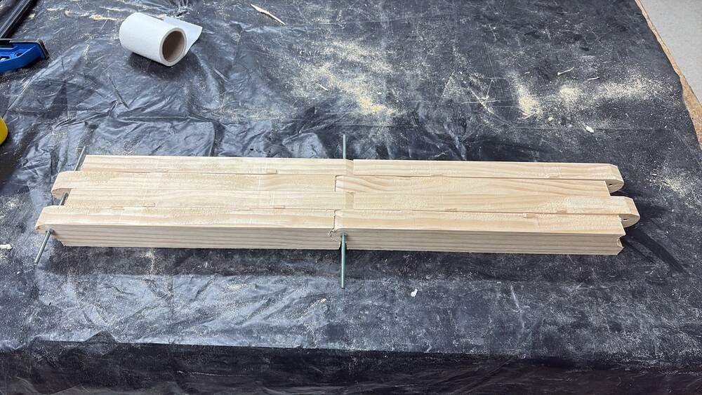
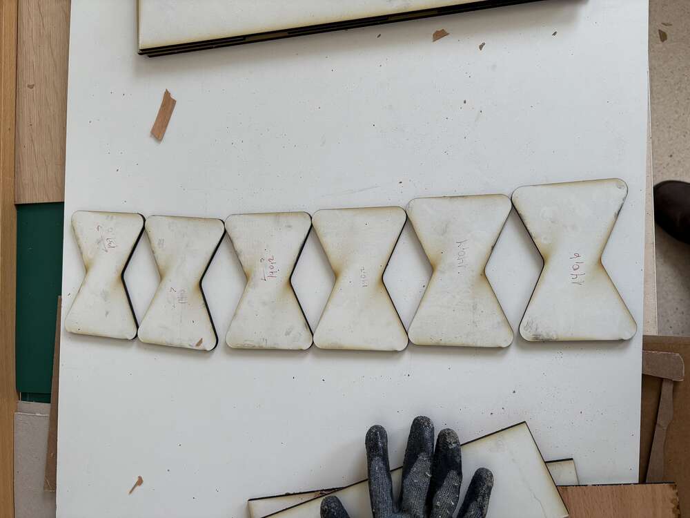
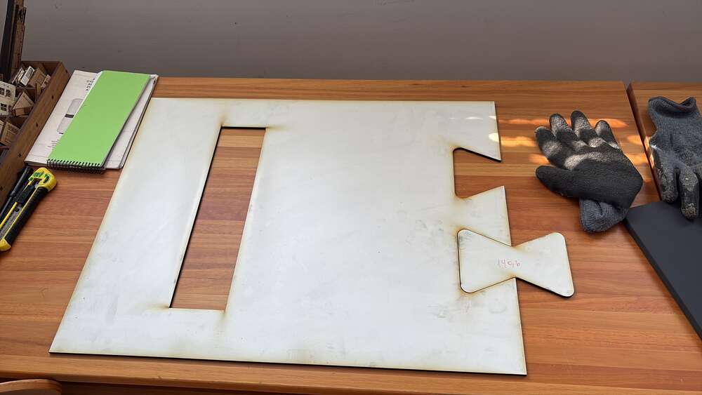
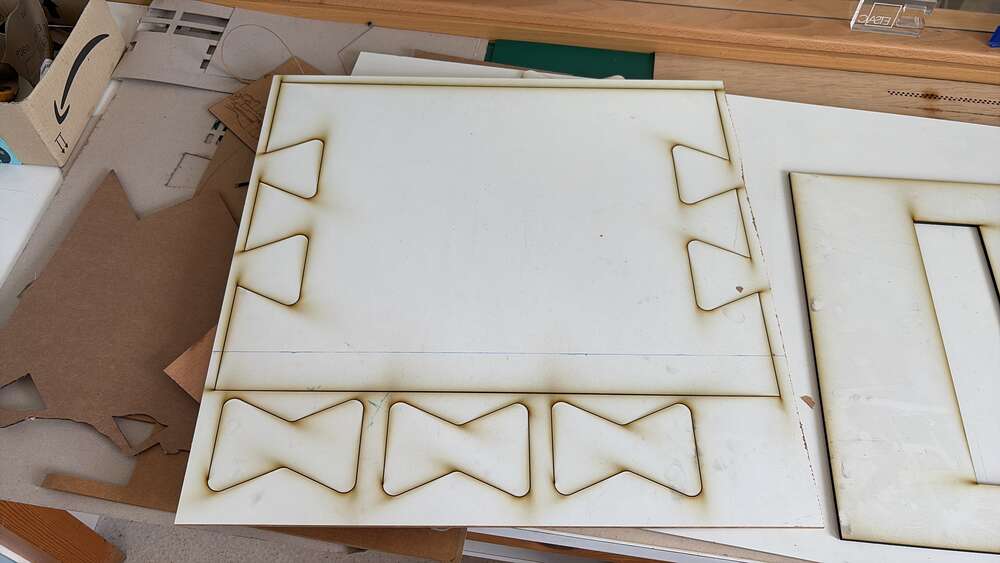
There one was on problem yet, the traction of the supports it has to be canceled, so i design a tipycal conection of 4 mm wooden boards.
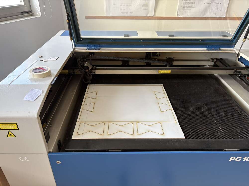
I did a lot of tests to have the correct measurement, finally yhe correct measure was 140.6 mm large.
Finally, the structure was ready to support loads and to continue working on the electronics
Week 20: System integration 3D printing
This week I did boxes to protect the electronics and that everything is on its position
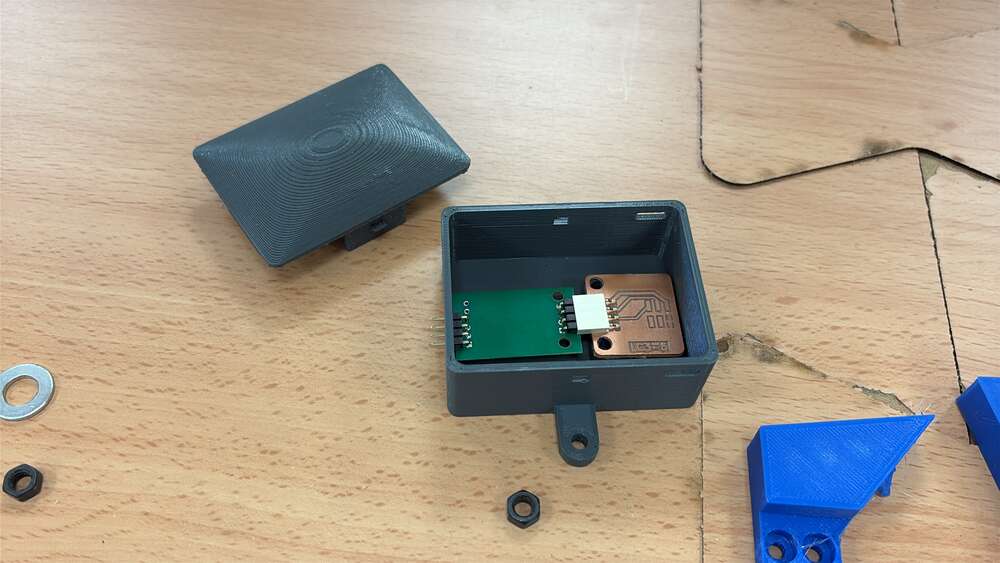
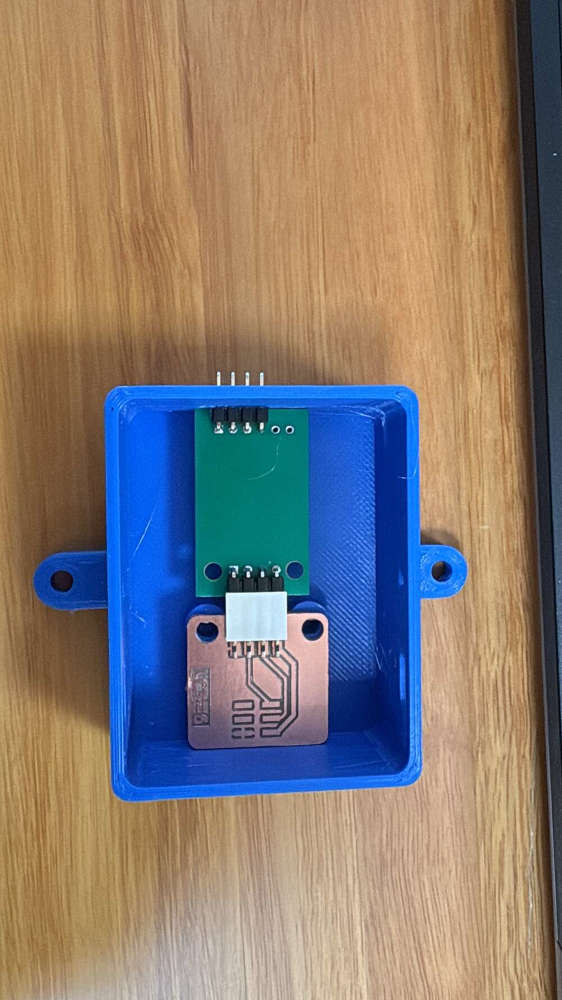
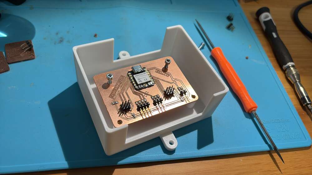
For the principal pcb I did a box with large holes so i dont have problems with wiring
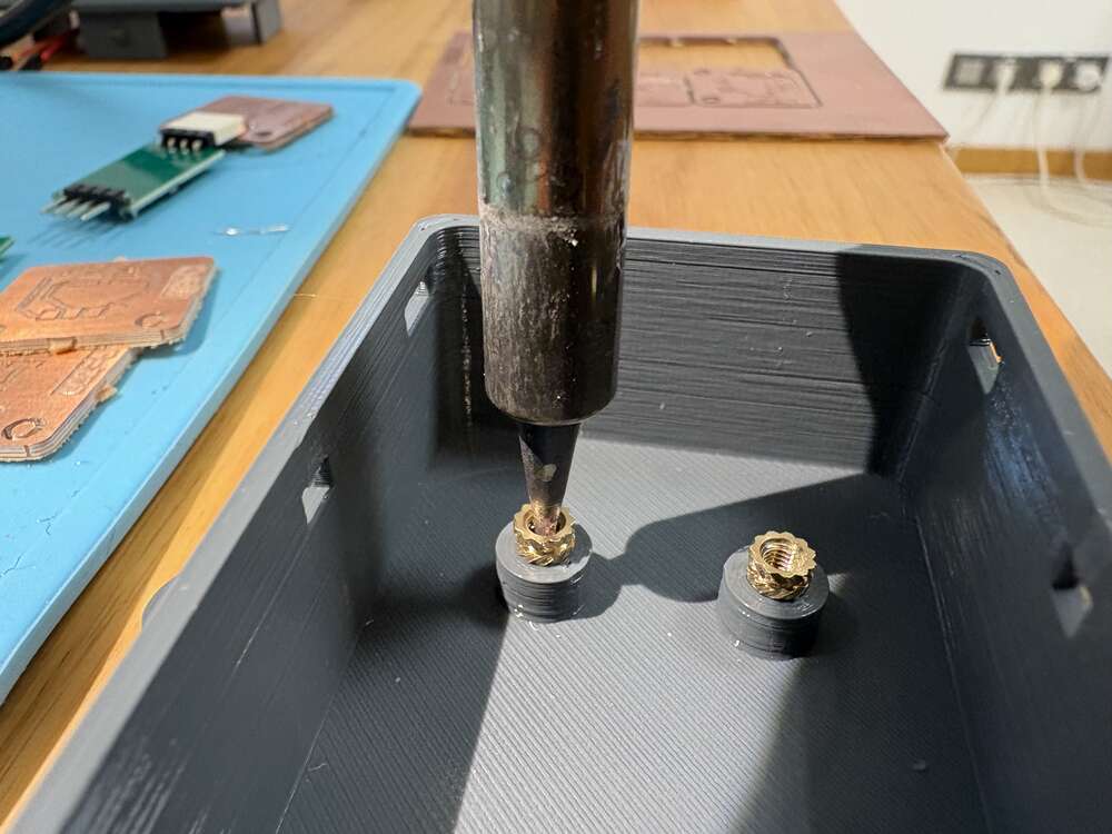
I used threaded inserts to add strong screw threads to my 3D printed part
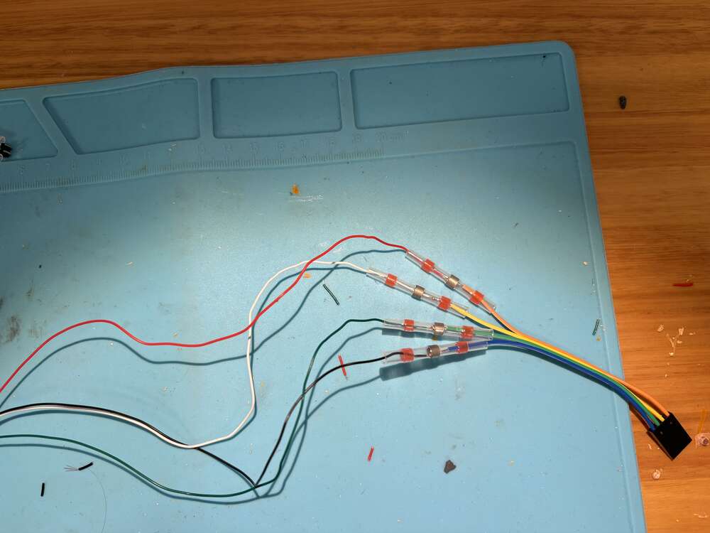
I used from ctronics a very nice connector that gives rigidity to the connection and it is very easy to solder.
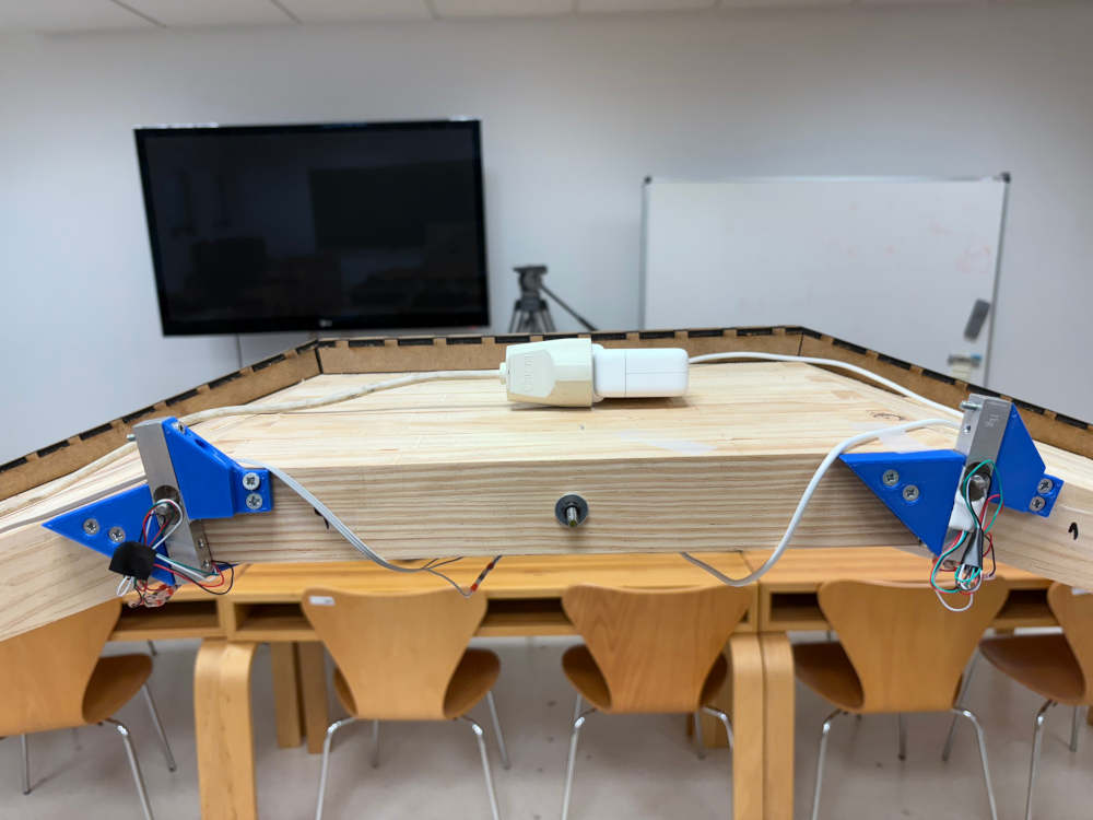
Once it was ready I assembled with the structure.
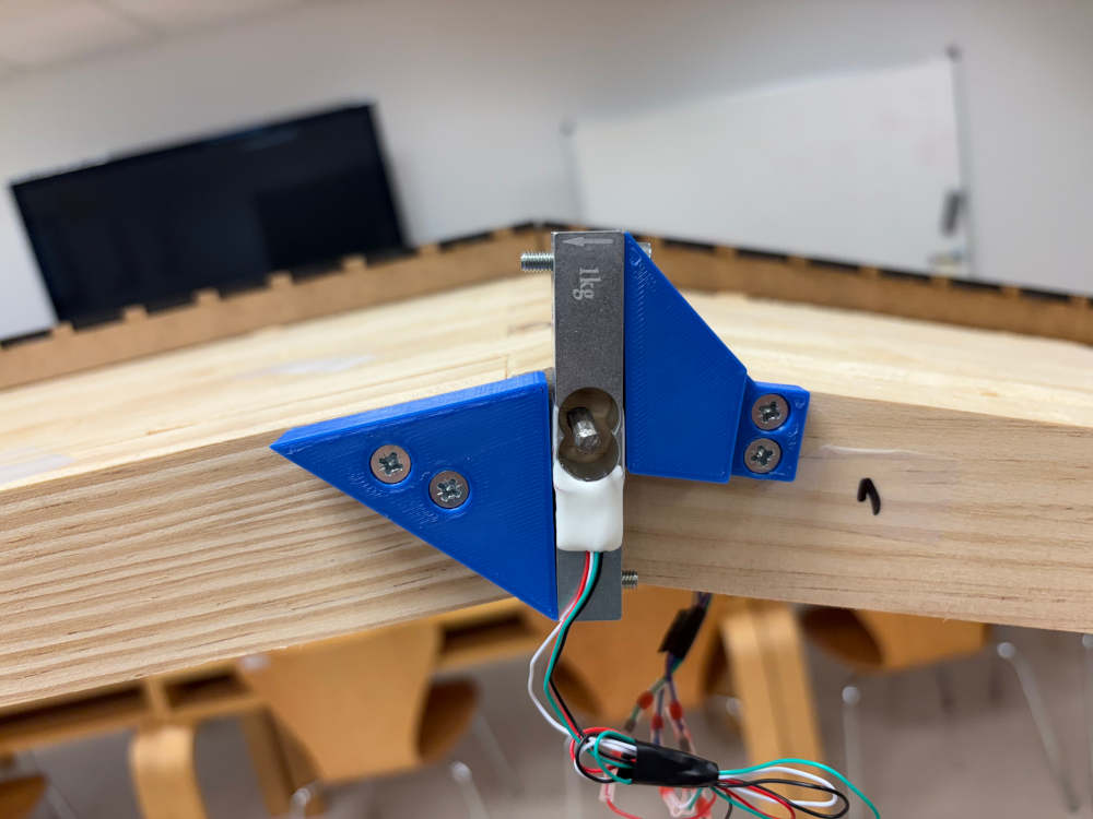
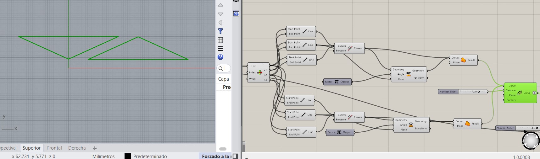
Lastly, for the first support I did bascially a triangle and then fixed to the wodden part and the load cells.
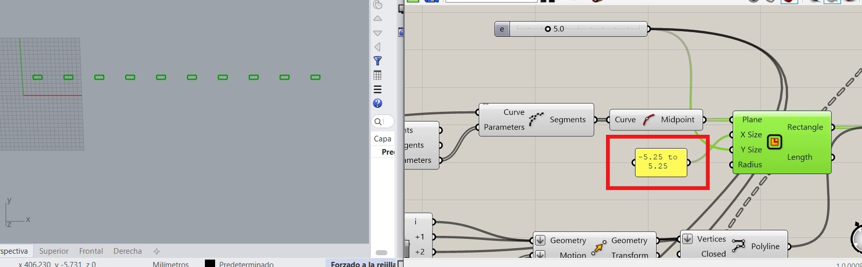
The second part is simpler because it is just a triangle, where I used the code of V3 and the middle point of the joints to do the rectangle that I used as reference.
Finally these is how the parts are installed.
First test
On monday I tried some first test before I start finishing the project
For the led lights with I combine wood worked on the laser machine and 3d print
- Laser cutting
The box for the led light was done with the laser cutting machine, the design was primordial so this can work properly. The length was the same that the wodden parts so it fits with the arch curvature.
With this parameter I controlled the tolerance of the parts so they doesn’t move. However, I fixed them with glue
Finally, these are the 3 parts I cutt on the table 7 times
- Print The ideas of the led was that the strip is pressured by the 3d print so it does not move. First I did a square and trace a diagonal. then did a scale
Finally I put fillets on the corners. It looks cool.
and these are the parts I printed on the 3d printing machine
Inside the box
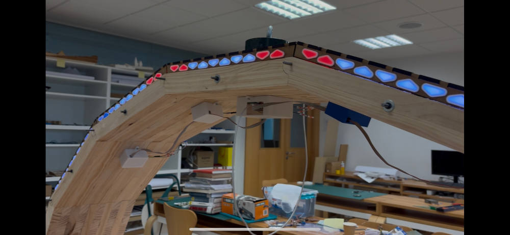
When it is already installed this is how it looks:
hx711 on the middle
hx711 most far of the central hub
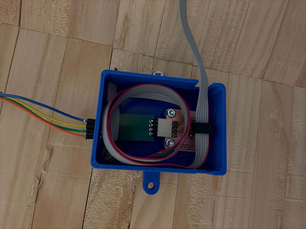
central hub:
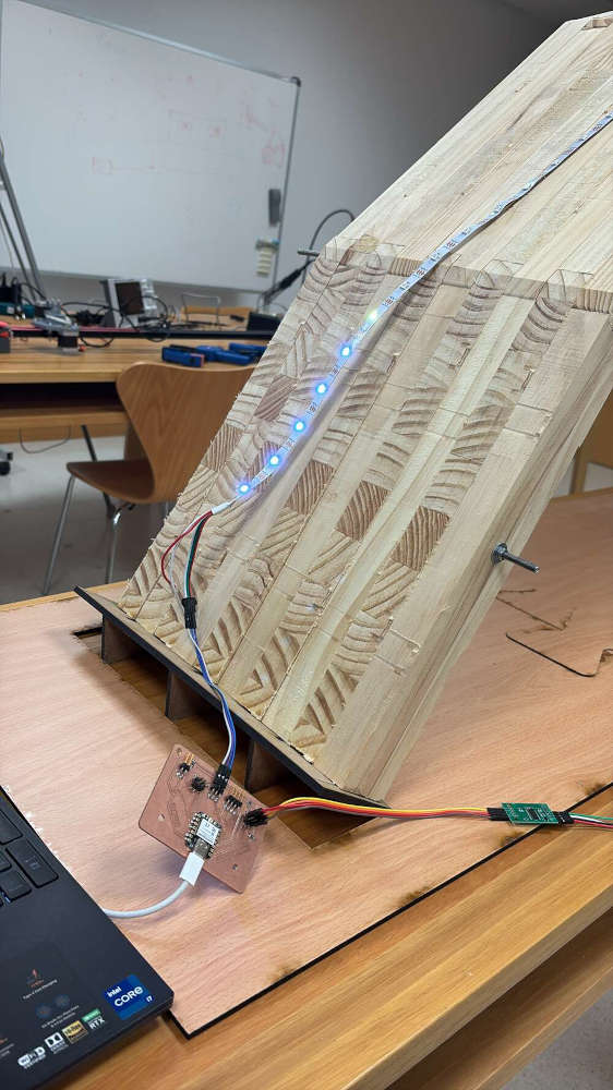
which is placed just in the middle of the arch above the woodden table that is on the highest point. like on the following image. Also in the image we can see the supply of the power to the central-hub is made with normal current
On the other hand, for the box the LED light to fit with the arch curvature I used the parametric design and the information it gave me
Finally this week I could not work on the fablab because it was closed during the weekend so I took things home and work on embedded programming.
This was the result:
- Accelerometer
- Load Cell
During the afternoon I did last tests and it was all ok to proceed with the video and slide at night and during tuesday morning.
First a calibration for the system is needed, the code is for a 5kg load on the middle.
Once it is ready if I applied a load on an extreme of the arch that load cell is having traction, while the other ones are having the bending moment on the other direction.
If I applied the load in the middle is it symetrically distribuited the load, a very efficient system.
Also if I move the arch the accelerometer gives me how the arch is moving depending on the colour and the intensity of the led lights
finally, here you can see from closer the arch and the system working.
Coding
The coding took me the last couples of weeks of the project, here I will explain in this section the most relevant aspects of the code I have developed to link the load cell readings with the representation of the forces on the led lights.
I divide the code on the following sections:
1. Library imports Wire: I2C communication (used by the ADXL345 accelerometer). Adafruit_Sensor + Adafruit_ADXL345_U: Support for the ADXL345 accelerometer. Adafruit_NeoPixel: Controls the LED ring or strip. HX711_MP: Custom library to handle multiple HX711 load cells.
#include <Wire.h>
#include <Adafruit_Sensor.h>
#include <Adafruit_ADXL345_U.h>
#include <Adafruit_NeoPixel.h>
#include "HX711_MP.h"
2. Led and load cell pins
#define PIN        D6
#define NUMPIXELS  78
#define DATA_PIN_1 D2
#define DATA_PIN_2 D3
#define DATA_PIN_3 D9
#define DATA_PIN_4 D8
#define CLOCK_PIN  D0
3. LEDs Assigned to Each Load Cell
Each array contains the LED indices corresponding to each scale.
const int scale1_leds[] = {19,20,21,22,23};
...
const int scale4_leds[] = {52,53,54,55,56};
4. Object Instances and Variables
Instances for the NeoPixel strip, the ADXL345 sensor, and 4 load cells. Calibration data: offsets (tare) and scaling factors for each load cell. Controls intensity of LEDs. White = half brightness. Vibration thresholds for each axis from the accelerometer.
Adafruit_NeoPixel pixels(NUMPIXELS, PIN, NEO_GRB + NEO_KHZ800);
Adafruit_ADXL345_Unified accel = Adafruit_ADXL345_Unified(12345);
HX711_MP scale1(2), scale2(2), scale3(2), scale4(2);

float offset1 = 0, factor1 = 1.0;
...
float offset4 = 0, factor4 = 1.0;

unsigned long lastResetTime = 0;

const int MAX_INTENSITY = 100;
const int WHITE = MAX_INTENSITY / 2;

const float THRESH_X = 1.05, MAX_X = 1.1;
const float THRESH_Y = 0.1, MAX_Y = 0.2;
const float THRESH_Z = 0.1, MAX_Z = 0.2;
5. SETUP
Initializes serial communication, NeoPixels, ADXL345 accelerometer, and HX711 load cells. Sets accelerometer range to ±16g. Sets all HX711s to “average mode”. Runs a startup light animation. Calibrates load cells automatically. Sets all LEDs to white to indicate ready status.
void setup() {
  Serial.begin(115200);
  pixels.begin();
  accel.begin();
  accel.setRange(ADXL345_RANGE_16_G);

  scale1.begin(DATA_PIN_1, CLOCK_PIN);
  scale2.begin(DATA_PIN_2, CLOCK_PIN);
  scale3.begin(DATA_PIN_3, CLOCK_PIN);
  scale4.begin(DATA_PIN_4, CLOCK_PIN);

  scale1.set_average_mode();
  scale2.set_average_mode();
  scale3.set_average_mode();
  scale4.set_average_mode();


  startupLightRun();


  calibrateScalesAuto();


  setAllWhite();
  pixels.show();

}
6. MAIN LOOP
Reads acceleration in X, Y, Z axes, normalized by dividing by gravity (9.81).
  sensors_event_t e;
  accel.getEvent(&e);

  float x = abs(e.acceleration.x / 9.81);
  float y = abs(e.acceleration.y / 9.81);
  float z = abs(e.acceleration.z / 9.81);

  unsigned long now = millis();
Gets raw data from HX711, subtracts offset, scales it, then converts from grams to kilograms.
  float w1 = (scale1.get_value(5) - offset1) / factor1 / 5000.0;
  float w2 = (scale2.get_value(5) - offset2) / factor2 / 5000.0;
  float w3 = (scale3.get_value(5) - offset3) / factor3 / 5000.0;
  float w4 = (scale4.get_value(5) - offset4) / factor4 / 5000.0;
Logs the weights to the Serial Monitor for debugging.
  if (Serial) {
    Serial.print("Pesos (kg): ");
    Serial.print("W1: "); Serial.print(w1, 3); Serial.print("\t");
    Serial.print("W2: "); Serial.print(w2, 3); Serial.print("\t");
    Serial.print("W3: "); Serial.print(w3, 3); Serial.print("\t");
    Serial.print("W4: "); Serial.println(w4, 3);
  }
Each group of LEDs changes color: Red: Weight detected (> 0.05 kg) Blue: Negative weight (< -0.05 kg, likely tension or error) Off: Near-zero weight
  updateScaleLEDs(scale1_leds, 5, w1);
  updateScaleLEDs(scale2_leds, 5, w2);
  updateScaleLEDs(scale3_leds, 5, w3);
  updateScaleLEDs(scale4_leds, 5, w4);
Detect Vibration from Accelerometer: Detects the dominant axis with significant movement: X → red Y → green Z → blue If detected: Blinks the acceleration-specific LEDs every 250 ms Keeps fixed LEDs (corners) purple If no vibration is detected, the affected LEDs are white (neutral status). Every 30 seconds, resets the load cells: Runs the startup animation Updates the offset to the current raw value (new “zero”)
  if (x > THRESH_X && x >= y && x >= z) {
    val = x; color = pixels.Color(MAX_INTENSITY, 0, 0);  // Rojo
  } else if (y > THRESH_Y && y >= x && y >= z) {
    val = y; color = pixels.Color(0, MAX_INTENSITY, 0);  // Verde
  } else if (z > THRESH_Z && z >= x && z >= y) {
    val = z; color = pixels.Color(0, 0, MAX_INTENSITY);  // Azul
  }

  if (color != 0) {

    if (now - lastBlink > 250) {
      lastBlink = now;
      blinkState = !blinkState;
      updateAccelLEDs(blinkState ? color : 0);
      setFixedPurpleLEDs();
      pixels.show();
    }
  } else {

    updateAccelLEDs(pixels.Color(WHITE, WHITE, WHITE));
    setFixedPurpleLEDs();
    pixels.show();
  }


  if (now - lastResetTime > 30000) { // 10 segundos
  lastResetTime = now;


  startupLightRun();


  offset1 = scale1.get_value(5);
  offset2 = scale2.get_value(5);
  offset3 = scale3.get_value(5);
  offset4 = scale4.get_value(5);

  Serial.println("Nuevo offset aplicado (reset de galgas).");
  }


  delay(10);
Helper Functions
startupLightRun()
Animates the LEDs from left to right and back in white.
  for (int i = 0; i < NUMPIXELS; i++) {
    pixels.setPixelColor(i, pixels.Color(MAX_INTENSITY, MAX_INTENSITY, MAX_INTENSITY));
    pixels.show();
    delay(9);
    pixels.setPixelColor(i, 0);
  }

  for (int i = NUMPIXELS - 1; i >= 0; i--) {
    pixels.setPixelColor(i, pixels.Color(MAX_INTENSITY, MAX_INTENSITY, MAX_INTENSITY));
    pixels.show();
    delay(9);
    pixels.setPixelColor(i, 0);
  }
calibrateScalesAuto()
Performs auto calibration:
Waits 3s for zero weight
Reads offsets
Waits 2s for 5kg weight to be added
Reads new values and computes scale factor
  Serial.println("Calibrando sin PC. Espera 5 segundos y coloca peso 5kg.");
  delay(3000);


  offset1 = scale1.get_value(5);
  offset2 = scale2.get_value(5);
  offset3 = scale3.get_value(5);
  offset4 = scale4.get_value(5);

  Serial.println("Pesa colocado. Calculando factores...");

  delay(2000);


  float val1 = scale1.get_value(10);
  float val2 = scale2.get_value(10);
  float val3 = scale3.get_value(10);
  float val4 = scale4.get_value(10);

  factor1 = (val1 - offset1) / (5 * 1000);
  factor2 = (val2 - offset2) / (5 * 1000);
  factor3 = (val3 - offset3) / (5 * 1000);
  factor4 = (val4 - offset4) / (5 * 1000);

  Serial.println("Calibracion completa.");
setAllWhite()
Sets all LEDs to medium-bright white.
  for (int i = 0; i < NUMPIXELS; i++) {
    pixels.setPixelColor(i, pixels.Color(WHITE, WHITE, WHITE));
  }
  pixels.show();
updateAccelLEDs(uint32_t color)
Updates a predefined set of LEDs with a given color (used for accelerometer response).
  int accel_leds[] = {
    2,3,4,5,6,7,8,9,10,11,12,13,14,15,16,17,18,
    24,25,26,27,28,29,
    35,36,37,38,39,40,
    46,47,48,49,50,51,
    57,58,59,60,61,62,63,64,65,66,67,68,69,70,71,72
  };
  int count = sizeof(accel_leds) / sizeof(accel_leds[0]);
  for (int i = 0; i < count; i++) {
    pixels.setPixelColor(accel_leds[i], color);
  }
setFixedPurpleLEDs()
Always keeps the first 4 and last 6 LEDs purple for orientation.
  uint32_t purple = pixels.Color(MAX_INTENSITY, 0, MAX_INTENSITY); // R+B = morado
  pixels.setPixelColor(0, purple);
  pixels.setPixelColor(1, purple);
  pixels.setPixelColor(2, purple);
  pixels.setPixelColor(3, purple);
  for (int i = 72; i <= 77; i++) {
    pixels.setPixelColor(i, purple);
  }
updateScaleLEDs(const int* ledIndices, int count, float weight)
Changes a set of LEDs based on weight:
Red if weight > +0.05 kg (compression)
Blue if weight < -0.05 kg (tension or error)
Off if near zero
  uint8_t r = 0, g = 0, b = 0;

  if (weight > 0.05) {
    int intensity = (int)(MAX_INTENSITY * min(weight / 5.0, 1.0));
    r = intensity;
  } else if (weight < -0.05) {
    int intensity = (int)(MAX_INTENSITY * min(abs(weight) / 5.0, 1.0));
    b = intensity;
  }
  for (int i = 0; i < count; i++) {
    pixels.setPixelColor(ledIndices[i], pixels.Color(r, g, b));
  }
Files
Arch Grasshopper arch_v3.gh
Dovetail Grasshopper roseton.gh
Bridge support Grasshopper SOPORTE_PUENTE.gh
Led 3d printed part Grasshopper tapas_leds.ghPrincipal box system integration STL caja_grande.stl
HX711 box system integration STL caja_HX711_3.stl
fixing part for load cell 1 STL pieza_fijacion.stl
fixing part for load cell 2 STL pieza_fijacion2.stl
led cover STL tapa_led.zipend parts of the bridge 3dm piezas_apoyo.3dm
end parts of the bridge dxf piezas_apoyo.dxf
support for drilling machine dxf soporte_drill.dxfwodden parts for cnc Vcarve piezas_cnc.zip
wodden parts 2 for cnc Vcarve piezas_cnc_40.zip
end parts of the bridge Vcarve soporte.zip
Bridge supports Vcarve Soporte_puente.zipfinal code of the final project Arduino IDE final_codev3.zip
Principal pcb Kicad pcb_ACC.zip
HX711 pcb Kicad PCB_basculas.zip