week 9 Input Devices
Group assignment:
- Probe an input device(s)’s analog levels and digital signals
- Document your work on the group work page and reflect on your individual page what you learned
Individual assignment:
- Measure something: add a sensor to a microcontroller board that you have designed and read it.
Summary:
In this assignment, I worked on both group and individual tasks. In the group task, I tested digital signals using an oscilloscope and documented my findings. For the individual task, I integrated a button, an ADXL345 accelerometer, and a DHT11 temperature and humidity sensor with a custom PCB I designed in a previous week. I successfully programmed the button to control an LED delay, tested the accelerometer using an Adafruit example, and resolved connection issues with the DHT11 sensor by experimenting with pin configurations. I documented each step, highlighting my improved soldering skills and troubleshooting process.
Group Assignment
While my part consisted in testing digital signals with the oscilloscope. I did the HTP11 sensor which y describe in the individual assignment.

On the other hand, Pepe tested some load cells he is going to use in his project.
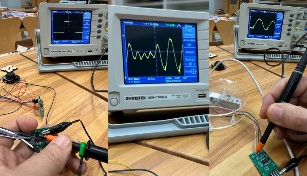
All the information and details can be seen in the group page
Individual assignment
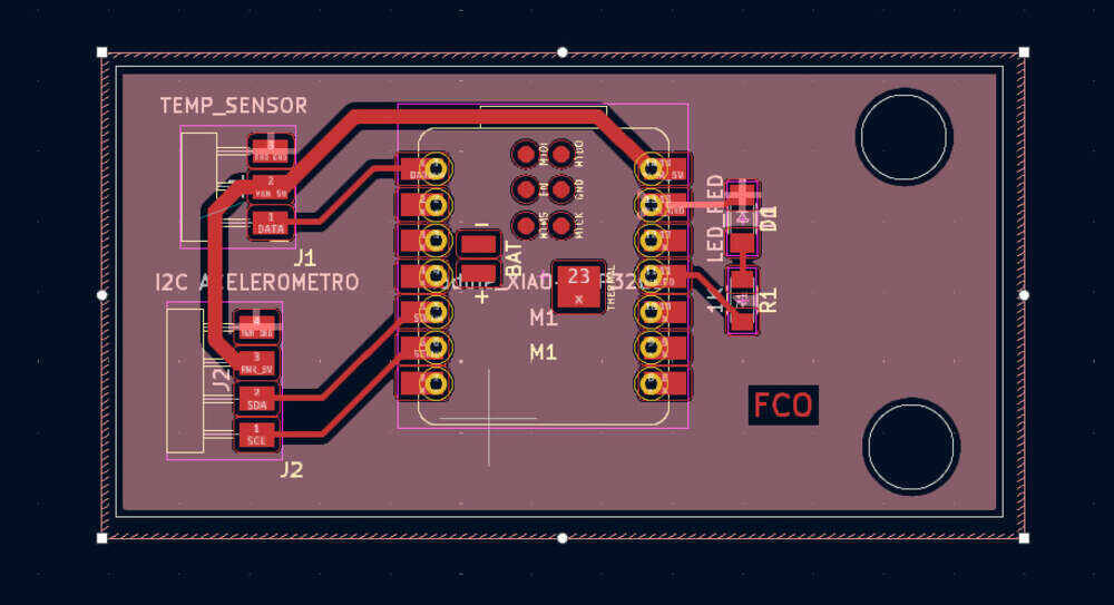
First, from the week 6 “electronical design” I did a PCB that works for this week, the idea is to connect and accelerometer, a button and a temperature and humidity sensor, already thinking of what is going to consist my final project. The PCB is on the following image, but details can be seen at week 8 page.
Button
The component is the SW262CT B3SN-211P
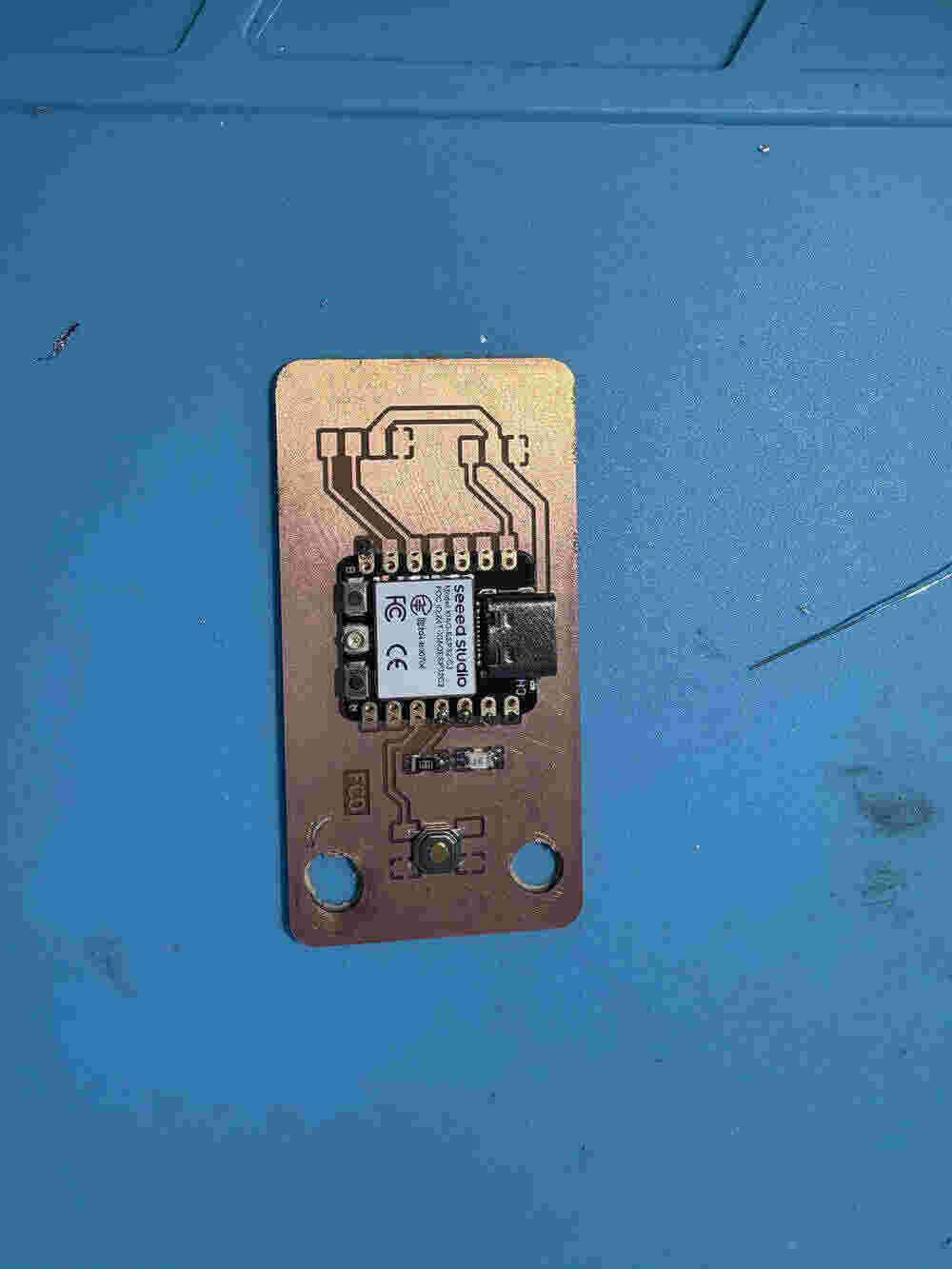
I solder the four pins of the button. I think that thanks to the previous week my soldering skills have enhanced a lot. You can see the result here:
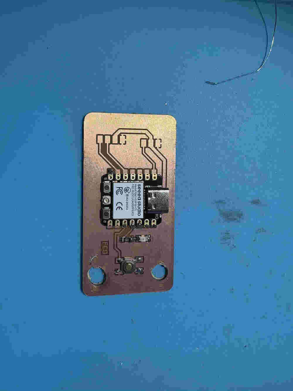
Once already solder the button it was time to program it, I did an example my peer Pepe Vazquez gave me and worked on arduino IDE. The program is the followinf but you can download it at the end of the page.
const int buttonPin = 8;     // pushbutton connected to digital pin 9
const int ledPin =  10;      // LED connected to digital pin 10

int buttonState = 0;         // variable for reading the pushbutton status

int ledDelay = 1000;         // variable for delay


void setup() {
  //
  Serial.begin(9600);
  // initialize the LED pin as an output:
  pinMode(ledPin, OUTPUT);
  // initialize the pushbutton pin as an input:
  pinMode(buttonPin, INPUT);
}

void loop() {

  // read the state of the pushbutton value:
  buttonState = digitalRead(buttonPin);

  // check if the pushbutton is pressed. If it is, the buttonState is HIGH:

  if (buttonState == HIGH) {
    ledDelay = 100; // if button is pressed fast delay
    Serial.println("boton pulsado");
  } else {
    ledDelay = 1000; // if button isn´t pressed delay 1 second
    Serial.println("boton no pulsado");
  }

   digitalWrite(ledPin, HIGH); // turn the LED on by making the voltage HIGH
   delay(ledDelay);                      // wait for 'ledDelay'
   digitalWrite(ledPin, LOW);   // turn the LED off by making the voltage LOW
   delay(ledDelay);


}
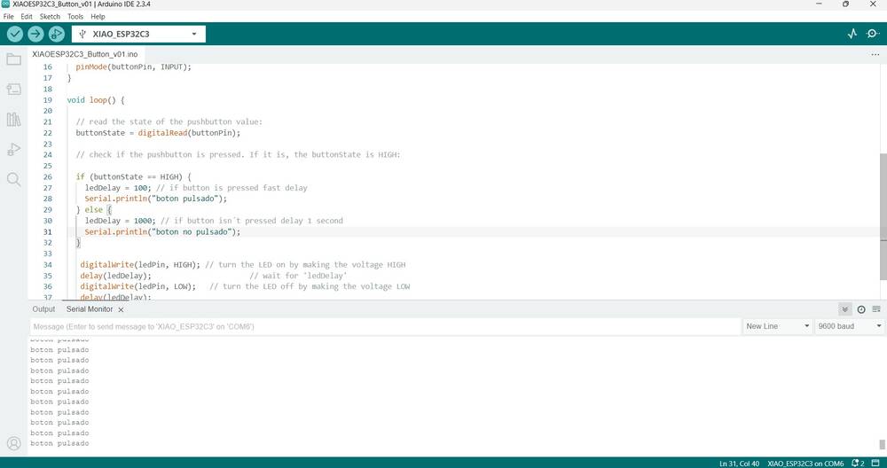
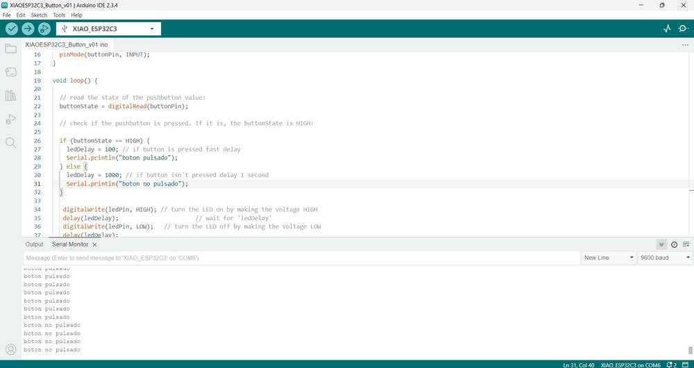
This code make the led of the pcb blink with a certain period, the when I press the button the period increses it time by 10 tenth of a second. Also, in the Serial Monitor of arduino it gave if the button is pressed or not.
Accelerometer
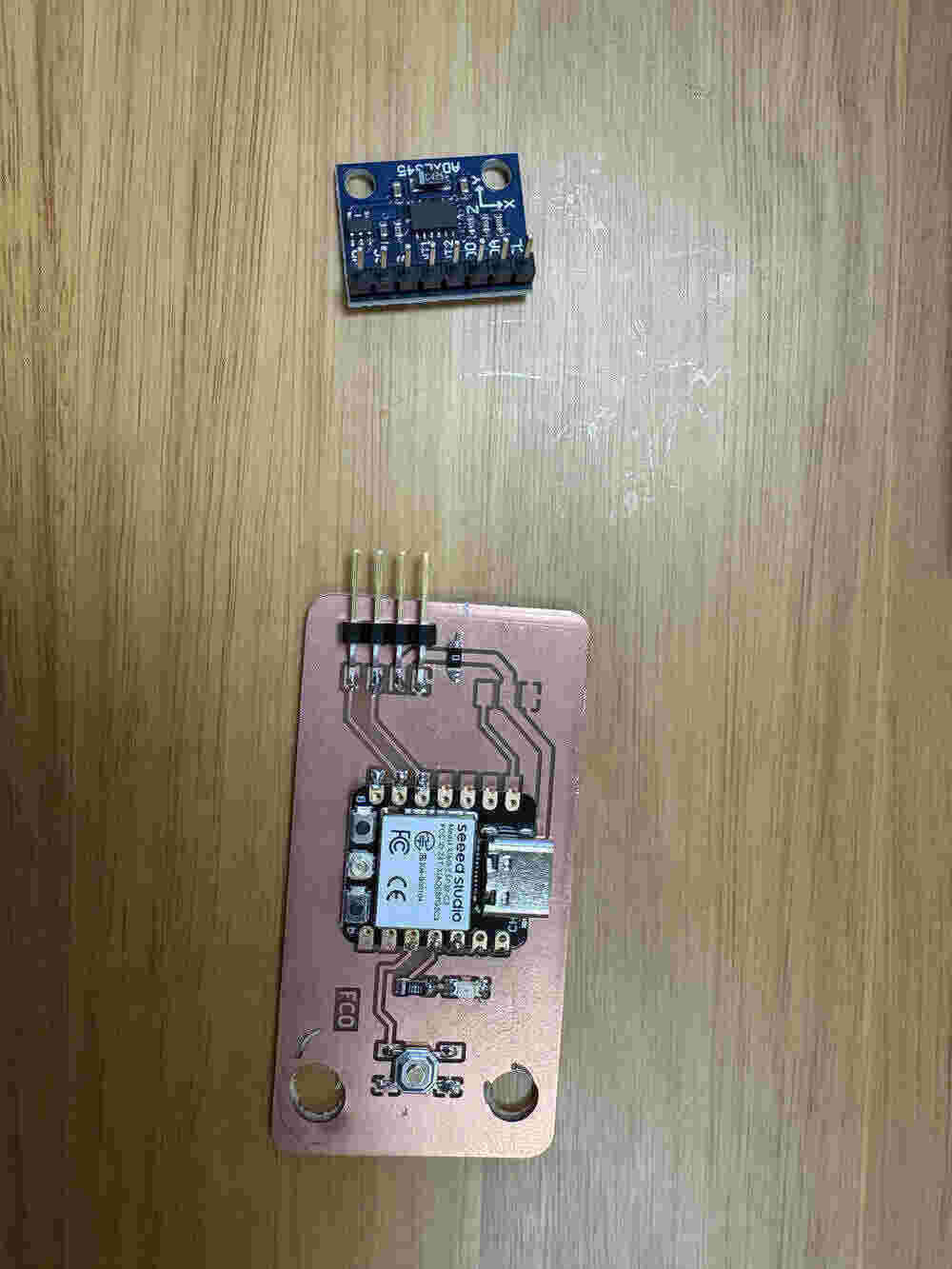
The accelerometer used was the ADXL345. First the mission was soldering the different components, so here is a image of the result.
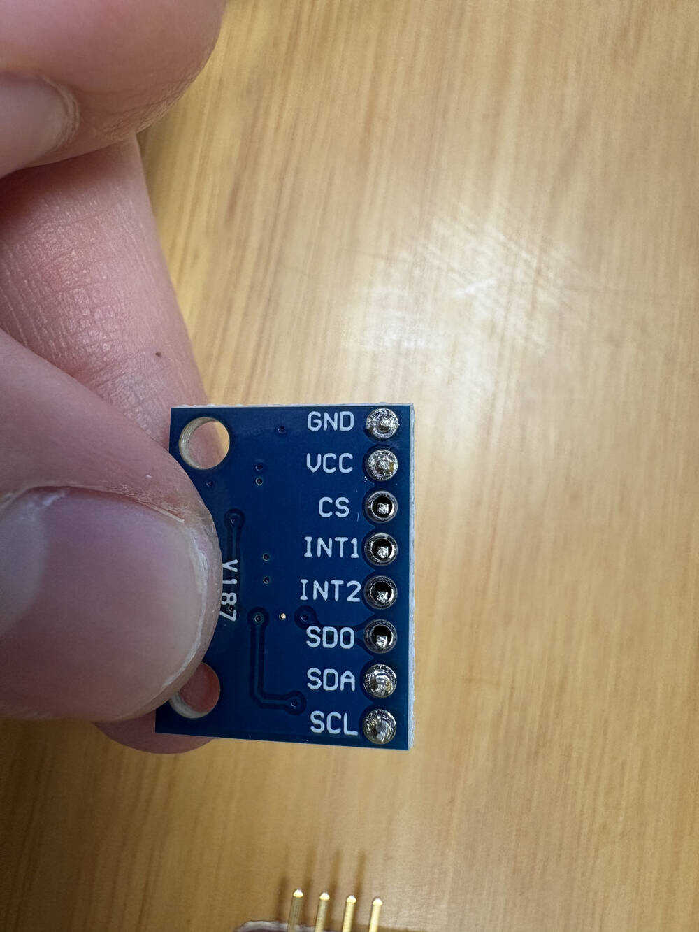
Then I had to connect the pins with cables for the communication of both components, The accelerometer use a I2C connection:
An I2C (Inter-Integrated Circuit) connection is a communication protocol commonly used in electronics to enable multiple devices to communicate with each other using only two wires: SCL (Serial Clock Line) -> Carries the clock signal that synchronizes data transfer. SDA (Serial Data Line) -> Transmits data between devices.
I used only the four pins soldered.
Result:
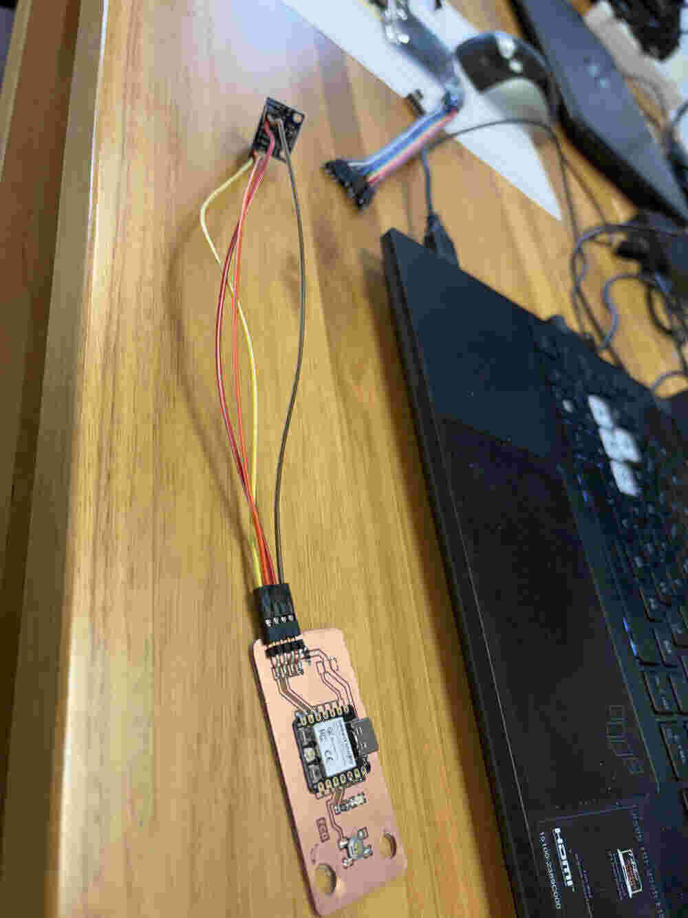
Then for the programming task I used an example given by Adafruit, is the following:
#include <Wire.h>
#include <Adafruit_Sensor.h>
#include <Adafruit_ADXL345_U.h>

Adafruit_ADXL345_Unified accel = Adafruit_ADXL345_Unified(12345);

void displaySensorDetails(void) {
    sensor_t sensor;
    accel.getSensor(&sensor);
    Serial.println("------------------------------------");
    Serial.print("Sensor:       "); Serial.println(sensor.name);
    Serial.print("Driver Ver:   "); Serial.println(sensor.version);
    Serial.print("Unique ID:    "); Serial.println(sensor.sensor_id);
    Serial.print("Max Value:    "); Serial.print(sensor.max_value); Serial.println(" m/s^2");
    Serial.print("Min Value:    "); Serial.print(sensor.min_value); Serial.println(" m/s^2");
    Serial.print("Resolution:   "); Serial.print(sensor.resolution); Serial.println(" m/s^2");
    Serial.println("------------------------------------");
    Serial.println("");
    delay(500);
}

void setup(void) {
    Wire.begin(6, 7);  // SDA = GPIO6, SCL = GPIO7
    Serial.begin(115200);
    while (!Serial);

    Serial.println("Accelerometer Test\n");

    if (!accel.begin(0x53)) {
        Serial.println("❌ No se detectó el ADXL345... Verifica las conexiones.");
        while (1);
    }

    accel.setRange(ADXL345_RANGE_16_G);
    displaySensorDetails();
}

//Sin grafico
/*
void loop(void) {
    sensors_event_t event;
    accel.getEvent(&event);

    Serial.print("X: "); Serial.print(event.acceleration.x); Serial.print("  ");
    Serial.print("Y: "); Serial.print(event.acceleration.y); Serial.print("  ");
    Serial.print("Z: "); Serial.print(event.acceleration.z); Serial.print("  ");
    Serial.println("m/s^2");

    delay(500);
}
*/

// Grafico
void loop(void) {
    sensors_event_t event;
    accel.getEvent(&event);

    Serial.print("X:"); Serial.print(event.acceleration.x); Serial.print(" ");
    Serial.print("Y:"); Serial.print(event.acceleration.y); Serial.print(" ");
    Serial.print("Z:"); Serial.println(event.acceleration.z);  // Usa println solo en el último valor

    delay(100);
}
Temparture and humidity
The pinout I took it from the page of Sara Islam.
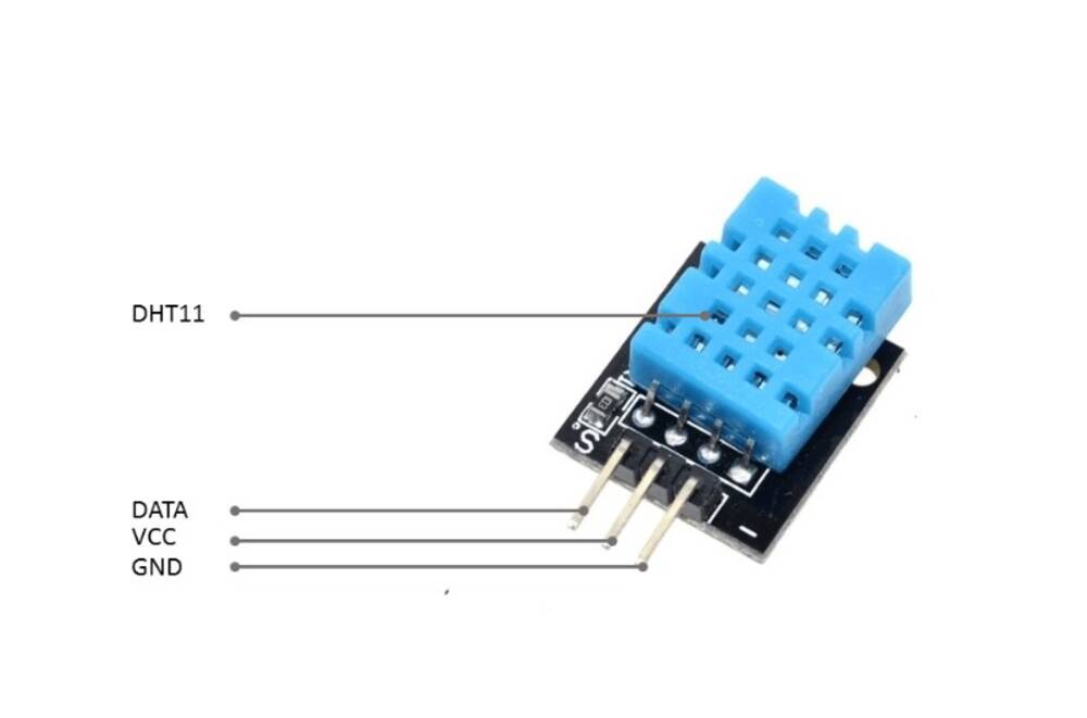
The sensor was not working and I didn’t know exactly was the reason. After of couple of hours trying to understand why I didn’t get to a solution, I saw on internet that always in the example they connect to pin 2 so I tried the arduino one to see if that was the error and connecting to pin 0 wouldn’t work.
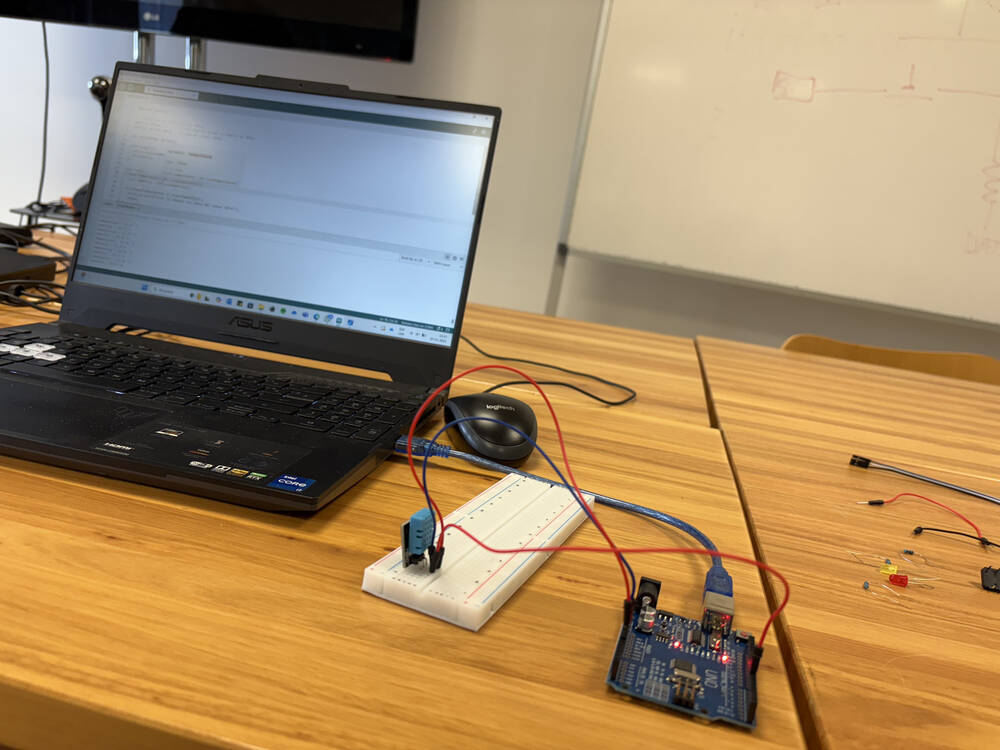
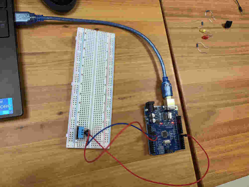
It worked well.
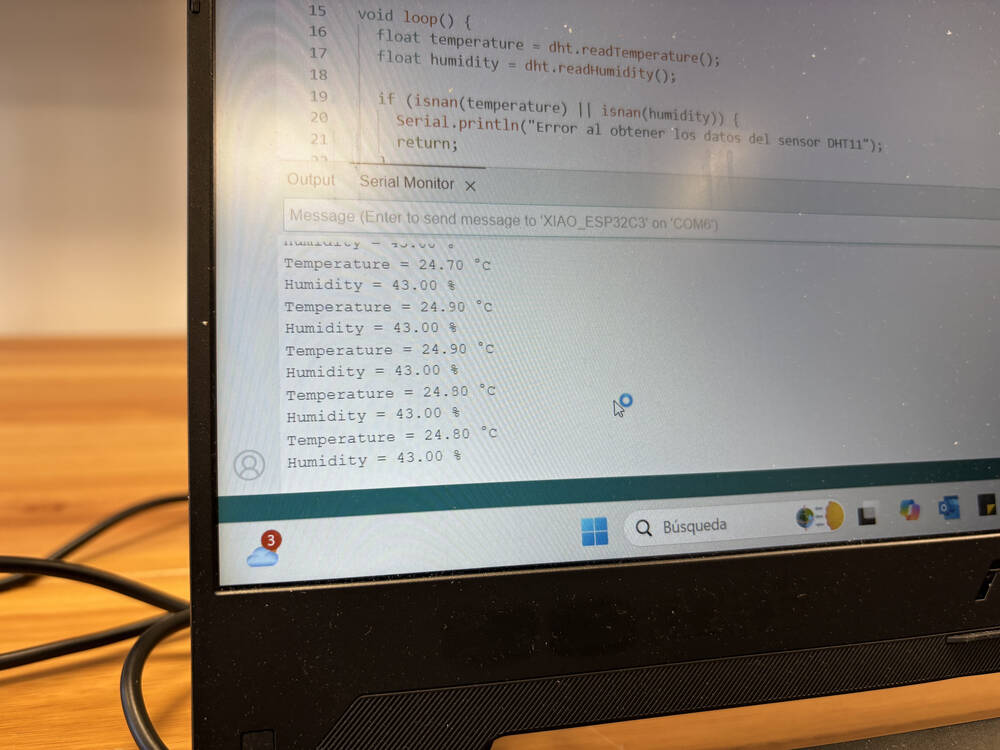
I had a first proximity to solve the problem.
To make sure that was the error I connect the sensor to the pins that at first were for the I2C connection.
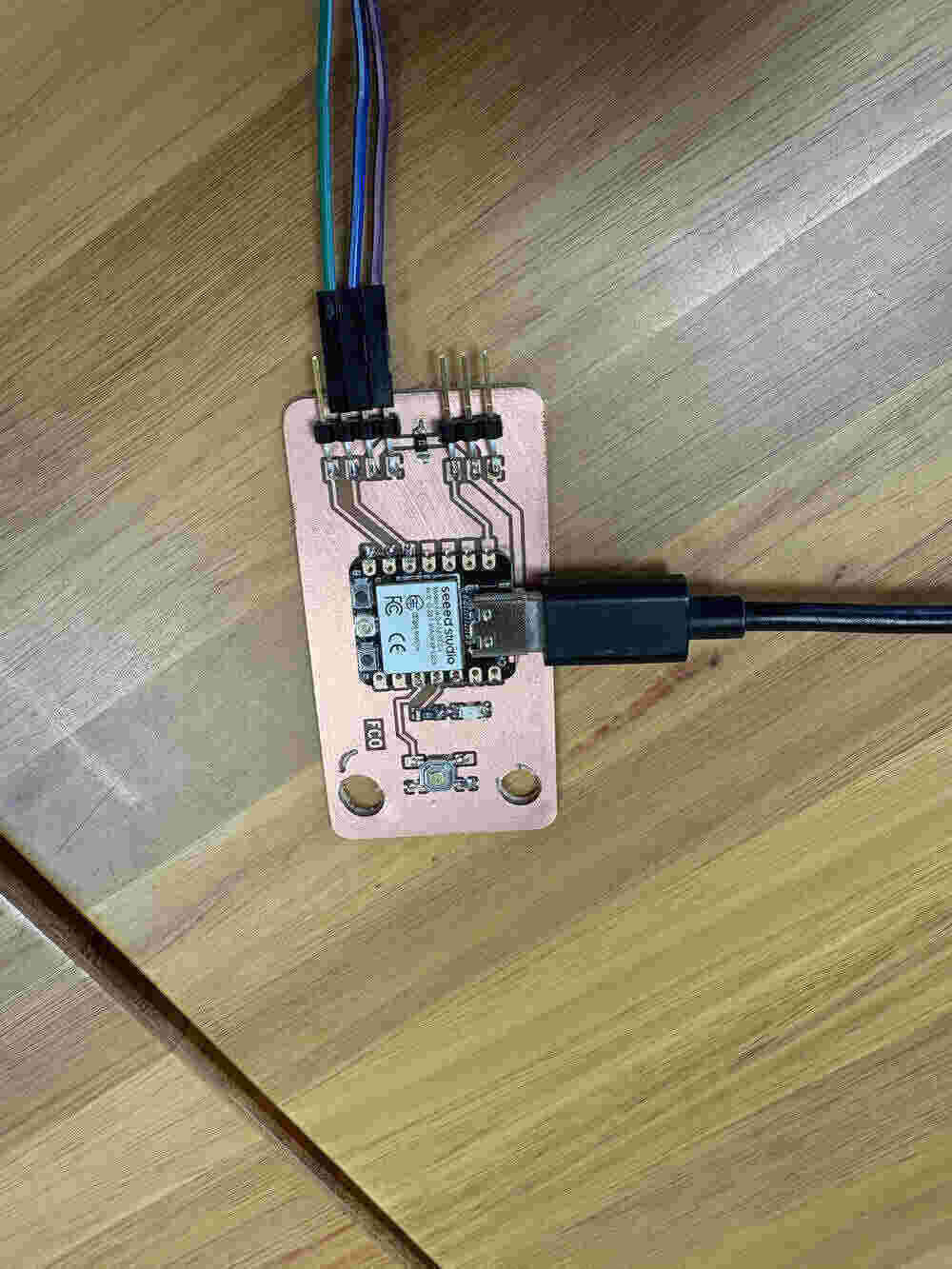
It also wroked well so I confirmed that was the error I was doing.
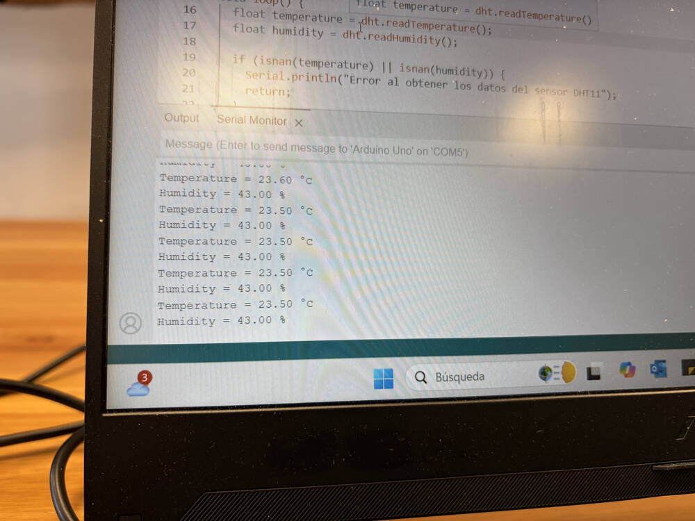
The code is the following:
#include <DHT.h>

// Definición del pin y tipo de sensor
#define DHTPIN D4       // Pin digital al que se conecta el DHT11
#define DHTTYPE DHT11    // Tipo de sensor: DHT11

DHT dht(DHTPIN, DHTTYPE);

void setup() {
  Serial.begin(115200);
  dht.begin();  // Inicialización del sensor
}

void loop() {
  float temperature = dht.readTemperature();
  float humidity = dht.readHumidity();

  if (isnan(temperature) || isnan(humidity)) {
    Serial.println("Error al obtener los datos del sensor DHT11");
    return;
  }

  Serial.print("Temperature = ");
  Serial.print(temperature);
  Serial.println(" °C");

  Serial.print("Humidity = ");
  Serial.print(humidity);
  Serial.println(" %");

  delay(5000);
}
Rading load cell with led lights
To complete the assignment finally I did a code which I use on my final project.
#include <Adafruit_NeoPixel.h>
#include "HX711_MP.h"

// ----------------- Configuración del HX711 -----------------
const uint8_t dataPin = D3;
const uint8_t clockPin = D0;
HX711_MP scale(2); // Canal A del HX711

// ----------------- Configuración NeoPixel ------------------
#define PIN        D6
#define NUMPIXELS  150
Adafruit_NeoPixel pixels(NUMPIXELS, PIN, NEO_GRB + NEO_KHZ800);

// ----------------- Configuración -----------------
void setup() {
  Serial.begin(115200);

  // Iniciar HX711
  scale.begin(dataPin, clockPin);
  scale.set_average_mode(); // Opcional: Promedia lecturas para suavizar

  // Iniciar LEDs
  pixels.begin();
  pixels.clear();
  pixels.show();
}

void loop() {
  // Leer valor bruto del sensor (sin calibración)
  float raw = scale.get_value(10); // promedio de 10 lecturas

  Serial.print("Valor crudo: ");
  Serial.println(raw);

  // Si el valor es muy bajo, consideramos que no hay peso
  if (raw < 100) {
    pixels.clear();
    pixels.show();
    return;
  }

  // Mapear el valor bruto a brillo 0–255 (ajustar el máximo a tu carga esperada)
  int brillo = map(constrain(raw, 100, 10000), 100, 10000, 0, 255);

  // Aplicar ese brillo como intensidad de color (ejemplo: azul)
  for (int i = 0; i < NUMPIXELS; i++) {
    pixels.setPixelColor(i, pixels.Color(0, 0, brillo)); // LED azul con intensidad variable
  }
  pixels.show();

  delay(100); // Pequeña pausa
}
here is the result o what the code does. If I press the arch then the light turn on and if there is more force the intensity of the light is more.
Learning Oucomes:
The learning outcomes from this assignment include enhancing soldering skills, particularly in connecting components to a PCB, and gaining experience in integrating and troubleshooting sensors like buttons, accelerometers, and temperature/humidity sensors. The user also developed programming skills to read sensor data, control outputs, and handle different sensor types. Additionally, they improved problem-solving abilities by diagnosing and resolving issues, such as the pin configuration problem with the DHT11 sensor. The assignment also provided a deeper understanding of communication protocols like I2C and the practical application of knowledge from previous weeks.
Documentation
- Blink: .zip click here
- sensortest_acceleration: .zip click here
- Temperature/Humidity: .zip click here
- Buton: .zip click here
- load cell with led: .zip click here