week 8 Electronic Production
Group assignment:
- Characterize the design rules for your in-house PCB production process: document feeds, speeds, plunge rate, depth of cut (traces and outline) and tooling.
- Document the workflow for sending a PCB to a boardhouse
- Document your work to the group work page and reflect on your individual page what you learned
Individual assignment:
- Make and test a microcontroller development board that you designed
Summary:
To complete the group assignment, Pepe, who had more experience with the machine, handled the required testing, while Pablo and I documented what we learned about PCB production. For the individual task, I added a button to my previous PCB design from week 6, connected it to pin D8, and ensured there were no errors. I updated the PCB design, adjusted the background and layer sizes using GIMP, and exported it as a PNG for VCarve. In VCarve, I imported the image, traced it to vectors, added toolpaths, and prepared it for CNC milling. After milling, I soldered the components, added insulation tape to unused pins, and programmed the microcontroller with a simple blink example in Arduino IDE. Finally, I verified and uploaded the code, successfully testing the PCB’s functionality.
Group Assignment
In order to complete the group assignment, Pepe who has more experience with the machine took charge of completing the following test:

While Pablo and I did the documentation on what we learned this week producting PCB.
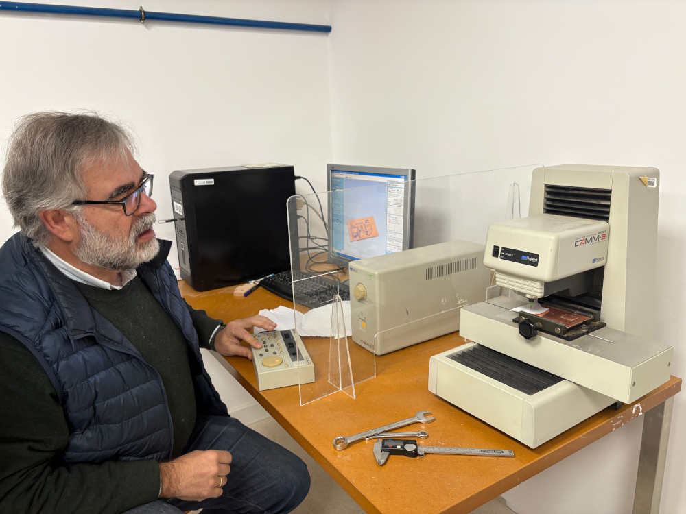
The documentation is on the group page:
Group assignment link, click here
Individual Assignment
Adding a button to the previous PCB I did on week 6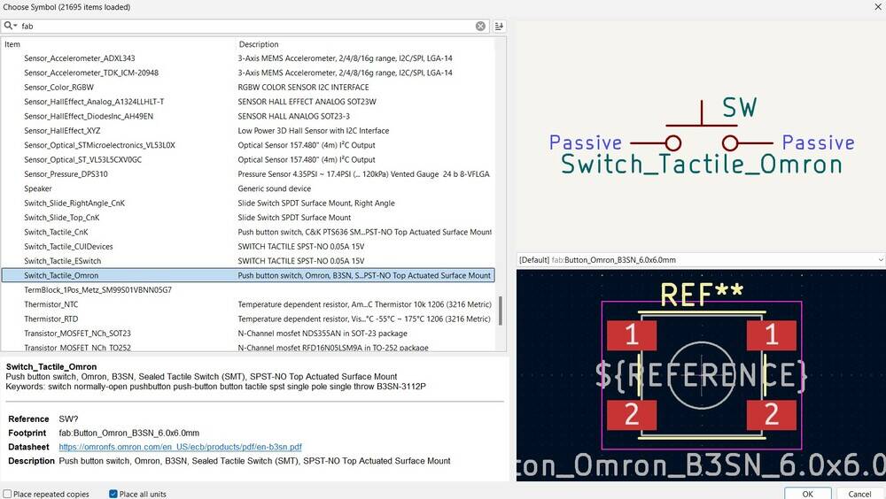
Connect the button to pin D8, this is very important because then you have to know where to solder.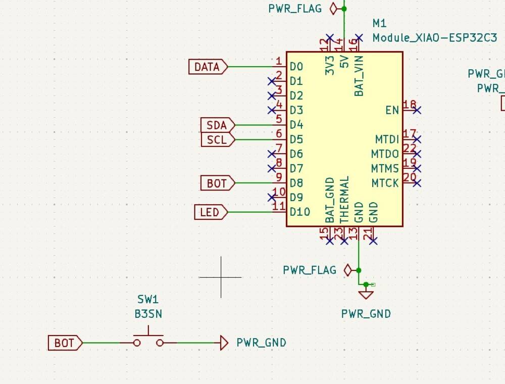
Check if there are no errors, in this case there are not.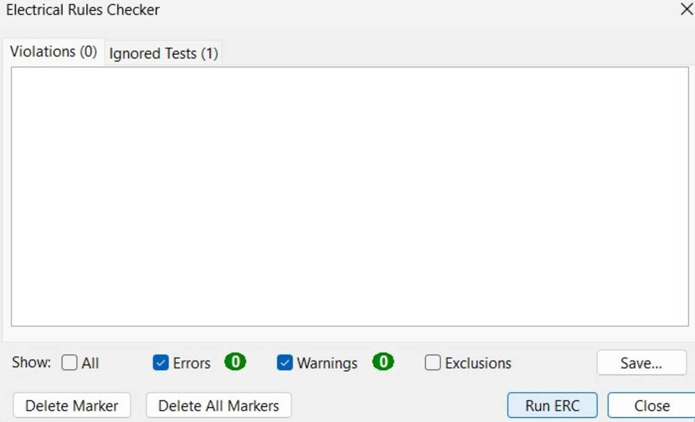
Send the pcb updated to the editor.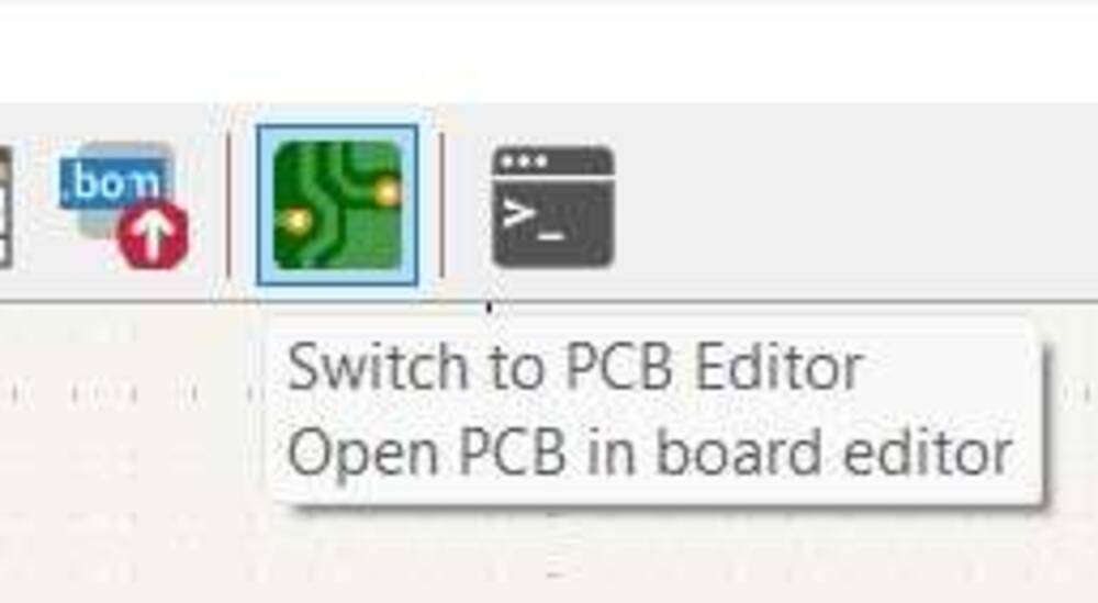
Press this button to update the editor.
On the right of the pcb there us the button located. It looks bigger than in reality.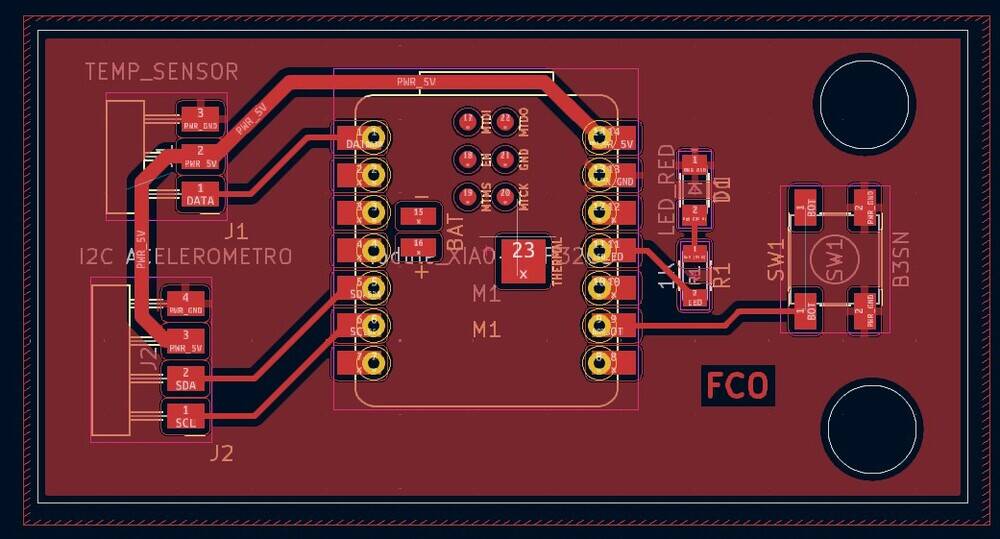
I switch pin to have ine more free.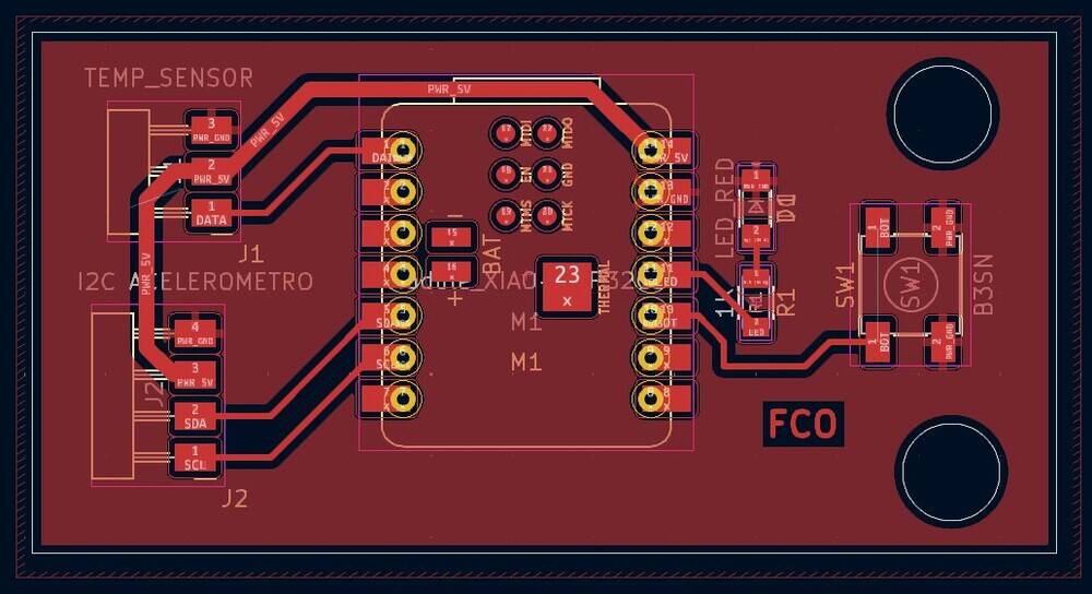
GIMP
Then I had to do some arrengements to the pcb to fabricate it.
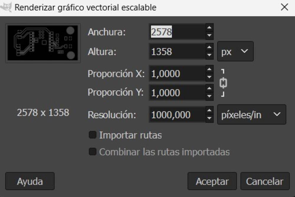
Note
Import it with 1000 px/in resolution.
On the following secuence I changed the color of the background, following the next steps.
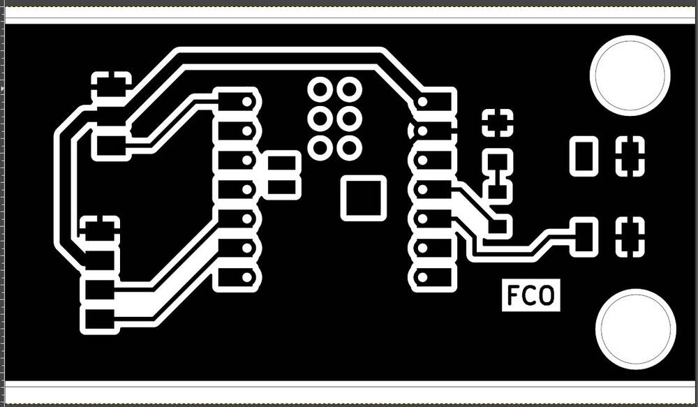
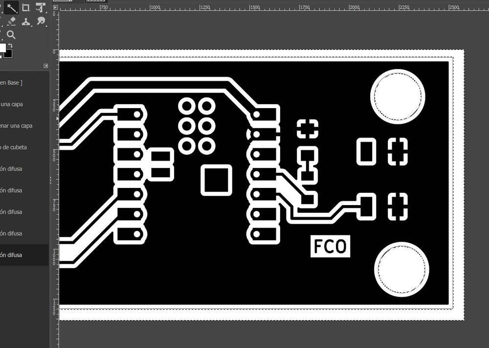
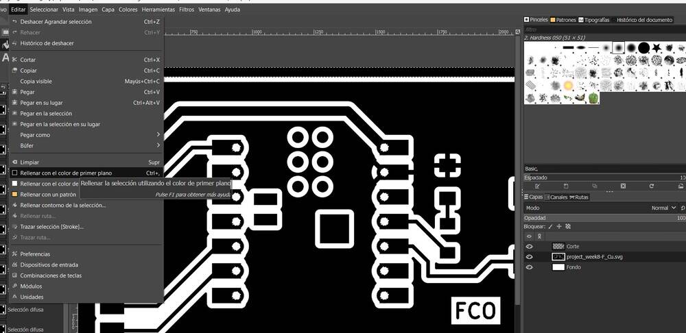
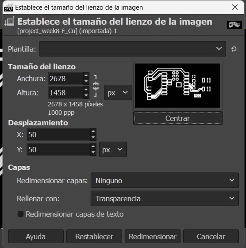
Then change the size of the image to just the pcb.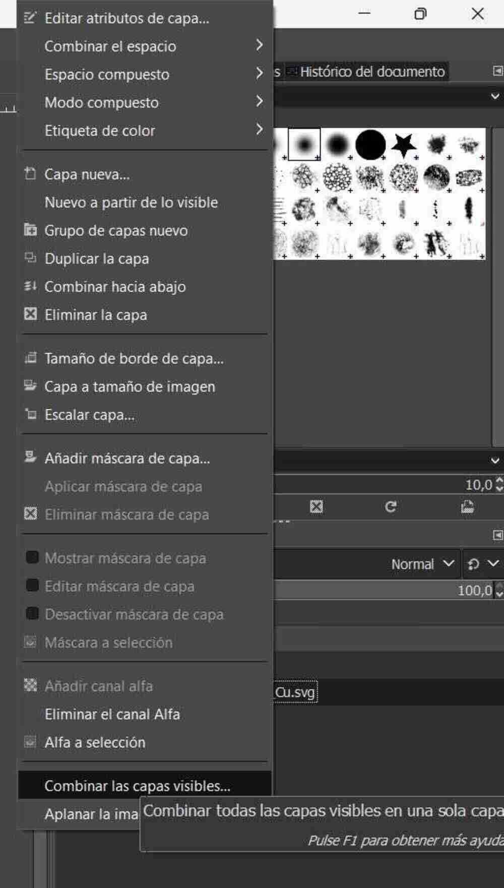
Combine layers and repeat changing removing the background.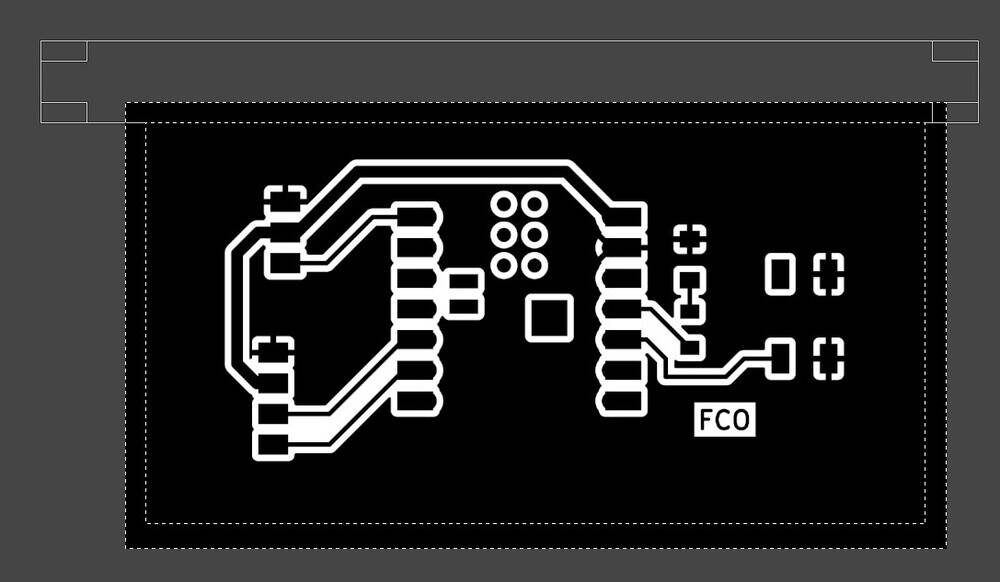
Change the layer size to the same size of the image.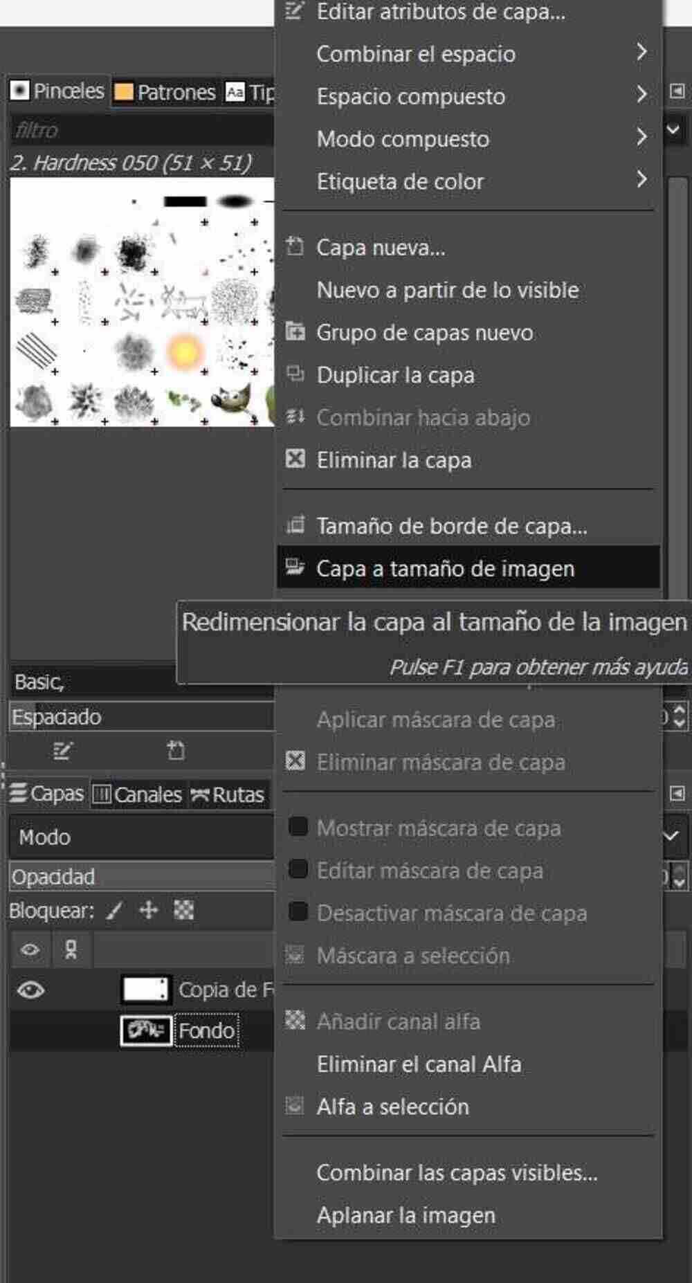
Invert colors.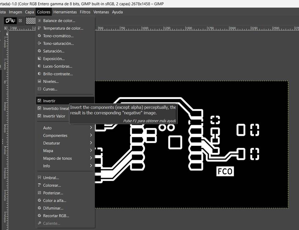
PCB design ready.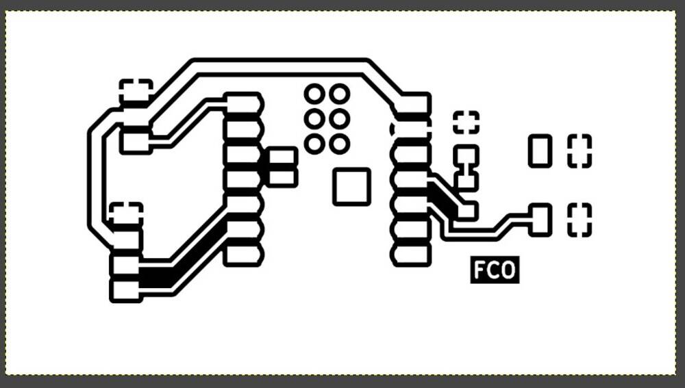
Take note to the background size to put then on VCarve.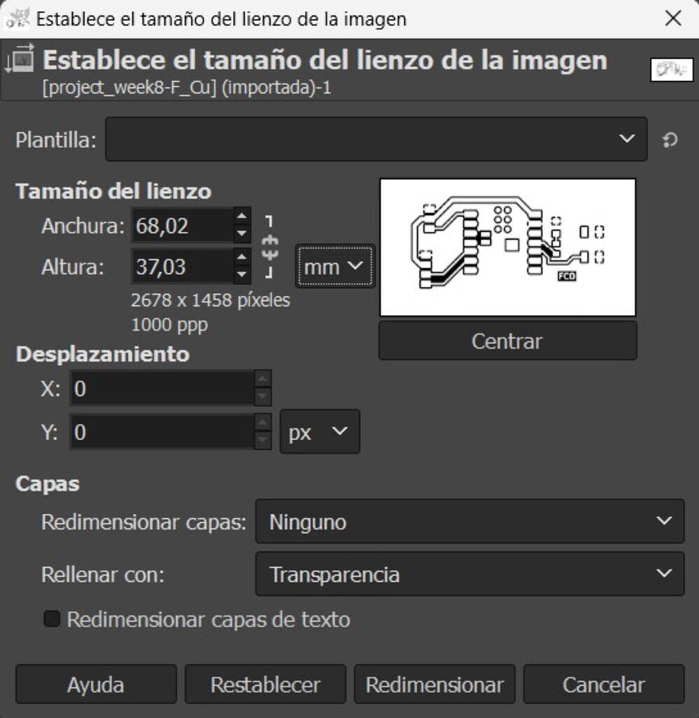
Export image as PNG.
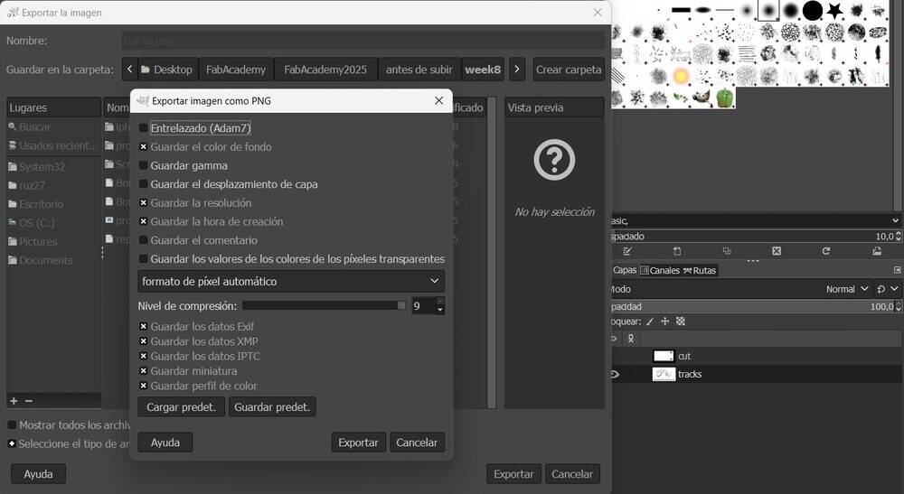
VCarve
Open VCarve and put the size of the pcb rounded to an inter number.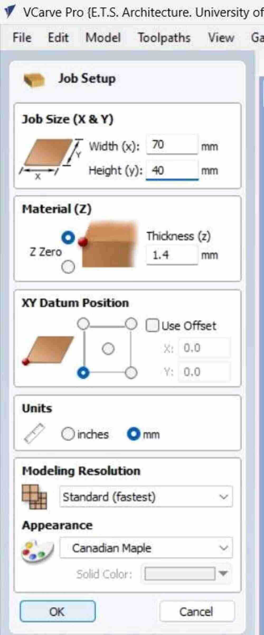
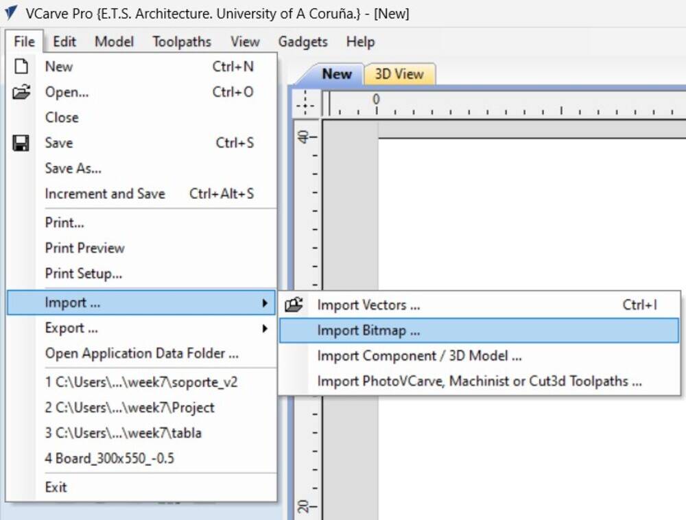
Import bitmap.
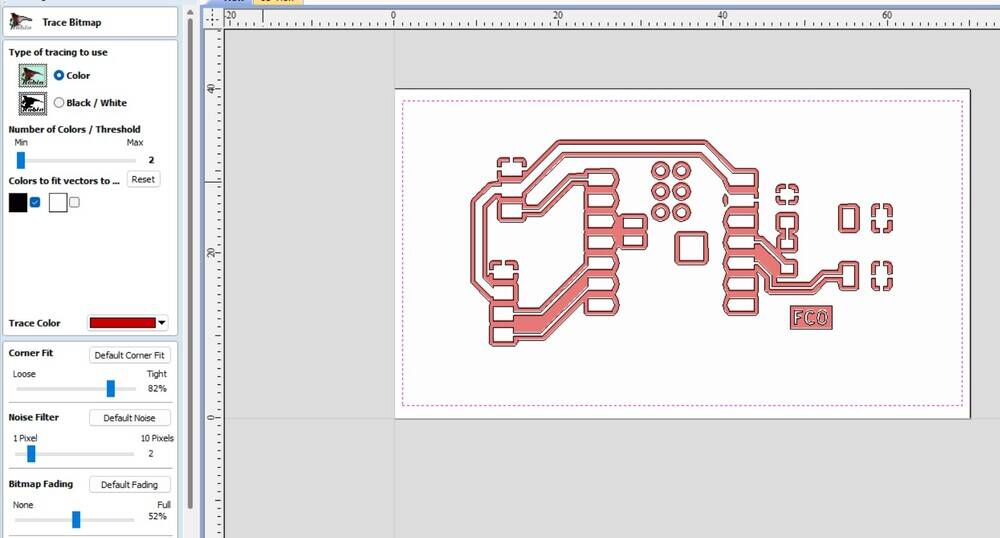
Trace bitmap so the image PNG change to vector.
Select the tool pocket for wrtiting the toolpath.
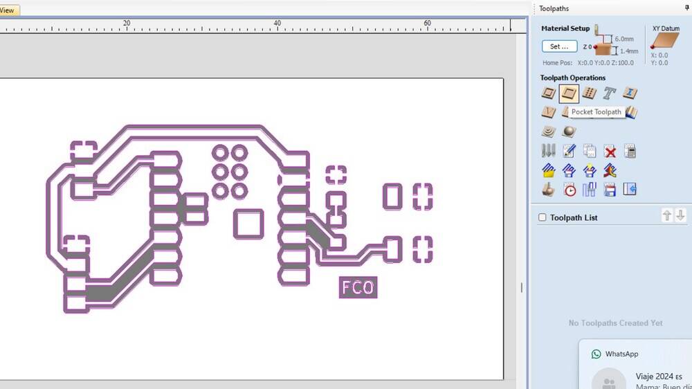
Select or add a new tool for the job.
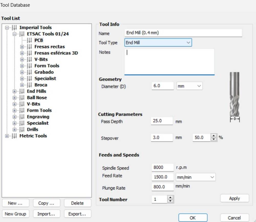
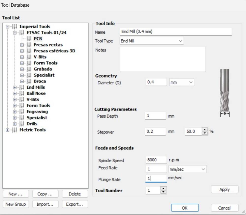
In this case I add a copy and did some modifications
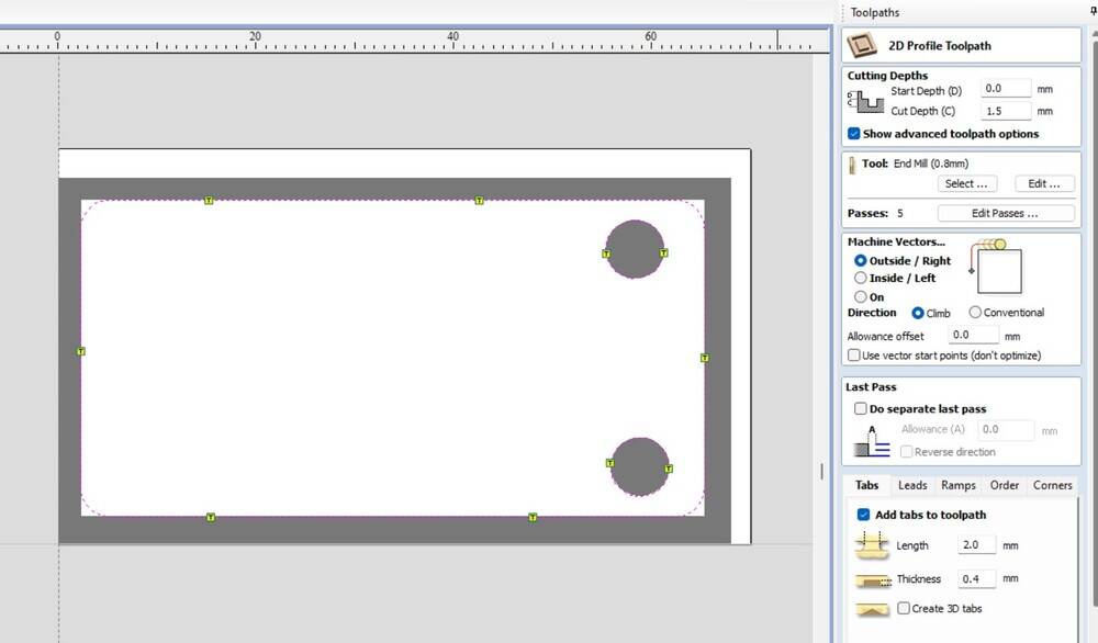
Finally I add some fillets to the board and and ramps.
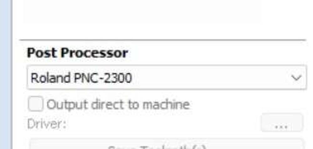
Esport the file to the CNC.
Solder
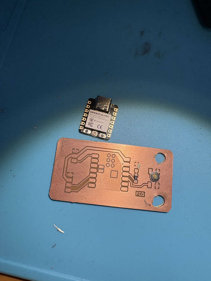
Atfer milling, carefully take out the pcb

Put the components on top and prove it matches.

I put a tape on top of the pins I didn’t use that are at the back of the microcontroller.
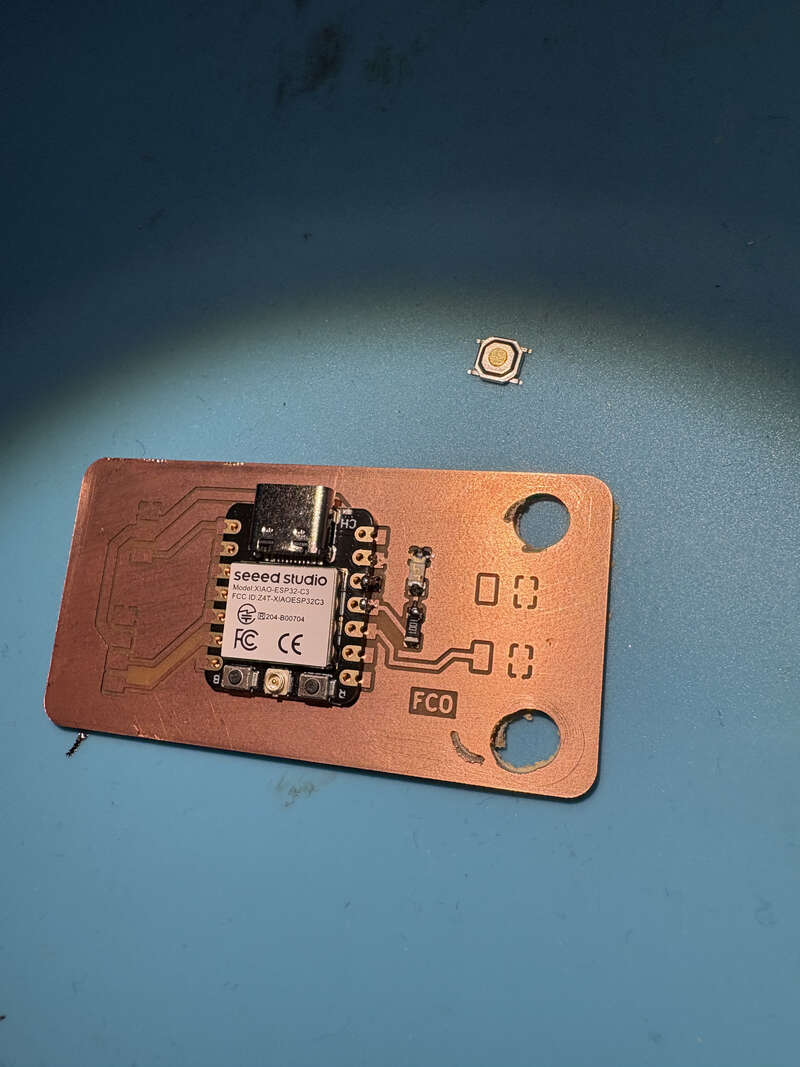
I solder the microcontroller and the led light with its resistence.
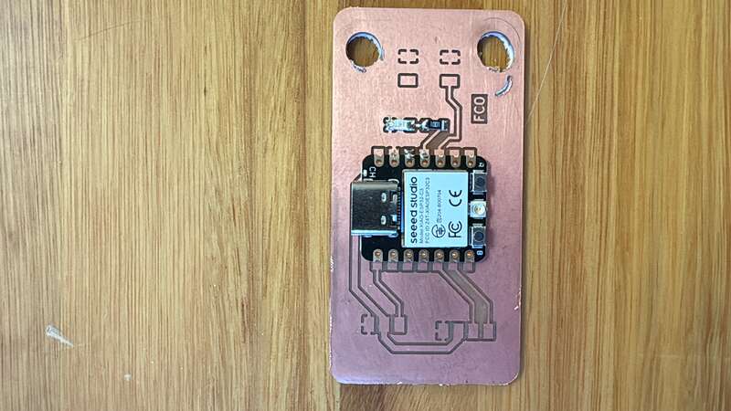
With the PCB ready I try it with arduino IDE.
Arduino IDE
To program the microcontroller on Arduino IDE I tried a basic example. Blink. which is on the following option.

// the setup function runs once when you press reset or power the board
void setup() {
  // initialize digital pin LED_BUILTIN as an output.
  pinMode(D10, OUTPUT);
}

// the loop function runs over and over again forever
void loop() {
  digitalWrite(D10, HIGH);  // turn the LED on (HIGH is the voltage level)
  delay(1000);                      // wait for a second
  digitalWrite(D10, LOW);   // turn the LED off by making the voltage LOW
  delay(1000);                      // wait for a second
}
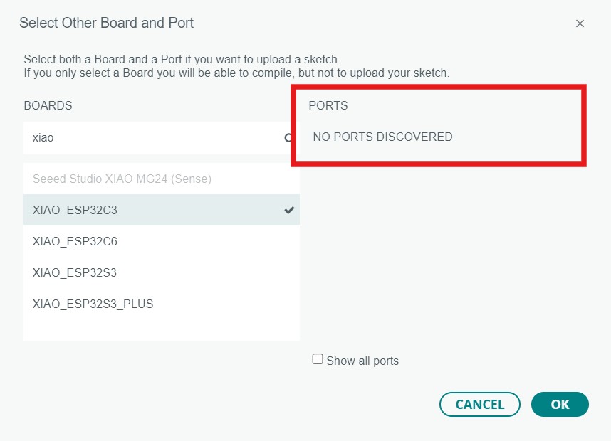
Here select the port which appears something like COM_something depending on the microcontroller.
Veryfi with the blue button and send it to the pcb with the red button:

And finally watch the pcb function:
Learning Oucomes:
The learning outcomes of this assignment included enhancing skills in PCB design and modification, improving proficiency in software tools such as GIMP and VCarve for image editing and vector tracing, and gaining hands-on experience in CNC milling and soldering electronic components. Additionally, I strengthened my knowledge of programming microcontrollers using Arduino IDE, particularly in configuring pins, writing code, and troubleshooting potential errors to ensure the proper functionality of the PCB.
Documentation
- Blink: .zip click here
- Individual project: .zip click here