week 4 Embedded programming
Group assignment:
Demonstrate and compare the toolchains and development workflows for available embedded architectures.
Individual assignment:
Browse through the data sheet for your microcontroller write a program for a microcontroller, and simulate its operation, to interact (with local input &/or output devices) and communicate (with remote wired or wireless connections).
Resume:
In our group assignment, each member gathered information about the available microcontrollers in the lab, such as the Attiny 412 and 1624, RP 2040, and Xiao ESP32C3 and ESP32C6. I focused on compiling details about the RP2040, which is well-suited for applications like wearable electronics, portable data loggers, real-time signal processing, custom communication automation, and IoT prototypes, despite lacking built-in Wi-Fi.
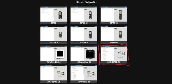
For the individual assignment, I built a circuit with an ESP32C3 where pressing a button turns on an LED of the same color. I did not need to use any external libraries and worked with the microcontroller’s basic components and programming structure, learning how to use buttons and LEDs with the ESP32C3 through the Arduino IDE. I also simulated the circuit in Wokwi before finalizing the design.
Group Assignment
This week, for our group assignment, we each compiled information about one or more microcontrollers available in the lab. The microcontrollers we have are:
- Attiny 412 and 1624
- RP 2040
- Xiao ESP32C3 and ESP32C6
You can find more details about the assignment here:Link to week 4 group assignment
I specifically worked on compiling the RP2040 information, here I includ a summary of the most important details about this component, the most important piece of information is the following pinout image.
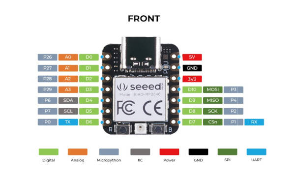
Overall, the recommendation after the analysis is that this component is well-suited for the following applications:
- Wearable Electronics (Small size, good processing power)
- Portable Data Loggers (Fast processing, real-time capabilities)
- Real-time Signal Processing (Audio synthesis, LED animation)
- Custom Communication Automation (High-speed control loops)
- IoT Prototypes (Though it lacks built-in Wi-Fi, it can connect via external modules)
Individual Assignment
Arduino
On Thursday, the day after, we had our weekly FabAcademy class. Luis, our instructor, came to the Fab to teach us about microcontroller architecture and programming. And it was really helpful since we have all this material:
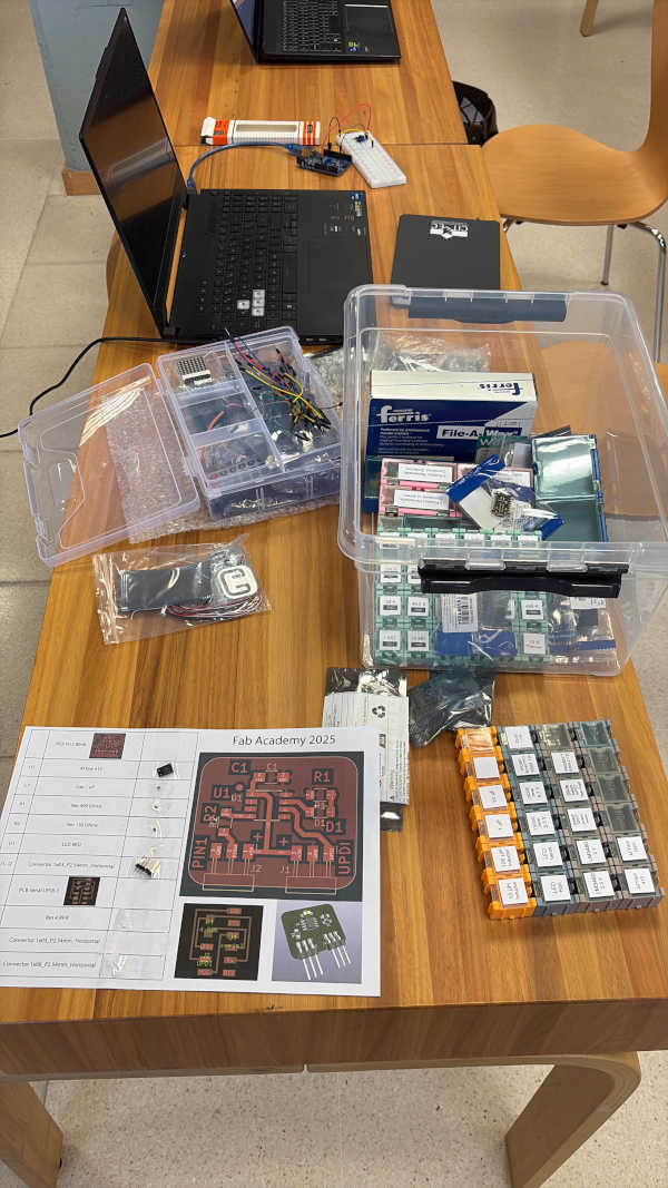
What we first did was a program in Arduinouno to turn a led light on and off. We started by learning about the basic components needed for each microcontroller (capacitors, resistors, breadboards, microcontrollers, etc.).
Then, we downloaded the Arduino IDE from its official website:
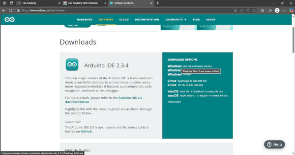
And following Luis we did our first program… we were learning not just how electronic works, but also programming as we work The strcutrue of C it is the following:
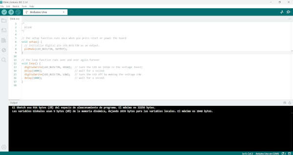
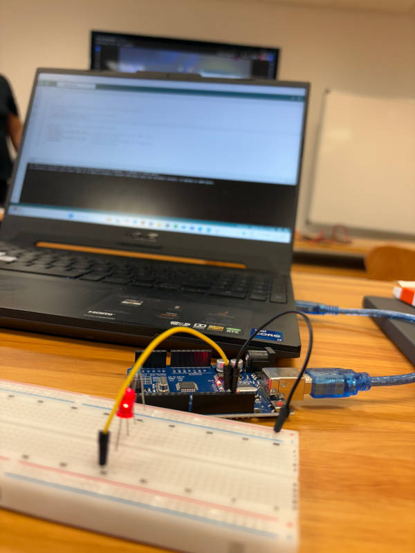
Second we put a push button to turn on the light. The files can be found at the bottom of this page in Documents.
Second program:
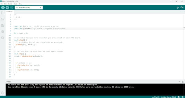
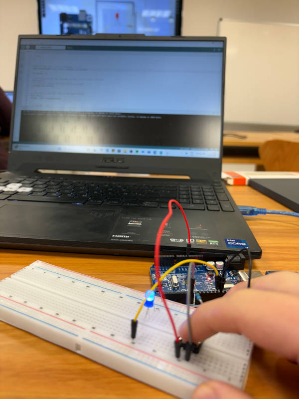
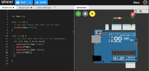
Once we had more less idea what we were doing, it was time to simulate and complete the expected output for the week, so Luis though us how to simulate in wowki:
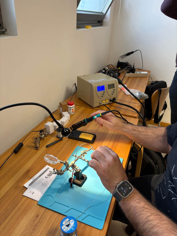
Finally Luis thought us to solder tiny components for the microcontroller and PCB we will use in the future.
Important to mention the temperature was 300°C. Eventhough, tin melts between 210°C and 230°C, and the soldering iron should be set between 260°C and 350°C. For other alloys, more or less temperature may be required.
For my individual assignment, I wanted to go further with what we learned, so I tried to create a circuit in which pressing a button would turn on an LED of the same color as the button.
I also wanted to use a different microcontroller instead of the Arduino Uno, so I decided to use the ESP32C3.

//Pins are defined here(defined as a integer constant and not a variable)
const int buttonRed = D9;
const int buttonGreen = D8;
const int buttonBlue = D7;

const int ledRed = D2;
const int ledGreen = D3;
const int ledBlue = D4;

void setup() {
Serial.begin(115200); //Starts serial communication at 115200 baud rate
Serial.println("Ready"); //Prints Ready when the program has started successfully

pinMode(buttonRed, INPUT);  // When the button is not pressed, the pin reads HIGH (due to the pull-up resistor)
pinMode(buttonGreen, INPUT);
pinMode(buttonBlue, INPUT);

pinMode(ledRed, OUTPUT); //This allows the microcontroller to control the LEDs by setting them HIGH (turning them on) or LOW (turning them off)
pinMode(ledGreen, OUTPUT);
pinMode(ledBlue, OUTPUT);

digitalWrite(ledRed, LOW); //ensures that all LEDs are off at the start of the program
digitalWrite(ledGreen, LOW);
digitalWrite(ledBlue, LOW);
}

void loop() {
bool redState = digitalRead(buttonRed); //reads the current state (HIGH or LOW) of each button
bool greenState = digitalRead(buttonGreen);
bool blueState = digitalRead(buttonBlue);

digitalWrite(ledRed, !redState); //controls each LED by setting it to HIGH (on) or LOW (off)
digitalWrite(ledGreen, !greenState);
digitalWrite(ledBlue, !blueState);

Serial.print("Red: "); Serial.print(!redState); //Prints the LED states (1 for on, 0 for off) to the Serial Monitor
Serial.print(" Green: "); Serial.print(!greenState);
Serial.print(" Blue: "); Serial.println(!blueState);

delay(100);
}{
"version": 1,
"author": "Uri Shaked",
"editor": "wokwi",
"parts": [
{ "type": "board-xiao-esp32-c3", "id": "esp", "top": 38.97, "left": 13.78, "attrs": {} },
{ "type": "wokwi-led", "id": "led1", "top": 6, "left": -73, "attrs": { "color": "red" } },
{
"type": "wokwi-resistor",
"id": "r1",
"top": 147.95,
"left": -57.6,
"attrs": { "value": "1000" }
},
{
"type": "wokwi-led",
"id": "led2",
"top": 15.6,
"left": -101.8,
"attrs": { "color": "green" }
},
{
"type": "wokwi-resistor",
"id": "r2",
"top": 167.15,
"left": -57.6,
"attrs": { "value": "1000" }
},
{ "type": "wokwi-junction", "id": "j1", "top": 148.8, "left": 24, "attrs": {} },
{
"type": "wokwi-led",
"id": "led3",
"top": 25.2,
"left": -130.6,
"attrs": { "color": "blue" }
},
{
"type": "wokwi-resistor",
"id": "r3",
"top": 186.35,
"left": -57.6,
"attrs": { "value": "1000" }
},
{
"type": "wokwi-pushbutton",
"id": "btn1",
"top": -70.6,
"left": 240,
"attrs": { "color": "green", "xray": "1" }
},
{
"type": "wokwi-pushbutton",
"id": "btn2",
"top": 44.6,
"left": 307.2,
"attrs": { "color": "blue", "xray": "1" }
},
{
"type": "wokwi-pushbutton",
"id": "btn3",
"top": 179,
"left": 288,
"attrs": { "color": "red", "xray": "1" }
},
{
"type": "wokwi-resistor",
"id": "r4",
"top": -34.45,
"left": 124.8,
"attrs": { "value": "1000" }
},
{
"type": "wokwi-resistor",
"id": "r5",
"top": 42.35,
"left": 211.2,
"attrs": { "value": "1000" }
},
{
"type": "wokwi-resistor",
"id": "r6",
"top": 176.75,
"left": 172.8,
"attrs": { "value": "1000" }
}
],
"connections": [
[ "esp:D2", "led1:A", "green", [ "h0" ] ],
[ "led1:C", "r1:1", "black", [ "v0" ] ],
[ "esp:D3", "led2:A", "green", [ "h0" ] ],
[ "led2:C", "r2:1", "black", [ "v0" ] ],
[ "r2:2", "j1:J", "black", [ "v0", "h27.6" ] ],
[ "j1:J", "r1:2", "black", [ "v0" ] ],
[ "esp:GND", "j1:J", "black", [ "h19.82", "v86.4" ] ],
[ "led3:A", "esp:D4", "green", [ "v0" ] ],
[ "led3:C", "r3:1", "black", [ "v0" ] ],
[ "j1:J", "r3:2", "black", [ "v0" ] ],
[ "esp:5V", "r4:1", "red", [ "h0" ] ],
[ "esp:5V", "r5:1", "red", [ "h0" ] ],
[ "esp:5V", "r6:1", "red", [ "h0" ] ],
[ "r5:2", "esp:D7", "blue", [ "v0" ] ],
[ "r6:2", "esp:D9", "blue", [ "v0" ] ],
[ "r4:2", "btn1:1.l", "blue", [ "v-48", "h56.4" ] ],
[ "r5:2", "btn2:1.l", "blue", [ "v0" ] ],
[ "r6:2", "btn3:1.l", "blue", [ "v0" ] ],
[ "btn1:2.r", "esp:GND", "black", [ "h0" ] ],
[ "btn2:2.r", "esp:GND", "black", [ "h0" ] ],
[ "btn3:2.r", "esp:GND", "black", [ "h0" ] ],
[ "r4:2", "esp:D8", "blue", [ "v0" ] ]
],
"dependencies": {}
}pinMode(buttonRed, INPUT);In this case, the buttons are connected to GND with an external pull-up resistor, so:
When the button is not pressed, the pin reads HIGH (due to the pull-up resistor). When the button is pressed, the pin reads LOW (because it connects directly to GND).
If you were using the ESP32’s internal pull-up resistors, you would use INPUT_PULLUP instead:
pinMode(ledRed, OUTPUT);sets the LED pins as outputs. This allows the microcontroller to control the LEDs by setting them HIGH (turning them on) or LOW (turning them off).digitalWrite(ledRed, LOW);ensures that all LEDs are off at the start of the program. Since the LEDs turn on when the pin is set to HIGH, setting them to LOW makes sure they start in an off state.digitalRead(pin);reads the current state (HIGH or LOW) of each button. The result is stored in boolean (bool) variables: redState → Button Red state greenState → Button Green state blueState → Button Blue state Since the buttons are wired with pull-up resistors, they behave as follows: Not pressed → HIGH Pressed → LOWdigitalWrite(pin, value);controls each LED by setting it to HIGH (on) or LOW (off). The ! (NOT) operator is used to invert the logic: If redState is LOW (button pressed), !redState is HIGH, turning the LED on. If redState is HIGH (button not pressed), !redState is LOW, turning the LED off. This ensures that pressing a button turns on the corresponding LED.Prints the LED states (1 for on, 0 for off) to the Serial Monitor. Since the button logic is inverted, we also print !redState, !greenState, and !blueState so the Serial Monitor correctly reflects the LED states
Note
It wasn’t necessary to add any libraries.
Also, if you’re interested in how the button works, here is a detailed explanation of how the component functions.
Learning Oucomes:
Through this week’s group and individual assignments, I learned how to gather and analyze technical information about microcontrollers, specifically focusing on the RP2040 and ESP32C3. I gained hands-on experience in microcontroller architecture and programming, learning how to control LEDs and buttons using the Arduino IDE. Additionally, I explored circuit simulation in Wokwi and practiced using basic electronic components like resistors and capacitors. The assignments also helped me understand how to work with different microcontrollers, expanding my skills in both hardware and software aspects of embedded systems.
Documentation
- program 1: .ino click here
- program 2: .ino click here
- program 3: .ino click here
- Project click here