week 3 Computer-Controlled Cutting
Group assignment:
- Do your lab’s safety training
- Characterize your lasercutter’s focus, power, speed, rate, kerf, joint clearance and types.
- Document your work to the group work page and reflect on your individual page what you learned.
Individual assignments
- Design, lasercut, and document a parametric construction kit, accounting for the lasercutter kerf, which can be assembled in multiple ways.
- Cut something on the vinyl cutter.
Resume:
At ETSAC, I worked with my group to update the cutting values of a laser cutter that had recently undergone maintenance, including a new laser cannon and mirrors. On the first day, we characterized one material with a press-fit test, where I helped Pablo design a parametric model. My design was used to check the initial parameters, and I was responsible for printing and refining the model. After testing, we determined that the best fit was 5.05mm for 5mm MDF.
For my individual assignment, I planned to create a scale model to support pieces for my final project. Since the structure needed to be highly rigid and flexible in design, I initially used Grasshopper but later switched to manual nesting in Rhino for efficiency. During fabrication, I encountered some issues, such as broken and poorly cut pieces, which helped me refine the process.
For the vinyl cutter, I printed and cut logos, configuring the machine with parameters: pressure 20, velocity 3, passes 1, and cutting depth 4. The final product turned out well after calibration and adjustments.
Group Assignment
At ETSAC, there is a laser cutter that has been in use for a long time. In December of the previous year, it underwent a full check-up, during which the laser cannon and mirrors were replaced. The new cannon has significantly different power compared to the previous one, so our mission was to update the cutting values accordingly.
On the first day of work, while our instructor was with us, we characterized just one material by performing a press-fit test. You can see the entire activity on the group page. In summary, we collaborated to design a parametric press-fit, where I assisted Pablo with the design.
My design was the one used to check the initial parameters.
For the group assignment, my tasks began when each of us created a press-fit model to characterize the laser machine. My role was to print and refine it. Additionally, I helped Pablo with the parametric design of the press-fit. You can see an image of the instrument here:

Link to week 3 group assignment
Individual Assignment
Laser Cutter Machine
I wanted to create a scale model for the support of the pieces that will be cut in the future during the final assignment. I hope to complete this during the CNC machining week, provided the materials are available. Some key constraints and considerations for this project are as follows:
It is important to adress that this idea or necessity originated on the final project page, where I explained more details about the project.
- Since the program is designed for a workflow, it will have very different outputs, so I needed to create something parametric with as many adjustable variables as possible.
- The structure had to be highly rigid in all directions due to the robotic arm’s forces. The next day, when Luis came to our lab, it was time to put what we had learned into practice. First, we had to repeat the initial activity we had done before. To do this, I reused the press-fit model we had. I opened the Grasshopper file and adjusted the width to match the thickness of the material involved, which was wodden MDF 5 mm.
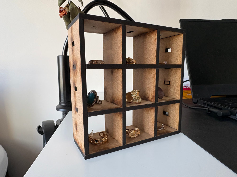
Box
In order to complete the assignment I did a box with a parametric code which has important variables like material thickness and kerf. Which you can see the process in the following images.
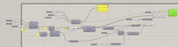
Parametric code:
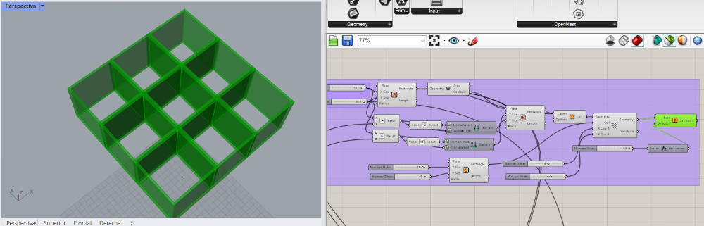
You can see at the top of the image that I have the two variables: material thickness and kerf or tolerance.
So first i did the kerf material:
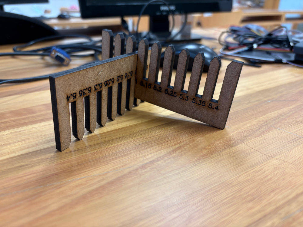
The fit was best at 5.05 mm and the thickness of the material is 5 mm.s
This is the result. The process is on the group page.
other project
On the grasshopper I used the following parameters for the kerf test:
Here I start with the initial thickness and used 9 more thickness adding 0.05 mm each.
This is the parameter that imputs the height of the rectangles.
Finally I input the text location.
Some restriction is that in the middle there has to be the thickness of the material and then I put +-0.05 mm 4 times. resulting in the next instrument

I used with an already programed in Corel a simulation of how it would work and calibrating the machine, the hole process can be found in the group assignment page
First I did some test to calibrate the parameters on the machine
The result was that the best fit is 5,05 mm og width each space
Having that information I proceed to do the pieces. The grasshopper is very complex and large so if you have interest on having more information about you can download the file from the additional document part at the bottom of this page.


Then, I reliazied it was inconvenient to do the hole model in grasshopper, i prefer to go to rhinoceros and do manually a sort of nesting. It is much more quick to parametrize verything
You can see the images here of the final product


Learnings:
Taking out the pieces I broke and also there was pieces that didn’t cut well.

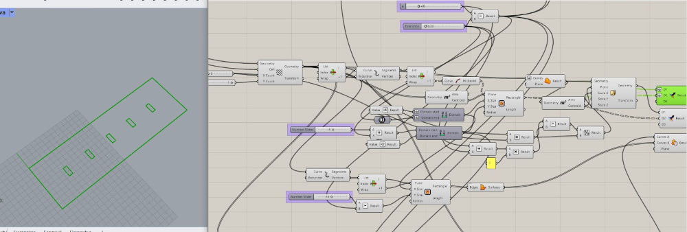
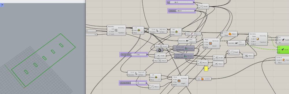
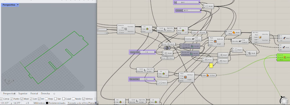
Finally to complete the individual assignments I did a modular construction kit. the code is the following:

And the modules look like this in rhino after a little postparametrization I change the layers and use the command _Extractwire in rhino to have the contour. YOu can do this step in different ways, for instance, the button on the left menu that has a white contour.

Then it was time to cut …

Finally I just take the pieces out the board and assemble them:


Vinyl Cutter Machine
For the vinyl cutter Luis brought us printed our logos and we cut it in the vynil cutter machine.
- First I needed the logos with the machine configured to the materials we had, and connected by bluetooth with my computer

logos in Silhouette - then I did the contour

contour - offset so the contour exceed a little bit the brwon part

offset - Then we characterize the parameters of the machine
- pressure: 20
- velocity: 3
- passes: 1
- cutting depth: 4

parameters
- Final product

final product - Final product in detail

final product 2
Learning Oucomes:
Through this assignment, I learned the importance of properly calibrating the laser cutter for different materials and how minor adjustments, like a 0.05mm tolerance, can significantly impact the fit. I also realized that while parametric design in Grasshopper offers flexibility, manual adjustments in Rhino can sometimes be more efficient for certain tasks. Additionally, I gained experience in troubleshooting fabrication issues, such as broken or poorly cut pieces. Finally, working with the vinyl cutter reinforced the importance of precise machine settings to achieve clean and accurate cuts.
Documentation
- pressfit: .dwg click here
- Modules: .gh click here
- Modules dxf: click here
- Pressfit cardboard: .dwg click here
- pressfit practice: .gh click here
- modules in rhino: .3dm click here
- support: .3dm click here
- support in dwg: .dwg click here
- logo: .studio3 click here