week 2 Computer-Aided Design
Model (raster, vector, 2D, 3D, render, animate, simulate, …) a possible final project, compress your images and videos, and post it on your class page
Resume:
I started the project by designing a favicon in Inkscape, simplifying the concept and using tools like “Path” to refine the design. Then, I worked on a parametric arch design in Grasshopper/Rhino, adjusting parameters like height and width. Later, I used SolidWorks to create a more professional and detailed sketch of my project and worked on a bridge design in Fusion 360, exporting .STEP files from Rhino. Throughout the process, I experimented with animations and renders and used HandBrake to convert video files. At first, using these programs seemed complex, but with practice, I was able to complete tasks faster and more efficiently.
Inkscape: Favicon
Luis, my local instructor, suggested that we create a favicon for the project. He gave us a brief introduction to Inkscape, and after that, I felt confident enough to dive in on my own.
At first, it wasn’t as easy as I had expected. In my mind, I envisioned a complex concept, but I decided to start simple and see where it led me.
I began with a straightforward approach—drawing a circle and a square, then placing an arch inside them.
To refine the design, I downloaded two images from Google with elegant curves and traced their contours using the pencil tool.

Problem: I couldn’t change the color of the outer lines, so my solution was to set the line width to 0. This effectively made them invisible

I then obtained my first result, which turned out like this:

At first, I wasn’t sure how to fill the shape, but Inkscape is quite intuitive. I explored the options and found that using “Path” > “Fill Between Paths” did the trick.
Then I assembled all the elements and adjusted their placement. This was the final result:

I used the Intersection tool to merge the bridge with the circle and removed the last square

Lastly, I wanted to change the color to one that represents wood. After selecting the right shade, I scaled the design to 512 × 512 px to finalize the favicon
![]()
With that done, I went to favicon.io and uploaded the image. The site generated all the necessary favicon files, ready to be uploaded to the repository.
Grasshopper/Rhino
In this software, I aimed to do parametric design. To start, I kept things simple and gradually increased the complexity of the problem. For this specific project, I wanted to focus solely on parameterizing arches. Here’s how I approached it with the following program:


Here is a sequence of the outputs the algorithm produced:

I want to emphasize that this is a parametric design. By adjusting the parameters (height, width, N° of pieces, span) the result changes, as shown in picture 2:

If you’re wondering how I added the people to the image, I downloaded them from the internet. I’ll upload the file to the repository and the reference.
Finally, I decided to develop my project in the following dimensions:
- L=1800 mm
- H=600 mm
- b=30 mm
- h=50 mm

SolidWorks
At first, I struggled a bit with the installation process because I was trying to download the software directly from the SolidWorks website. Then I realized that FabAcademy had sent us the license code along with the correct page to download the software, which is:
Download SolidWorks for students Installation
Once I had the program running, my focus shifted to developing the Final project sketch in a more professional way. I also aimed to produce the joint and arch plans.


Even though I had the final drawing, I wanted to create a version of the bridge, so I added boards in Rhino to each block of the arch. The result was:

Then, I went through the whole process I described earlier in the final drawing.


Fusion 360
I also wanted to create detailed drawings and further develop the bridge design. So, I downloaded the software and exported the arch from Rhino as a .STEP file. I wasn’t sure how it was going to work since I had never used .step files, but I decided to give it a try.

The result was very good.
I wanted to create a suspension bridge this time, so first, I made a cylinder where a screw would go. At that point, I realized the program wasn’t in English—my bad. But I was so inspired by the process that I decided not to change the language.


Then I did the pinned supports with the next design:


Then, I took out the drawing, and it was very similar to SolidWorks. However, the key difference was the ease of the program. It depends on your previous experience but at least for me Solidworks was easier to work with.

I didn’t like the render in Fusion; the project was very messy, and some items just joined together with dependencies on others, which prevented me from rendering it the way I wanted

After this, I had time to give the bridge design, animation, and render a second try. The second attempt was much more intuitive, and everything came together much smoother.
The second bridge look like this:
How to do it:


Last, I did an animation:

Animation:
Handbrake
I used the program HandBrake. It’s very easy to use and intuitive. I don’t have any extra recommendations. I’m not sure why the .avi file didn’t work for me, so apart from compressing the file, I switched it to .mp4.

GIMP
To compress images is very important to have a well defined process since we upload a lot of images every week.
In my case I decided to use GIMP
GIMP (GNU Image Manipulation Program) is a free and open-source raster graphics editor used for editing, retouching, and manipulating pixel-based images. As a raster-based tool, GIMP works primarily with bitmap images composed of individual pixels, allowing for detailed photo editing, digital painting, and image composition. It supports layers, masks, filters, and a wide range of color adjustment tools, making it a powerful alternative to proprietary raster graphics software like Photoshop.
Raster vs vectorial
Raster images are made up of a grid of individual pixels, where each pixel has its own color and position. Common raster formats include JPEG, PNG, GIF, and BMP. These images are resolution-dependent, meaning they can lose quality or appear pixelated when scaled up.
Vector images, on the other hand, are created using mathematical equations to define geometric shapes like lines, curves, and polygons. They are resolution-independent, meaning they can be scaled infinitely without any loss of quality. Common vector formats include SVG, AI, and EPS.
For this example I will upload an image to this page:
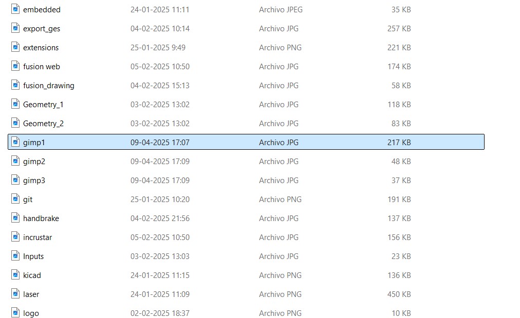
step 1: take a screenshot
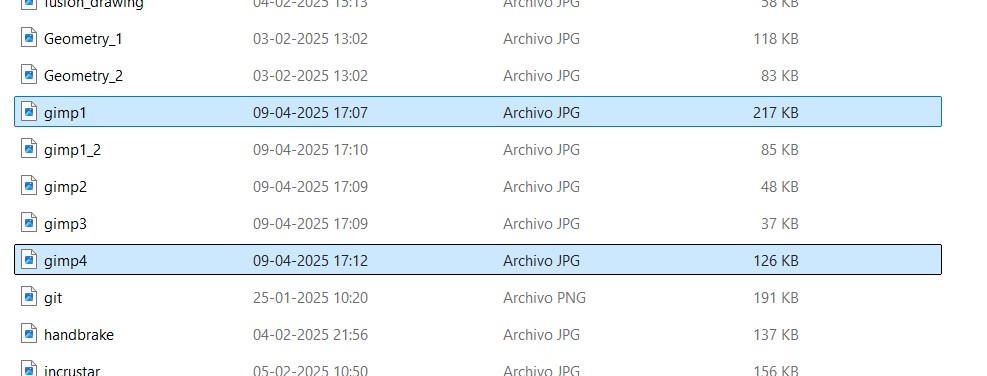
The image weight is:
Open and scale the image:
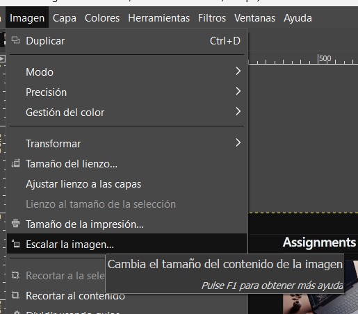
1000 pixels width is enough.
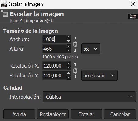
Lower the quality to 70%
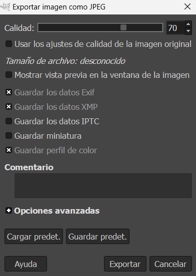
With this steps the image weight decreases to almost half the inital weight.
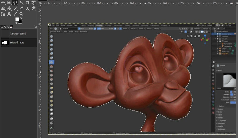
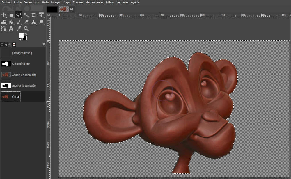
Also I quit the background of an image:
select the free select tool and hand select the part of the picture you want to crop out
First go to layer>transparency>add alpha channel.
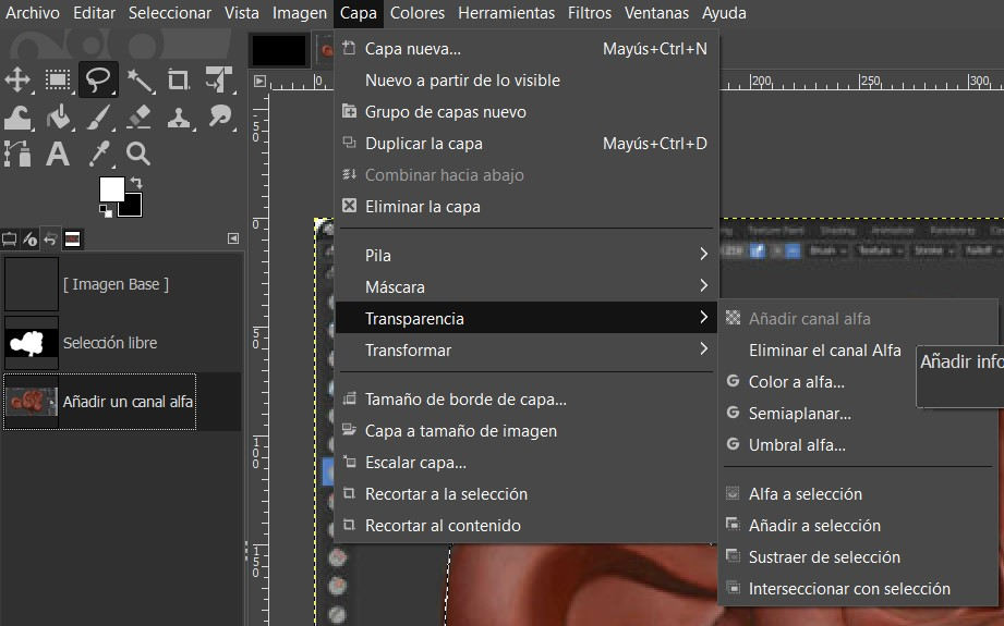 click select>invert and finally press control + x and this will remove the background.
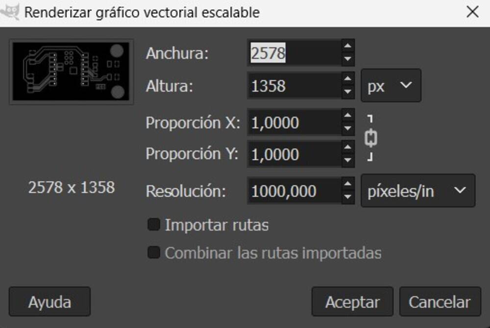
Finally, how to manage a pcb boarde in gimp and then export it to Vcarve as a bitmap.
Then I had to do some arrengements to the pcb to fabricate it.
Note
Import it with 1000 px/in resolution.

On the following secuence I changed the color of the background, following the next steps.


Then change the size of the image to just the pcb.
Combine layers and repeat changing removing the background.
Change the layer size to the same size of the image.
Invert colors.
PCB design ready.
Take note to the background size to put then on VCarve.
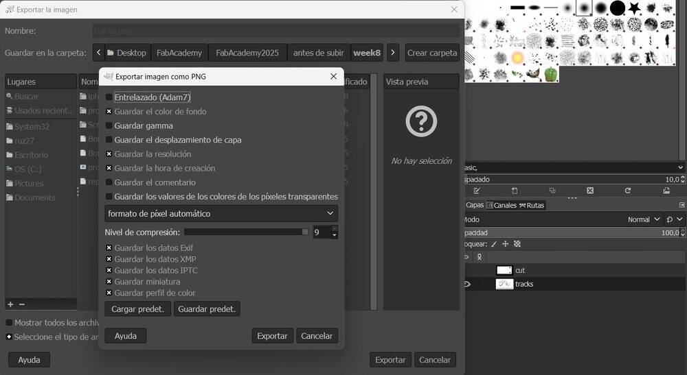
Export image as PNG.
Learning Oucomes:
I developed skills in vector design using Inkscape, parametric modeling with Grasshopper/Rhino, and advanced 3D modeling in SolidWorks. I also worked on bridge design in Fusion 360, learning how to create detailed components and export files between programs. Through animation and rendering, I improved my ability to visualize designs, while managing and converting files efficiently using HandBrake. Overall, I gained experience in adapting to new software, troubleshooting issues, and refining workflows to complete tasks more efficiently and effectively.
Documentation
- Favicon: .svg click here
- bridge1: .stp click here
- bridge2: .stp click here
- solid arch: .stp click here
- Project: .3dmclick here
- 1 block: .sldprt click here
- Drawing: .slddrw click here
- Bridge: .sldprt click here
- Drw bridge: .slddrw click here
- Bridge in fusion: .f3d click here