week 17 Wildcard Week
Design and produce something with a digital process (incorporating computer-aided design and manufacturing) not covered in another assignment, documenting the requirements that your assignment meets, and including everything necessary to reproduce it
Assignment
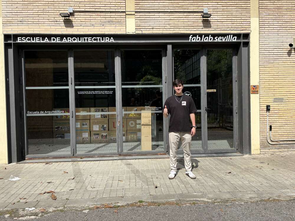
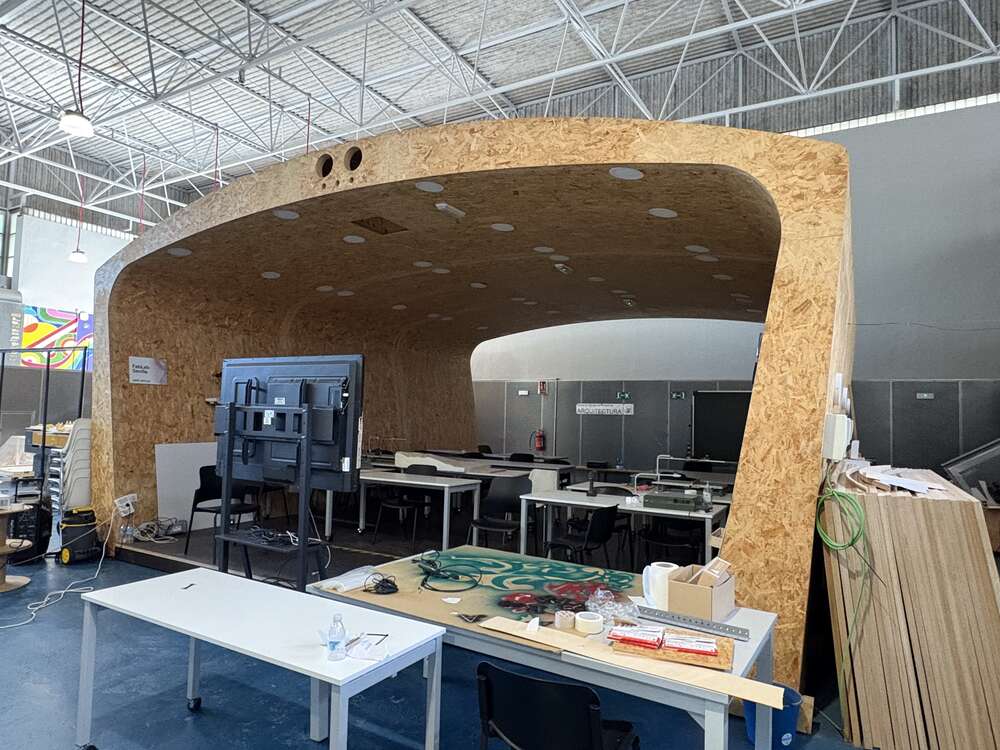
This week, I visited the FabLab at the University of Seville, which is located in a former gymnasium—an ex-polideportivo—so the space was very large. Many things caught my attention; here are a few examples:
- A mobile robotic arm
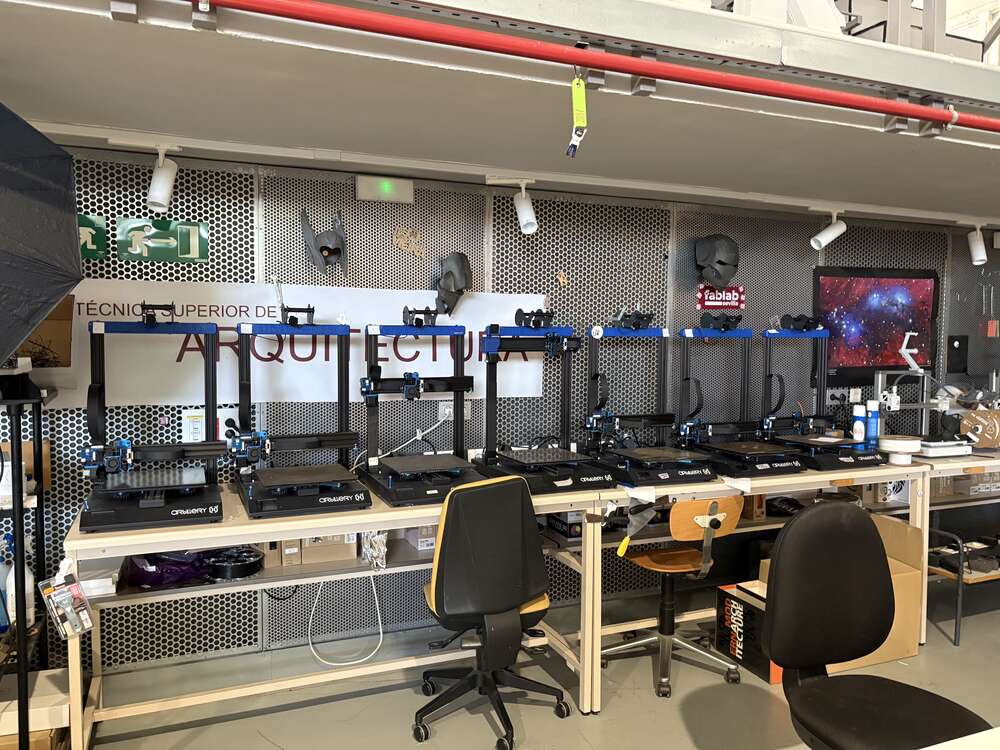
- Numerous 3D printers
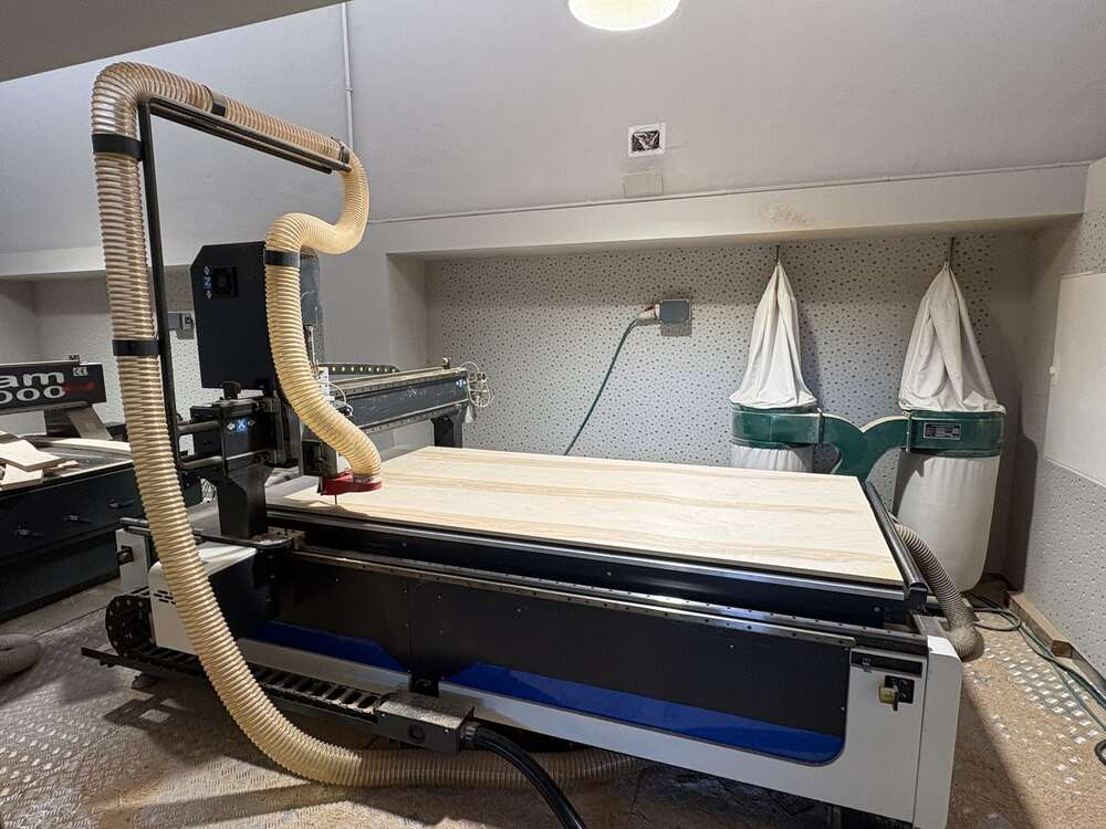
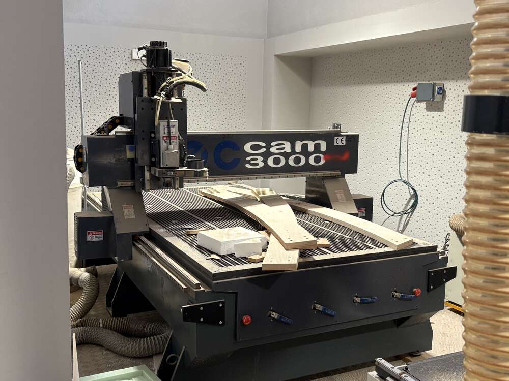
- Two CNC machines
- A spacious classroom
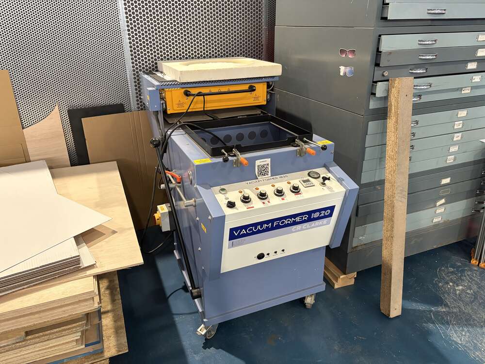
- A thermoforming machine
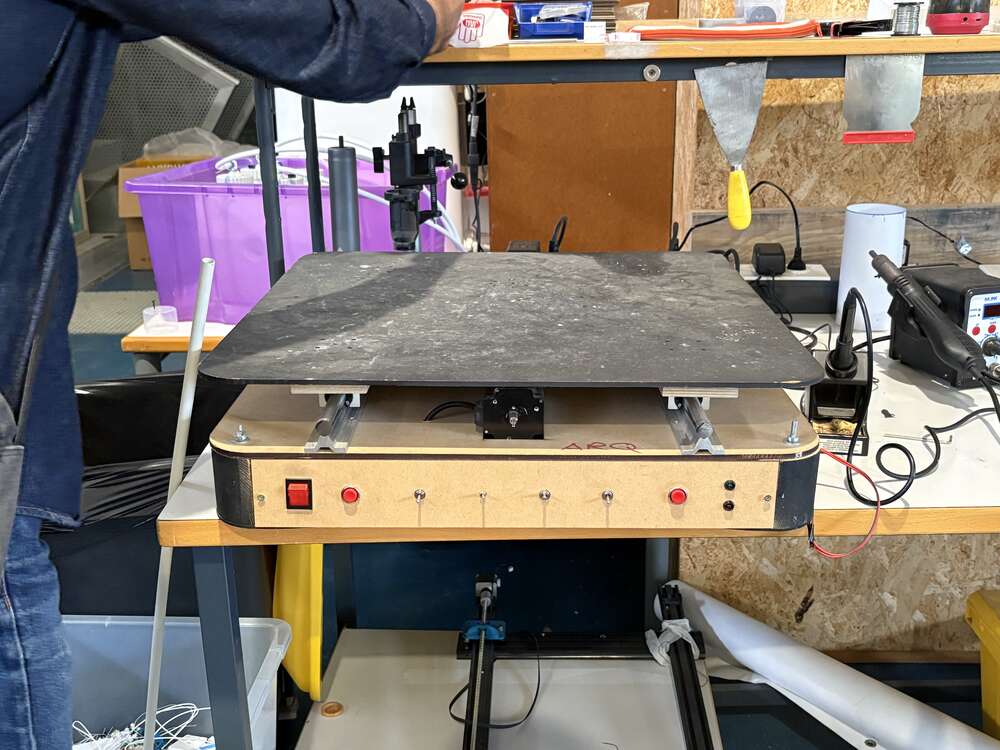
- A DIY vibrating table
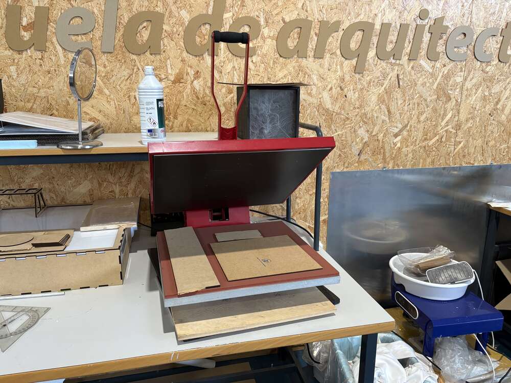
- Heat press machine
The entire space was clean and well-organized, with everything in its proper place.
Here are some images from the visit:
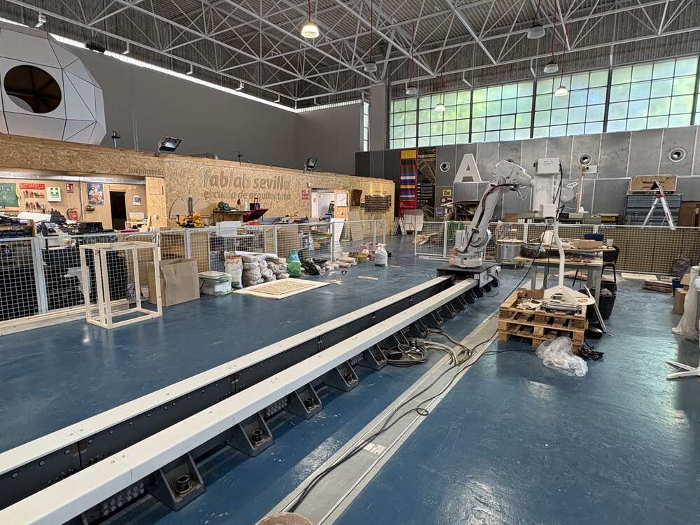
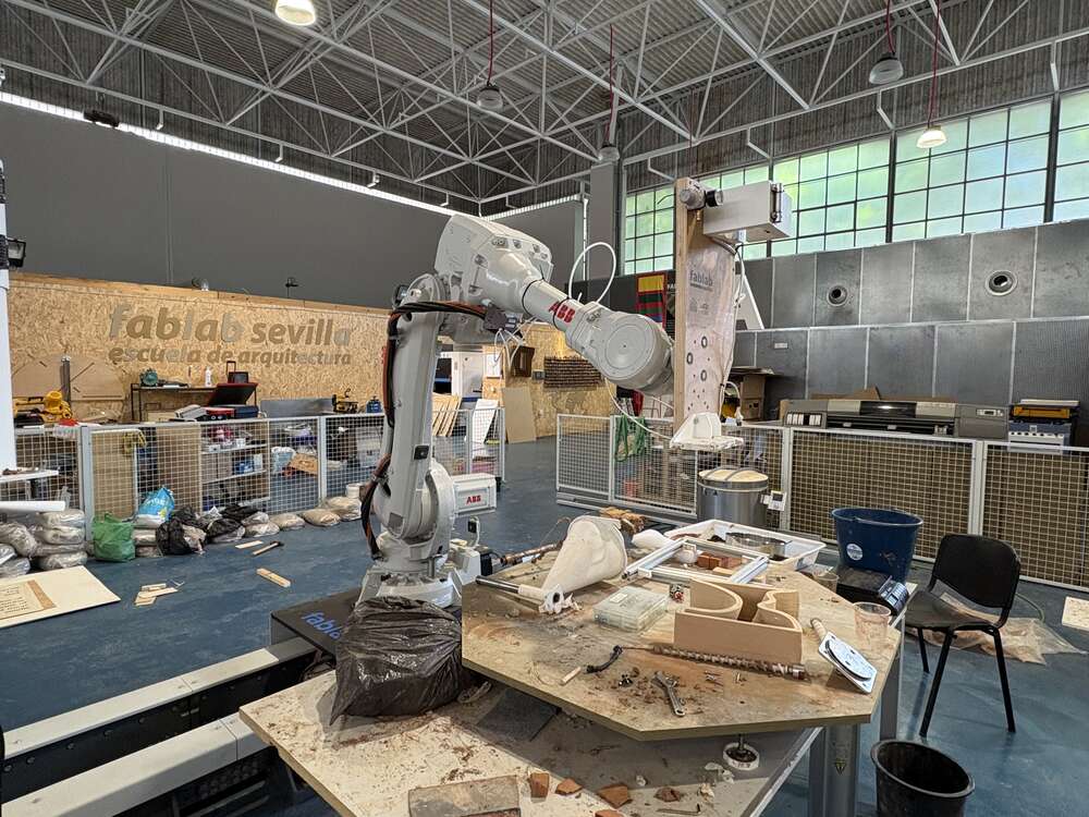
I found the robotic arm to be the most interesting element of the visit. The FabLab staff kindly provided detailed information on how to carry out the entire process. I hope on a future implement the technology at ETSAC.
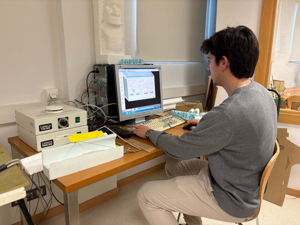
Hot Wire Cutting
To practice with the machine I wanted to do a simple A, for this I followed the instuctions that are on the page of the school.
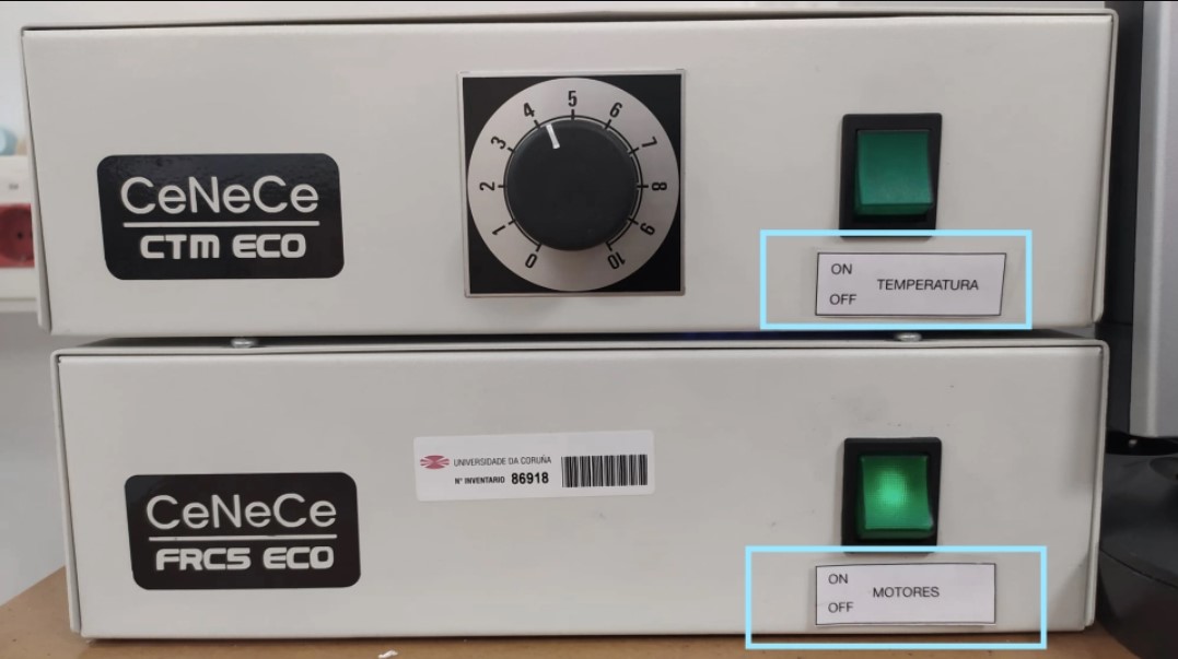
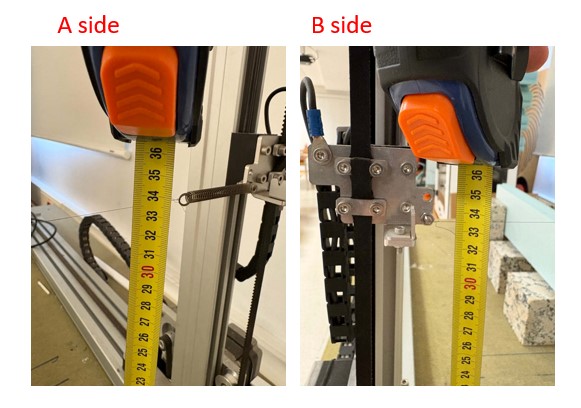
First, turn on the computer and log into the user account. Open the control software (CeNeCe Pro) for the cutting machine. Then, switch on the machine by activating two green buttons: one powers the motors that move the axes, and the other controls the wire’s heating system.
Next, make sure the machine is properly aligned. Check that both ends of the wire are at the same height and position. If they’re not aligned, use the software to adjust the axes until they match. Once aligned, position the wire at a convenient starting point for the cut, or move it to the limits if using the full cutting area.
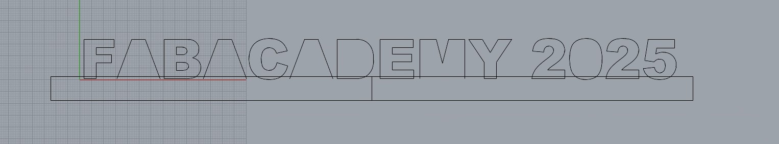
Send your design file (in .dxf format) by email to the lab computer. Open it in the CeNeCe Pro software, scale it if necessary, and define the starting point of the cut. Save the file as a “dat” and assign it to a new or existing family for later use.
Create a new project in the software and assign a default cutting table configuration. Load the family and the corresponding “dat” files for both sides of the cut. Confirm that everything looks correct in the preview.
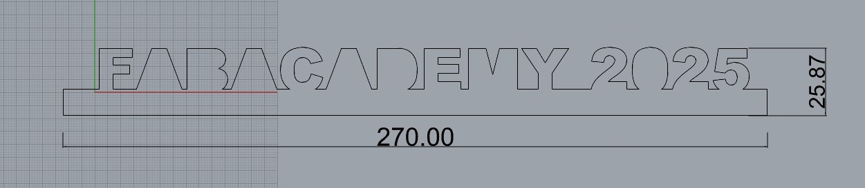
Configure the material block by entering its dimensions and position. Then, set the cut dimensions based on your design, making sure they match for both sides. Select the material from a predefined list, and finally generate the machine control file to prepare for cutting.
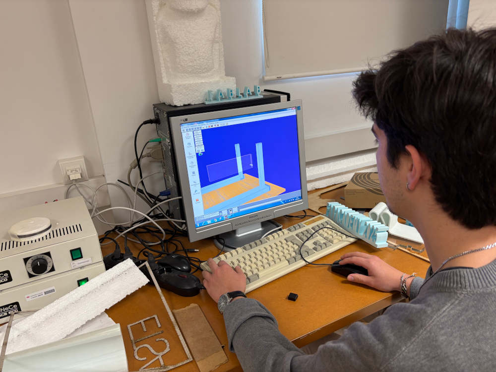
In the “Profile Cut” section, review all cutting parameters. Use the 3D view to confirm the setup. When ready, turn on the heated wire and start the cutting process. You can adjust the cutting speed and temperature for optimal results during the operation.
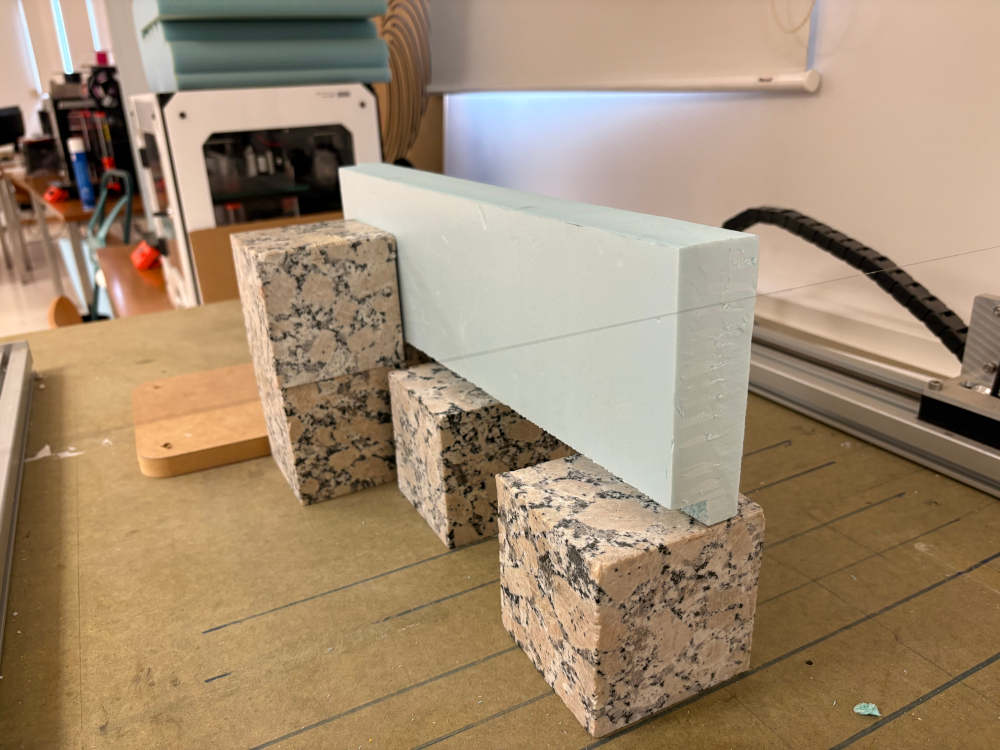
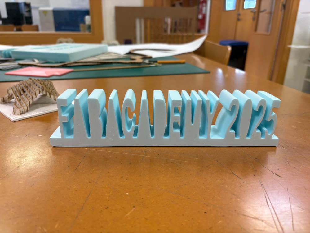
Then here is the result:
Documentation
- Rhinoceros: click here
- DXF: click here