week 16 System Integration
- Design and document the system integration for your final project
Design
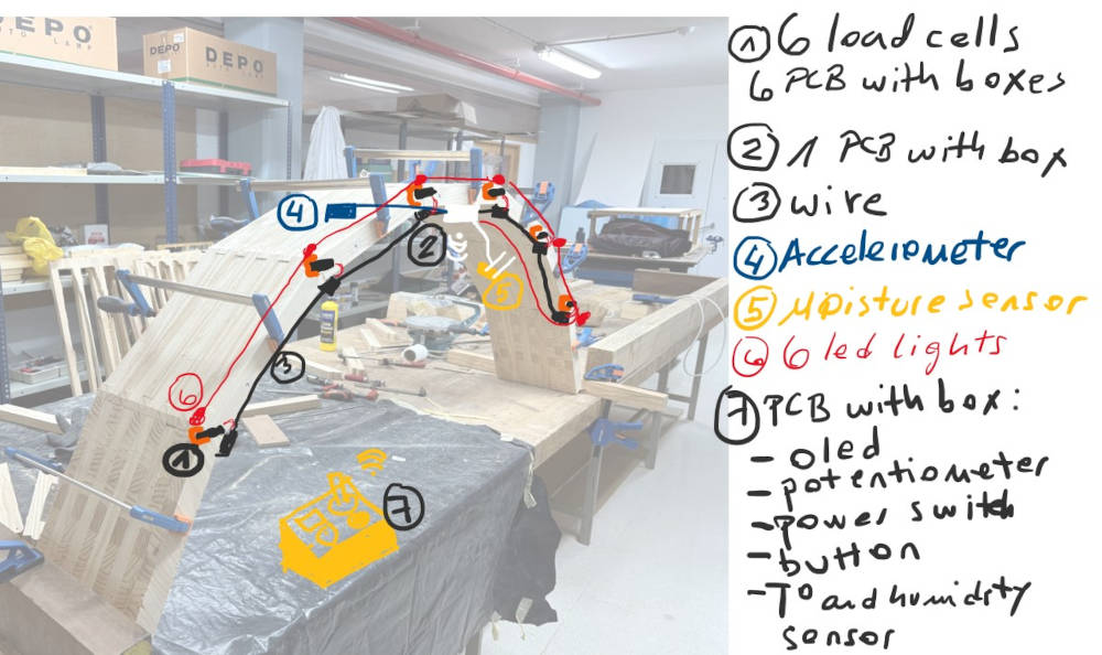
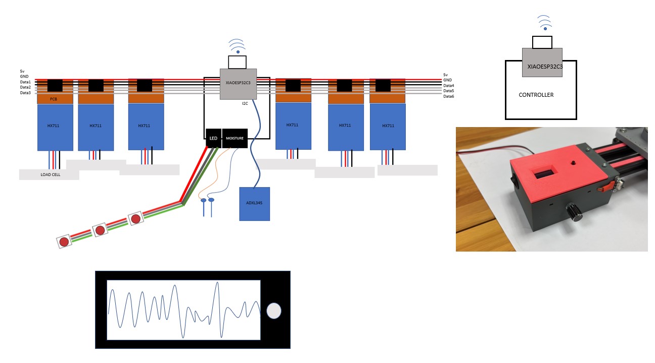
This week involved making important decisions about the project. The first step I took was to create a diagram illustrating the system integration of my project.
At first, I wasn’t sure how I was going to integrate all the components.
PCB
Since I hadn’t yet designed the PCBs, that was the first thing I tackled. You can find the detailed PCB design on the final project page.
PCB 1
This PCB serves as the central hub for data acquisition and communication within the system. It collects real-time data from multiple sensors, ensuring accurate monitoring of environmental and operational conditions. The gathered data is then transmitted wirelessly to a remote server, where it can be accessed and visualized through a mobile phone or tablet, providing an intuitive and user-friendly interface. Additionally, the PCB establishes a Wi-Fi connection with the control unit, enabling seamless integration and responsive interaction between sensing, data processing, and actuation components.
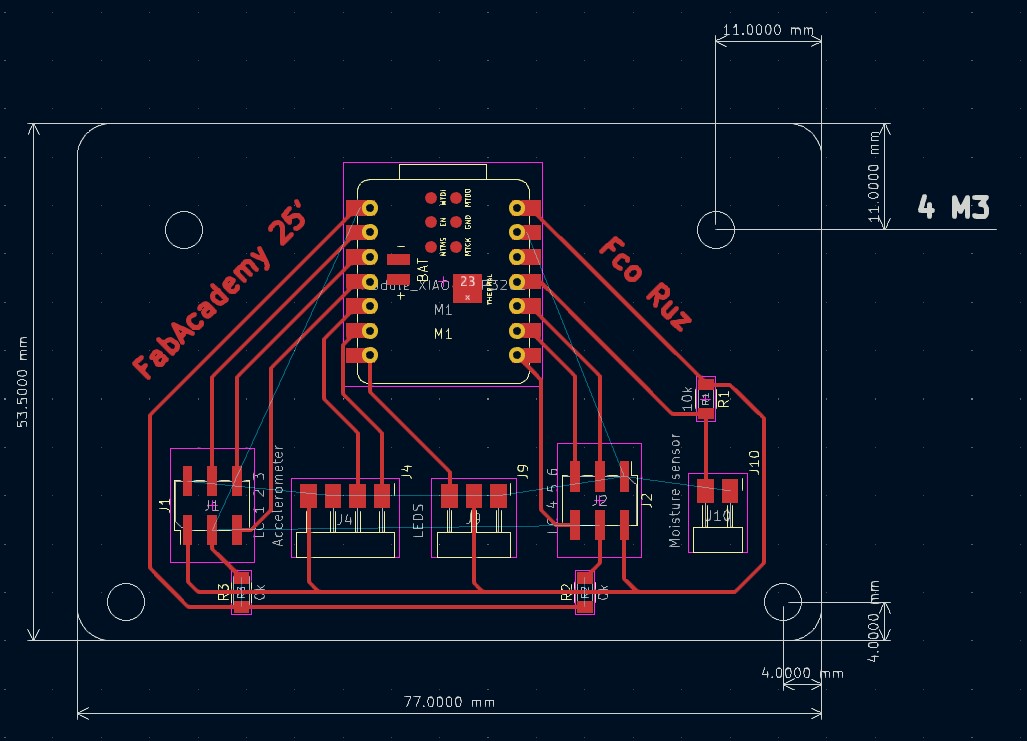
BOM:
| Nº | References | Value | Footprint | Quantity |
|---|---|---|---|---|
| 1 | R2, R3 | 0k | R_1206 | 2 |
| 2 | R1 | 10k | R_1206 | 1 |
| 3 | M1 | Module_XIAO-ESP32C3 | SeeedStudio_XIAO_ESP32C3 | 1 |
| 4 | J1 | LC 1 2 3 | PinHeader_02x03_P2.54mm_Vertical_SMD | 1 |
| 5 | J2 | LC 4 5 6 | PinHeader_02x03_P2.54mm_Vertical_SMD | 1 |
| 6 | J4 | Accelerometer | PinHeader_01x04_P2.54mm_Horizontal_SMD | 1 |
| 7 | J9 | LEDS | PinHeader_01x03_P2.54mm_Horizontal_SMD | 1 |
| 8 | J10 | Moisture sensor | PinHeader_01x02_P2.54mm_Horizontal_SMD | 1 |
This PCB acts as a bridge between the HX711 and the rest of the system. It ensures a secure and stable connection for the load cells, helping maintain data accuracy. Each load cell will have its own dedicated PCB, making the system more organized, easier to manage, and reducing the risk of interference.
PCB for load cells
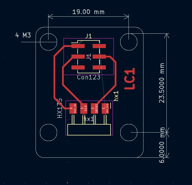
BOM:
| N° | References | Value | Footprint | Quantity |
|---|---|---|---|---|
| 1 | hx1 | HX135 | PinHeader_01x04_P2.54mm_Horizontal_SMD | 1 |
| 2 | J1 | Con123 | PinHeader_02x03_P2.54mm_Vertical_SMD | 1 |
Once I had the dimensions, I began designing their packaging.
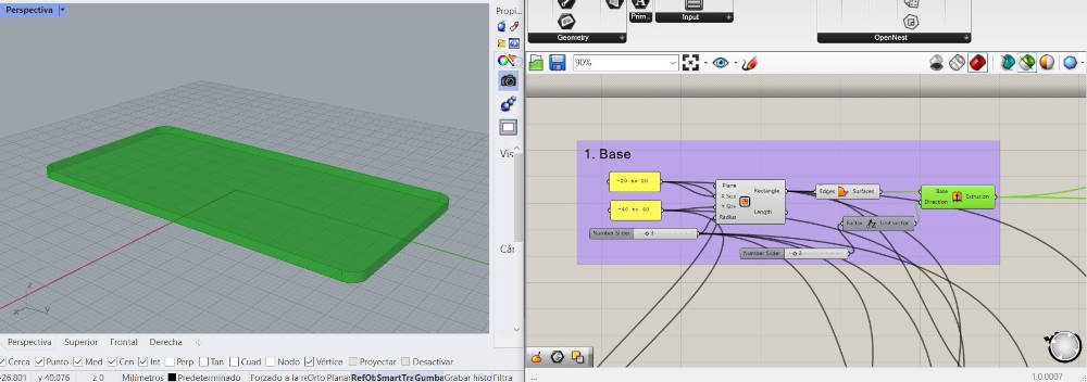
Packaging
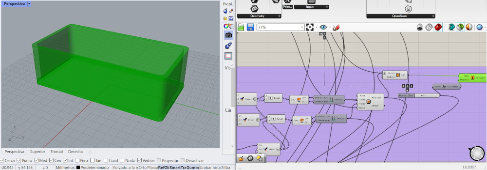
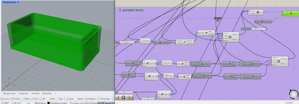
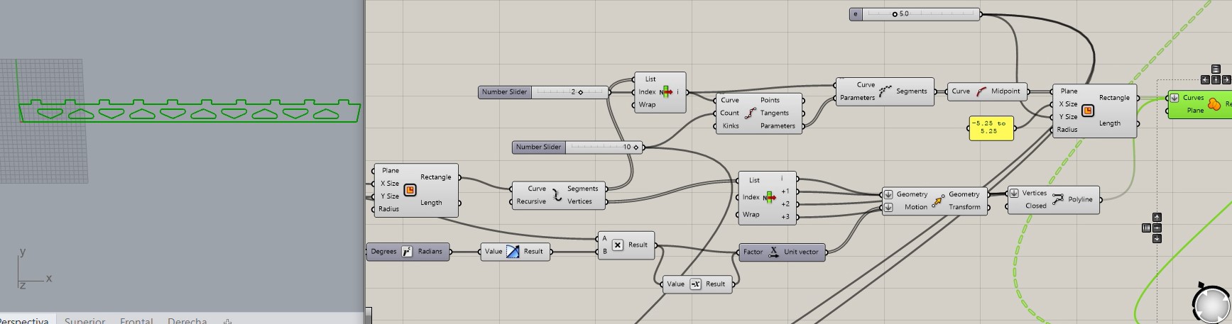
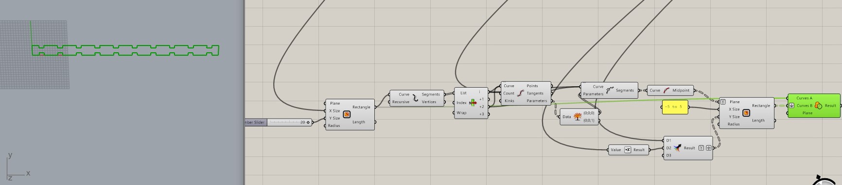
For the packaging, I used the same base box design for all components. Since the PCBs and sensors vary in size, I used Grasshopper to adapt the design accordingly.
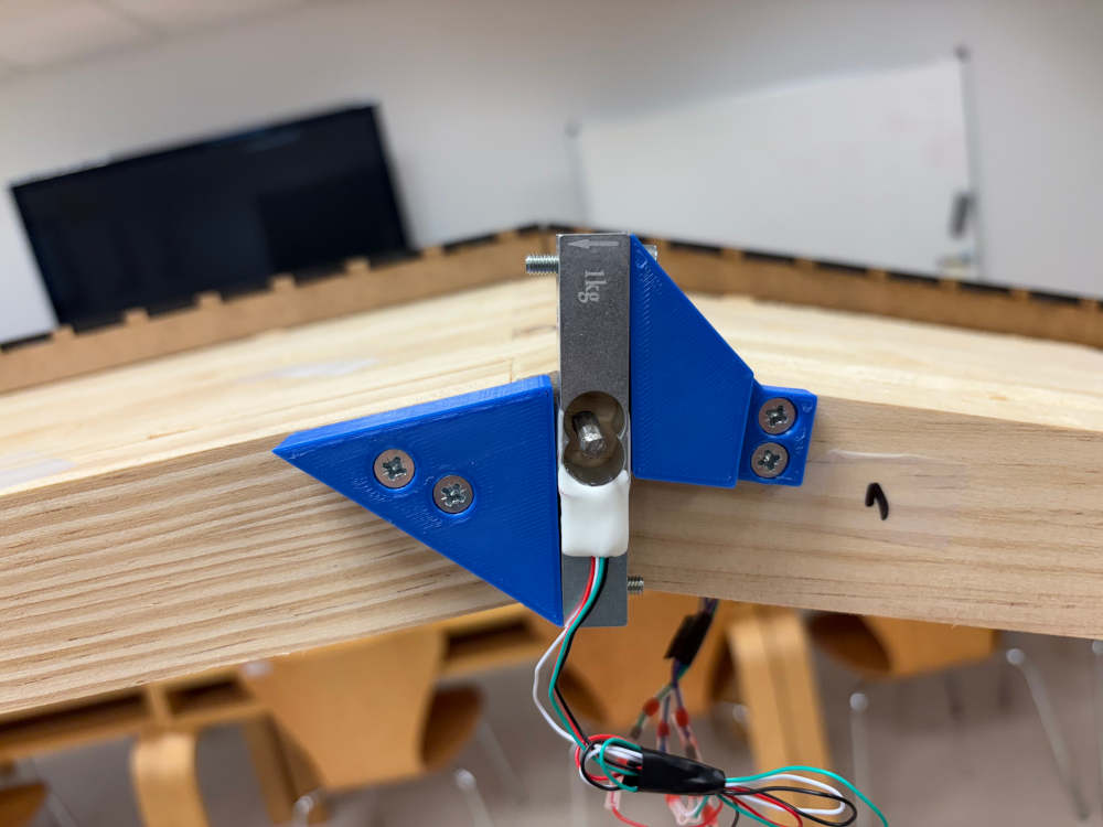
Load cells
For the load cells, I created the following diagram:
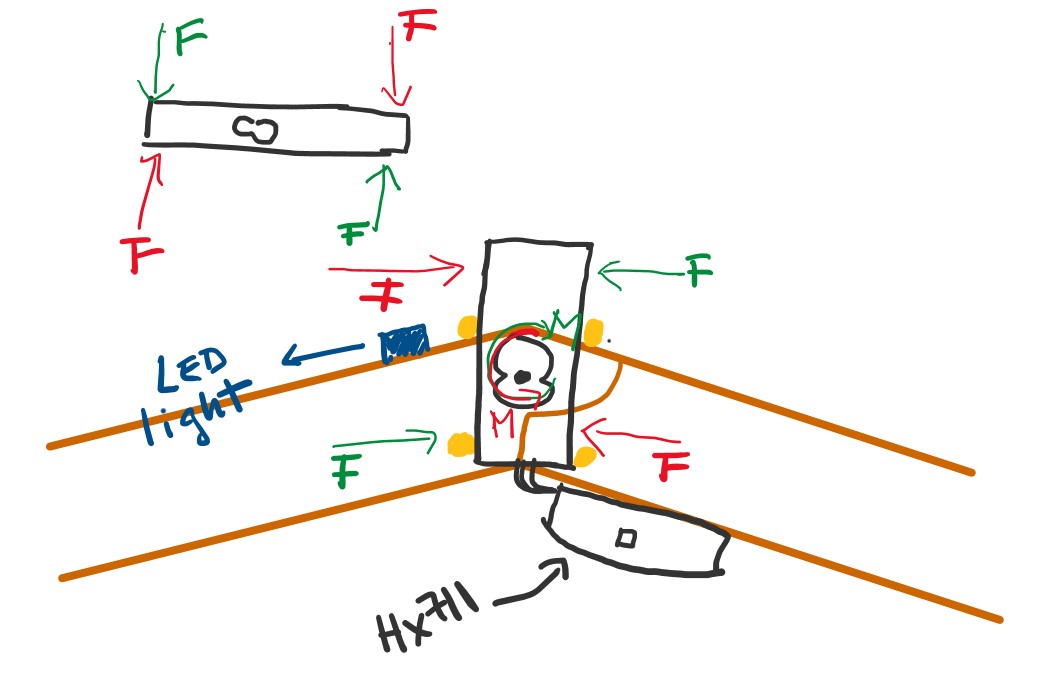
The purpose of the load cell is to detect any moment or rotational force at a joint. If such a force is detected, it could indicate the presence of a hinge, potentially leading to a local or even global structural failure. To ensure accurate readings, 3D-printed components will be used to apply a counterforce to the load cell, as it operates by sensing bending forces.
Moisture Sensor
This moisture sensor uses two metal nails inserted into a piece of wood, creating a basic resistive sensor. It measures electrical conductivity, which changes with the wood’s moisture content. One nail connects to ground, and the other to a voltage divider made with a 10kΩ resistor and the 5V supply. The midpoint of the divider is read by an ADC pin on the Xiao ESP32C3 microcontroller. As the wood’s moisture level changes, so does its resistance, altering the voltage and allowing the system to estimate moisture content.
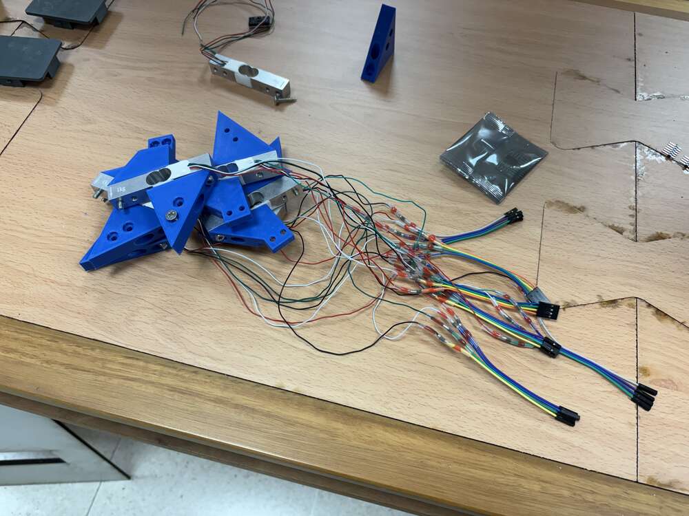
Wiring
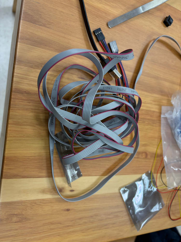
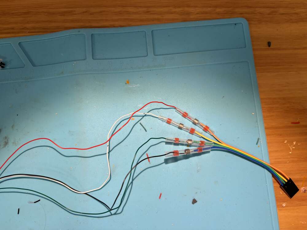
For the wiring, I’ll use a ribbon cable 8257523.
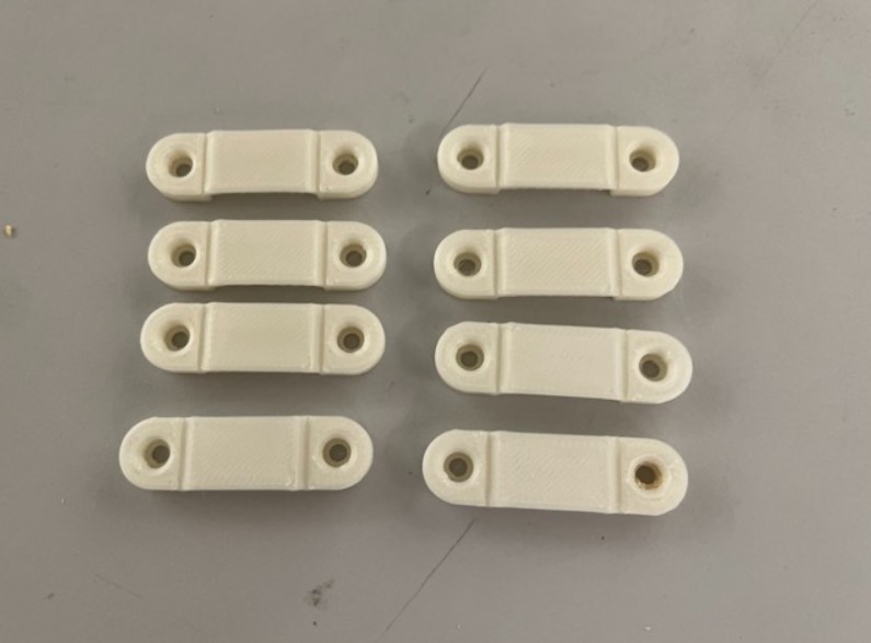
To attach the cables to the bridge, I’ll use a wire mount developed by Angelina Yang
Data visualization
To visualize the data, I will develop an interface that displays acceleration values, wood moisture, ambient humidity and temperature, as well as the readings from each load cell. A smartphone or tablet will connect to the ESP32 via Wi-Fi, allowing real-time access and interaction with the data.
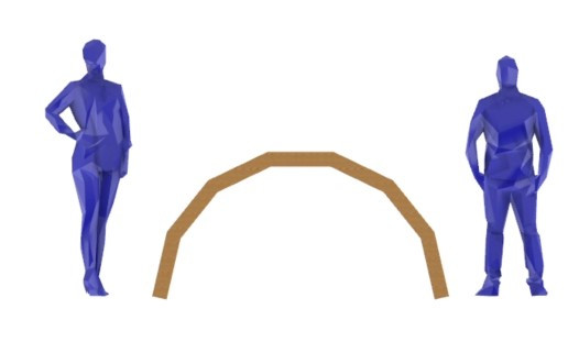
Final project
My final project will have the next aspect with a parametric design
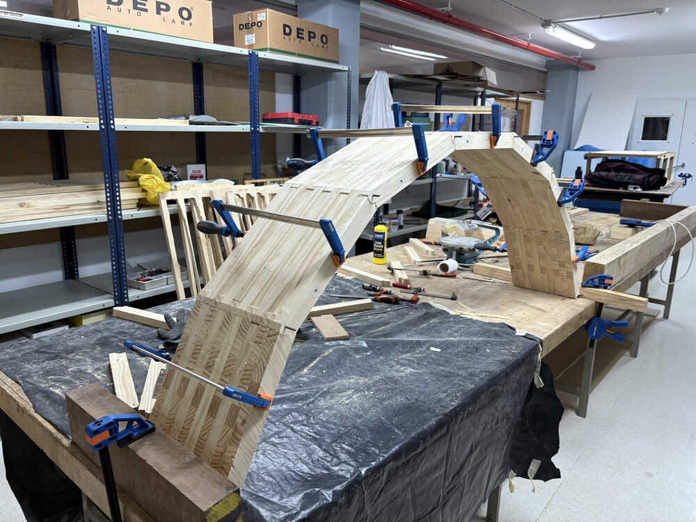
After constrcuted it look like this:
The electronic part follow the next diagram done on the middterm week:
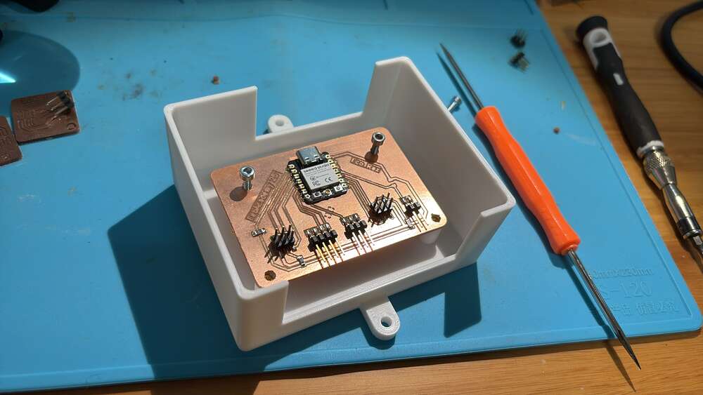
This week I did boxes to protect the electronics and that everything is on its position
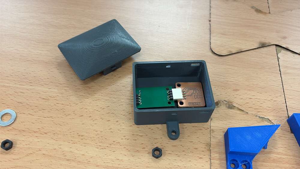
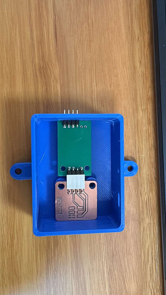
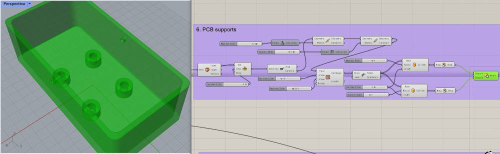
For the principal pcb I did a box with large holes so i dont have problems with wiring
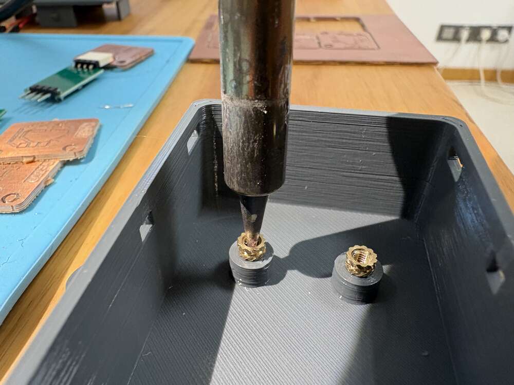
I used threaded inserts to add strong screw threads to my 3D printed part
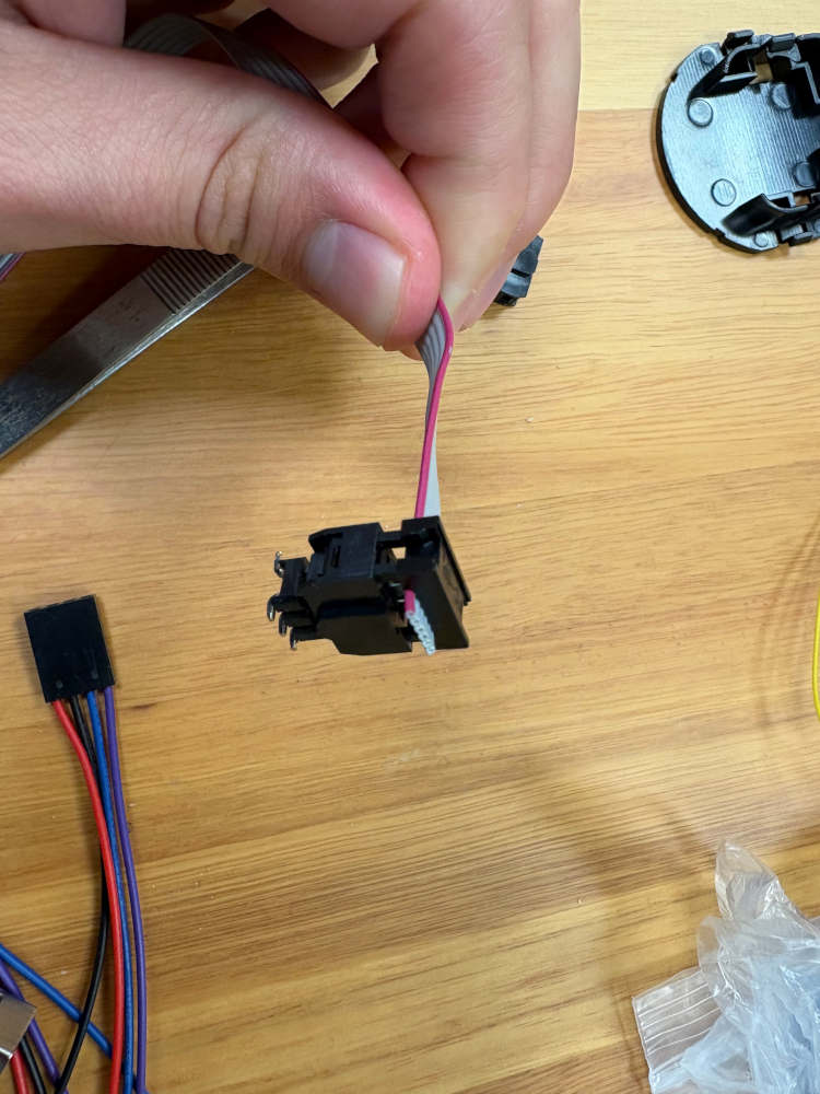
I used from ctronics a very nice connector that gives rigidity to the connection and it is very easy to solder.
Once it was ready I assembled with the structure.
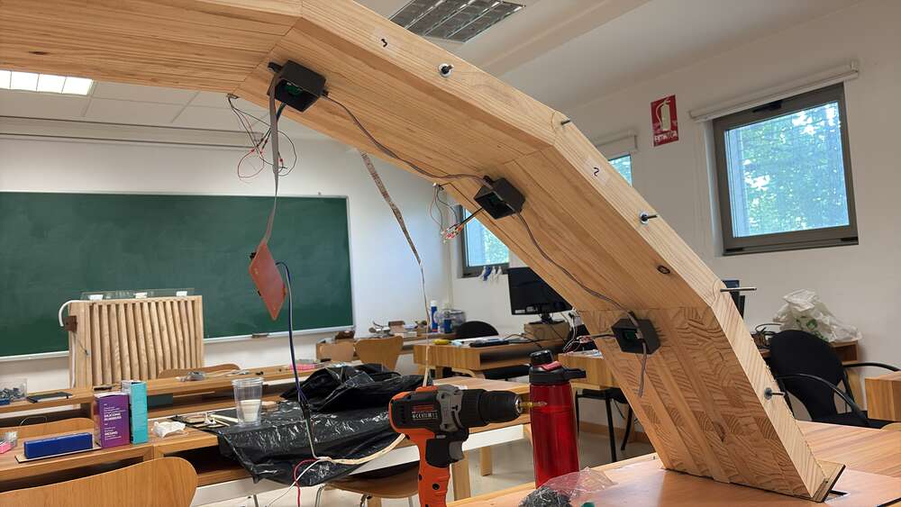
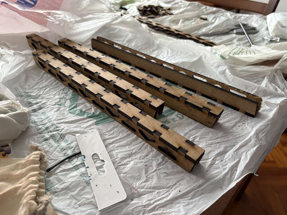
For the led lights with I combine wood worked on the laser machine and 3d print
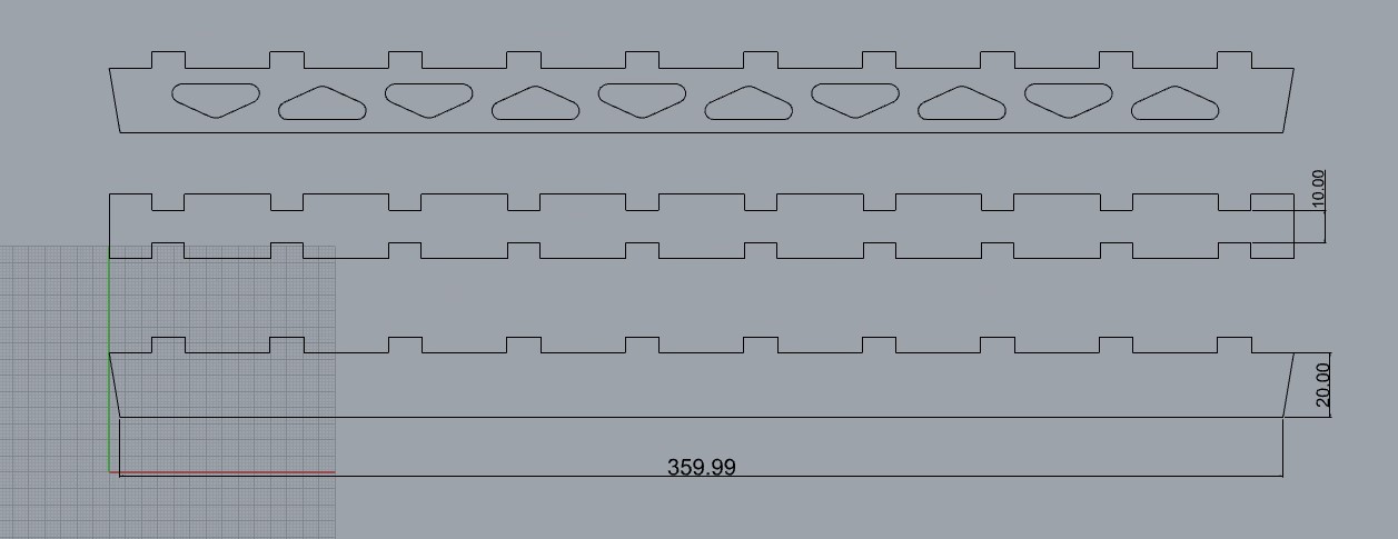
- Laser cutting
The box for the led light was done with the laser cutting machine, the design was primordial so this can work properly. The length was the same that the wodden parts so it fits with the arch curvature.
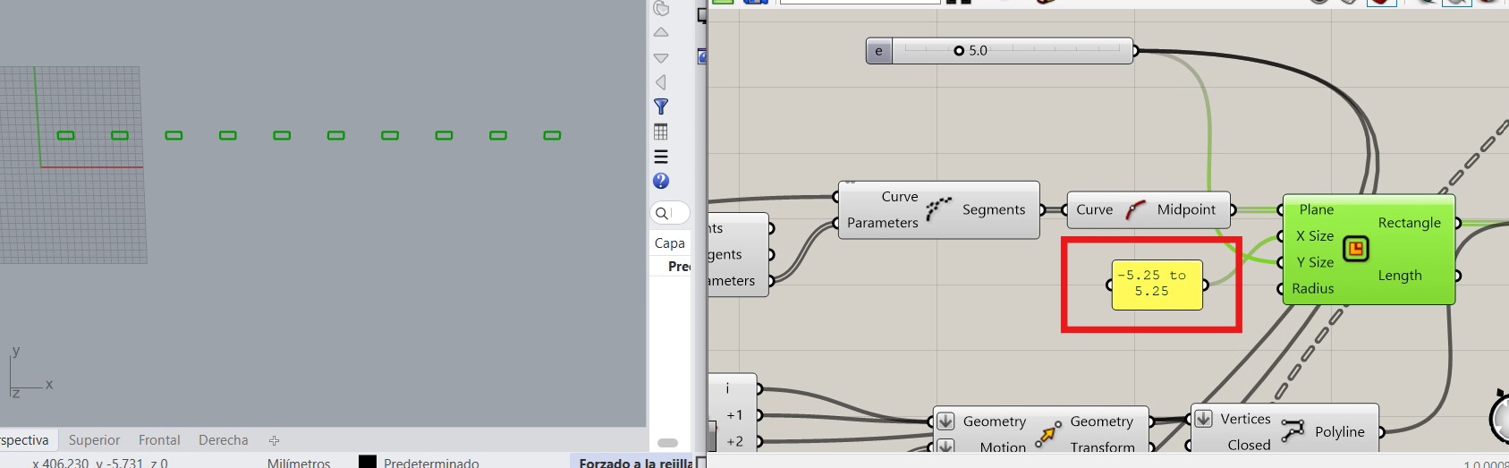
With this parameter I controlled the tolerance of the parts so they doesn’t move. However, I fixed them with glue
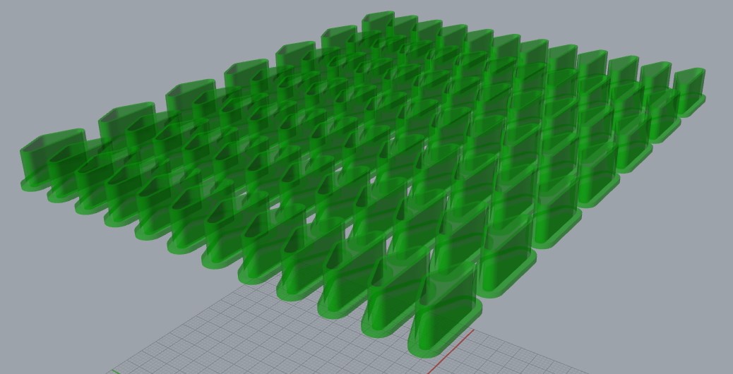
Finally, these are the 3 parts I cutt on the table 7 times
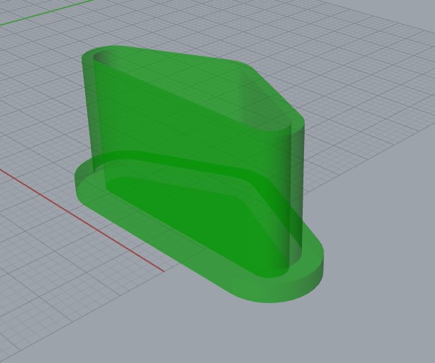
- Print The ideas of the led was that the strip is pressured by the 3d print so it does not move. First I did a square and trace a diagonal. then did a scale
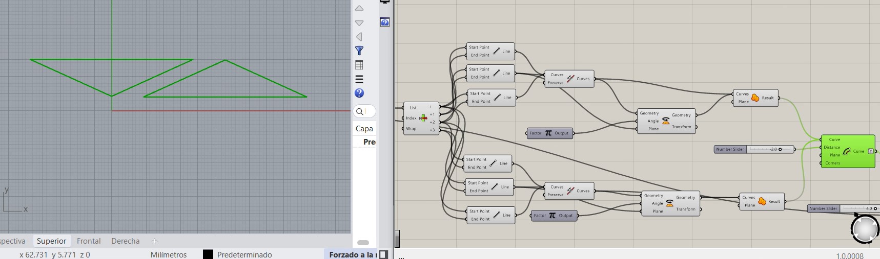
Finally I put fillets on the corners. It looks cool.
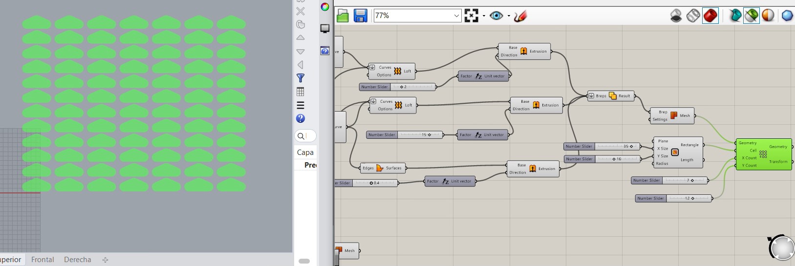
and these are the parts I printed on the 3d printing machine
Lastly, for the first support I did bascially a triangle and then fixed to the wodden part and the load cells.
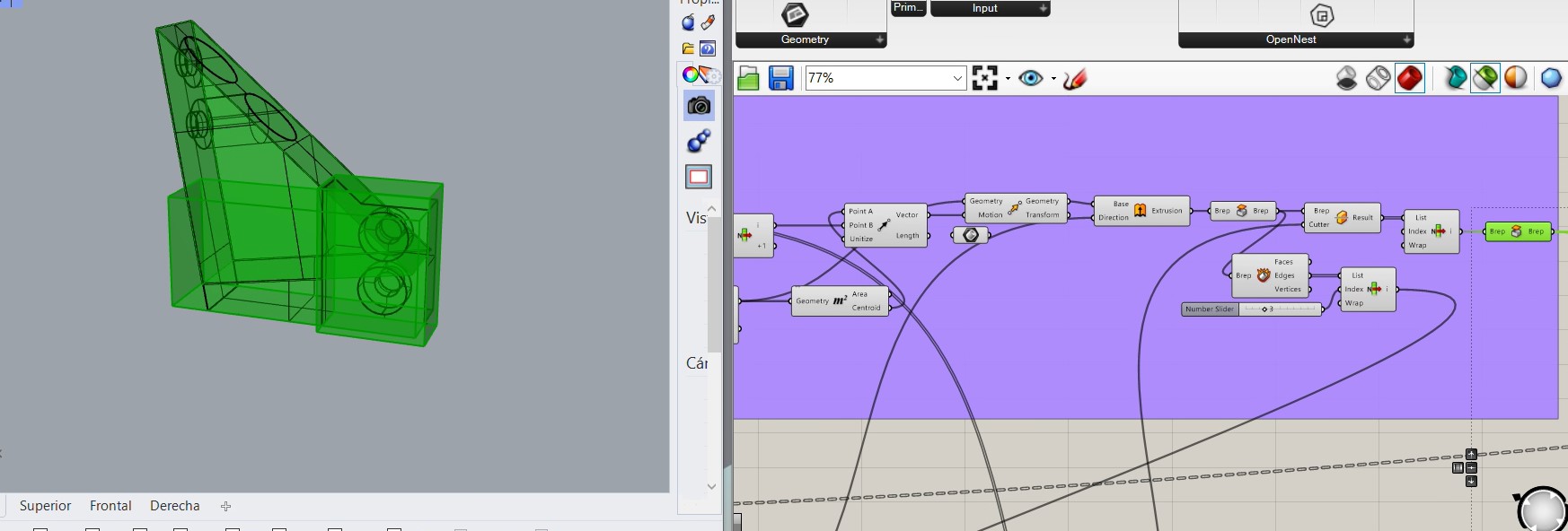
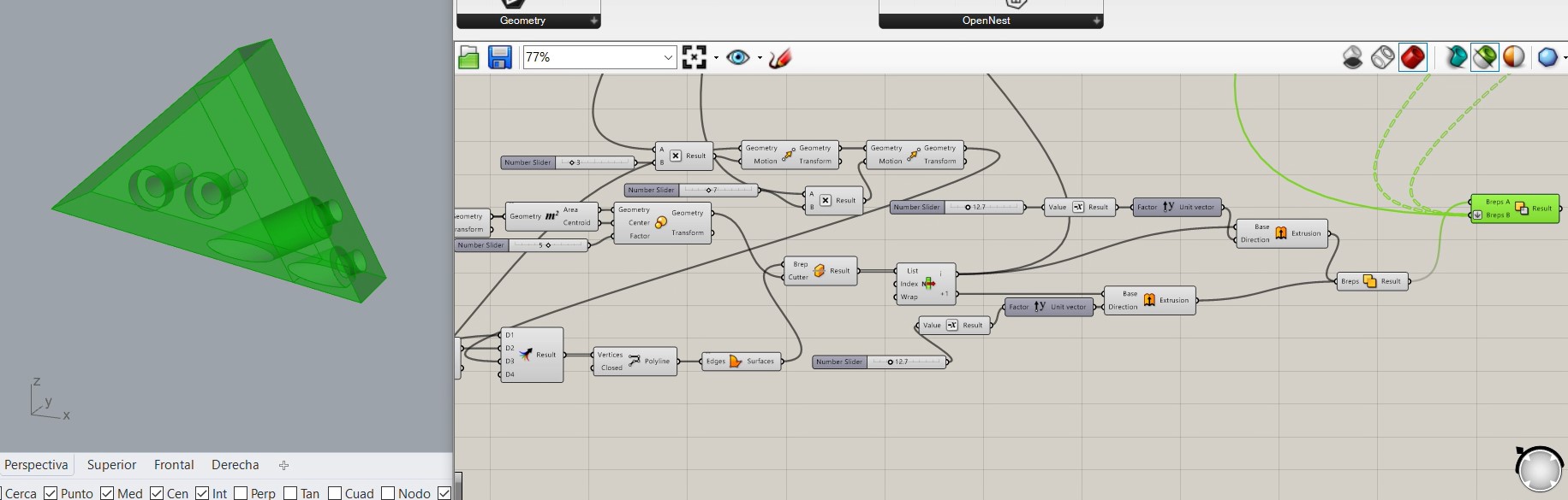
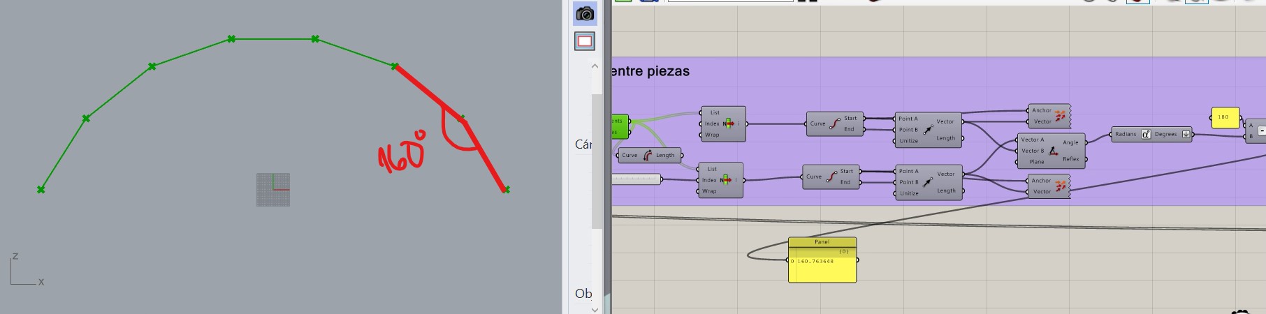
The second part is simpler because it is just a triangle, where I used the code of V3 and the middle point of the joints to do the rectangle that I used as reference.
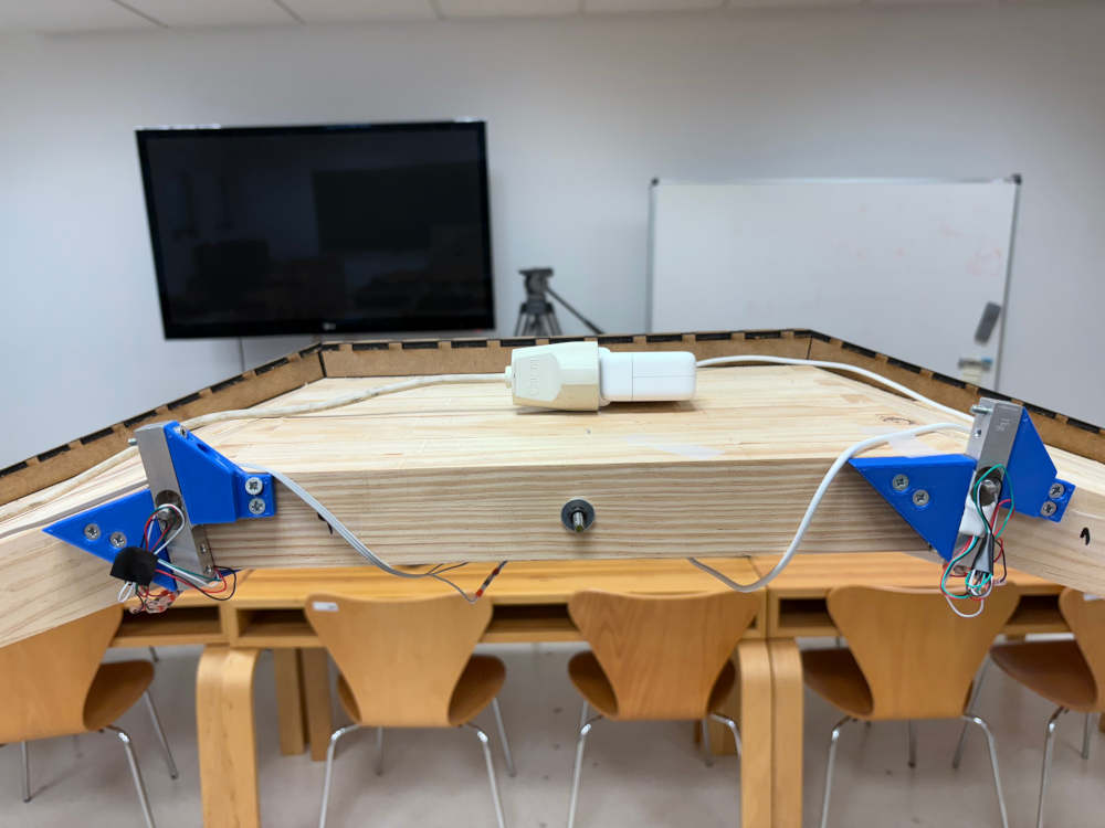
Finally these is how the parts are installed.
Inside the box
When it is already installed this is how it looks:
hx711 on the middle
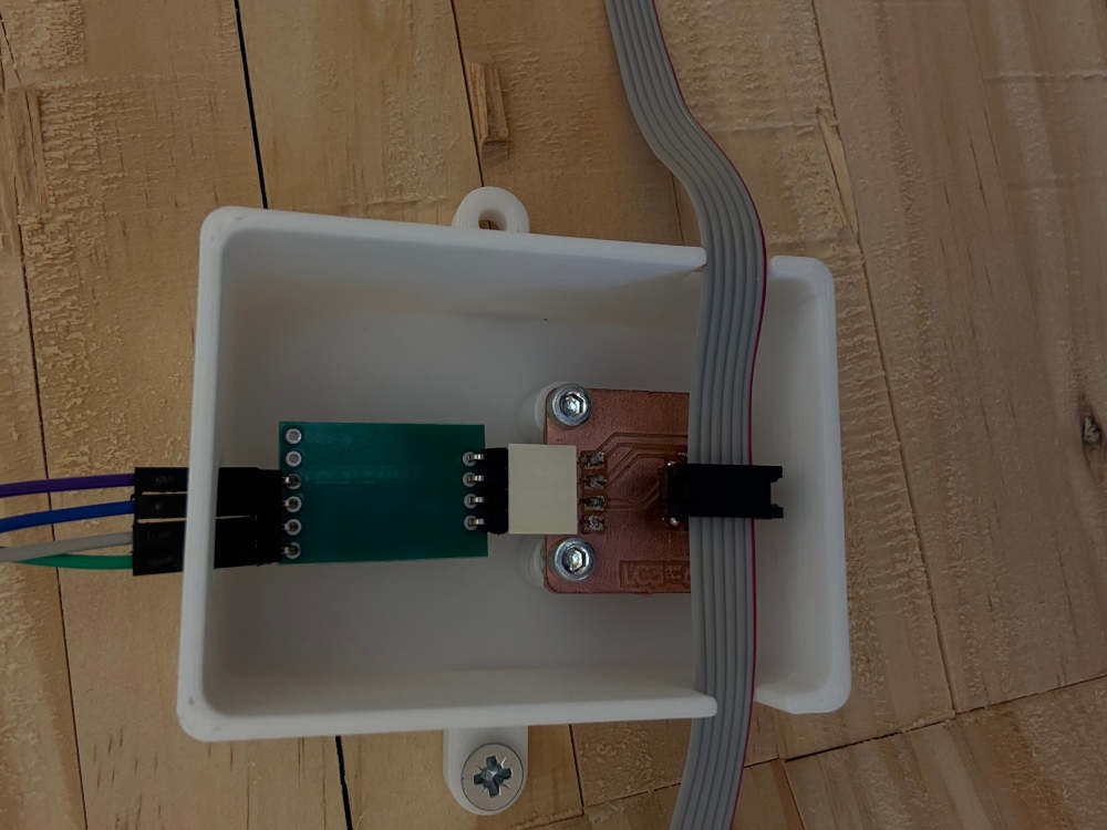
hx711 most far of the central hub
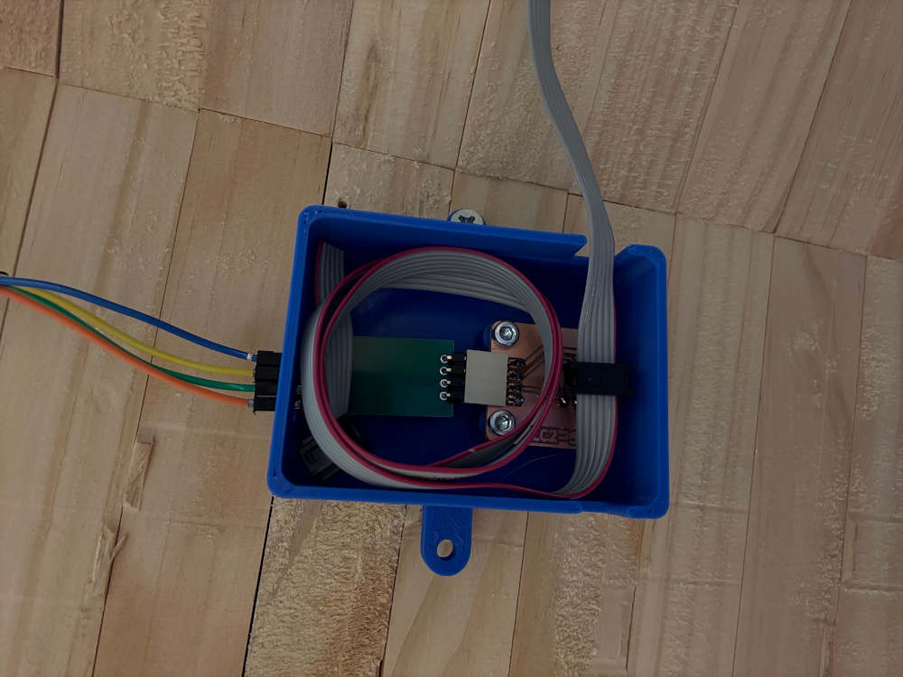
central hub:
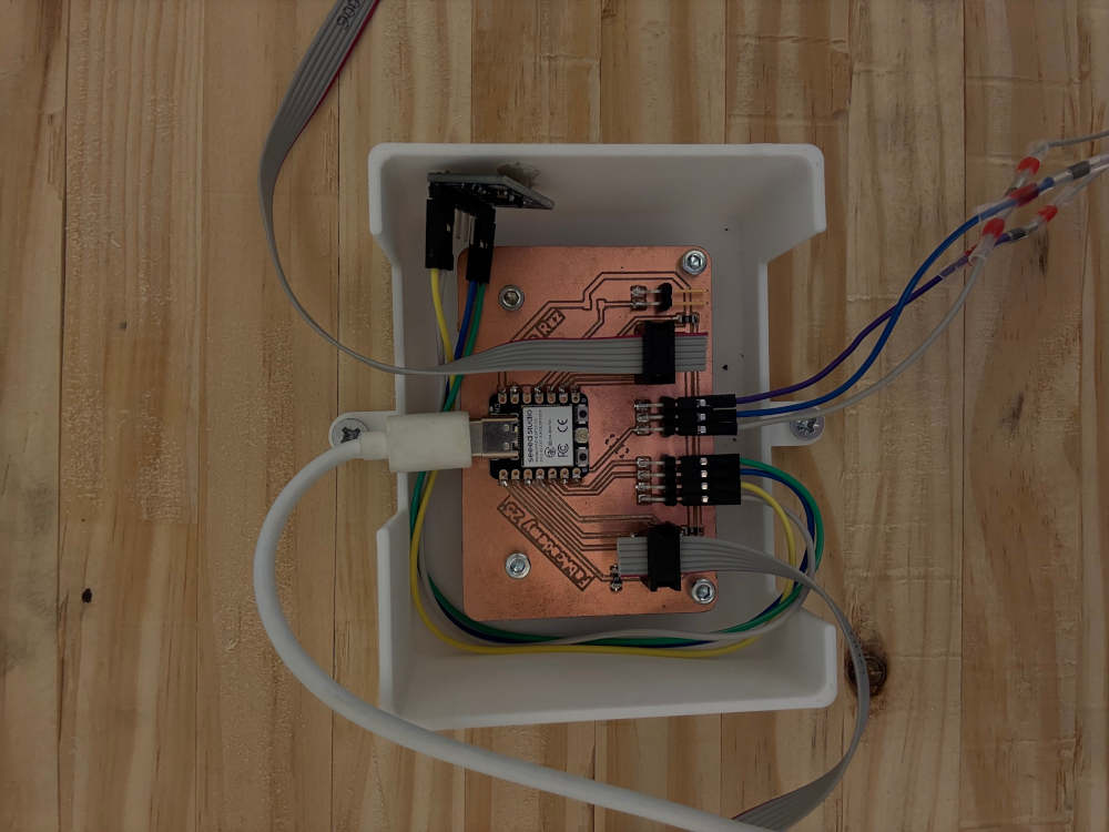
which is placed just in the middle of the arch above the woodden table that is on the highest point. like on the following image. Also in the image we can see the supply of the power to the central-hub is made with normal current
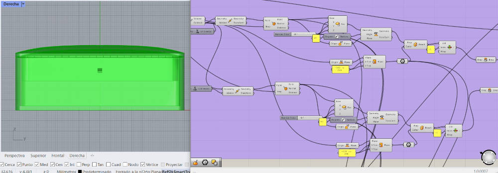
On the other hand, for the box the LED light to fit with the arch curvature I used the parametric design and the information it gave me
Finally this week I could not work on the fablab because it was closed during the weekend so I took things home and work on embedded programming.
This was the result:
- Accelerometer
- Load Cell
Documentation
- Grasshopper box: click here
- Grasshopper project: click here
- STL box: click here
- Leds: click here