Week 07. Computer Controlled Machining
Making a TV table
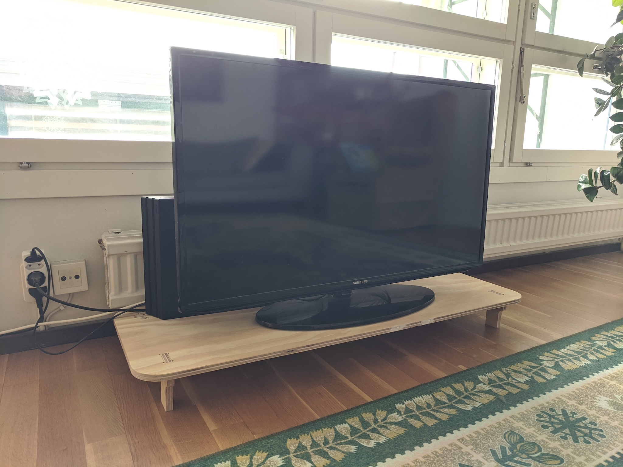
TV table in place, made with draft plywood.
Design
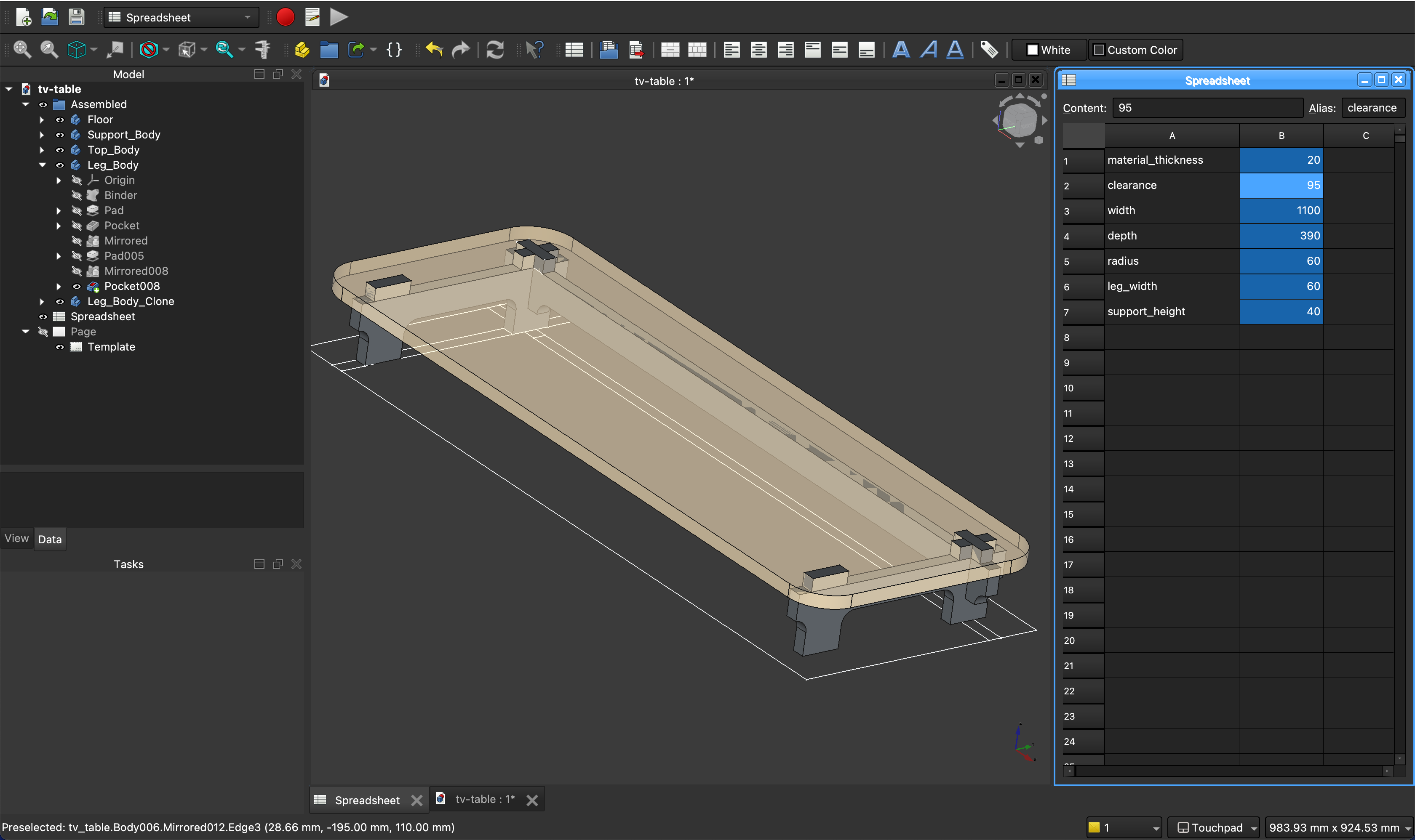
Parameters
| Name | Dimension |
|---|---|
| material_thickness | 20 |
| clearance | 90 |
| width | 1100 |
| depth | 390 |
| radius | 60 |
| support_height | =material_thickness * 2 |
| leg_width | =material_thickness * 3 |
The dimensions are based on how we use the space. The goal was to get the TV, wires, and game console off of the floor. It should have enough clearance to allow vacuuming under it. It shouldn't be much higher than that, because we don't want to block the window.
FreeCAD
Getting used to parametric and constraint-based modelling in FreeCAD is taking some time. There are dragons. At one point I had a design that I thought was fully parametric and contrained, but changing the material thickness broke everything. Tips:
- If a sketch loses its attachment reference when changing parameters, step through the previous steps to see where the sketch should be attached, then chose "attachment editor" on the sketch to reattach it.
- "Dress-up features" like fillets can be more stable if modeled as pads and pockets.
- Distance constraints from an edge can swap sides if not careful.
I'd like it be easier to test multiple versions of a design during design time. Is it possible to make a "component" part that includes parameters, that can be used as multiple instances with different parameters? Having this kind of setup might make issues visible at design time.
Wood deflection calculation
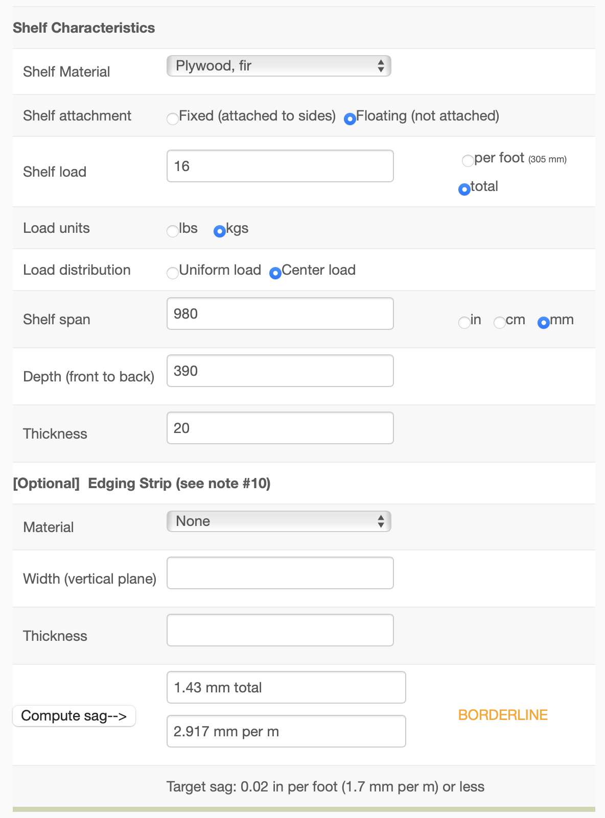
I found an online calculator for wood deflection ("Sagulator") to check if my material would noticably sag without support. The result was "borderline" so I kept the cross support in my design.
3D views
As part of the design flow, I exported GLB from FreeCAD and converted to USDZ with Apple's Reality Converter utility.
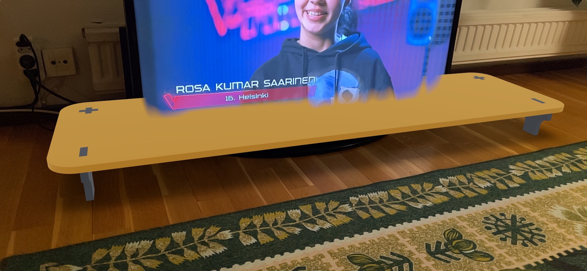
USDZ files can be sent directly to iPhones, and viewed natively. I sent a few versions to my partner with this flow, and they could rotate the model with touch gestures, and view the table in place with augmented reality.
2D views

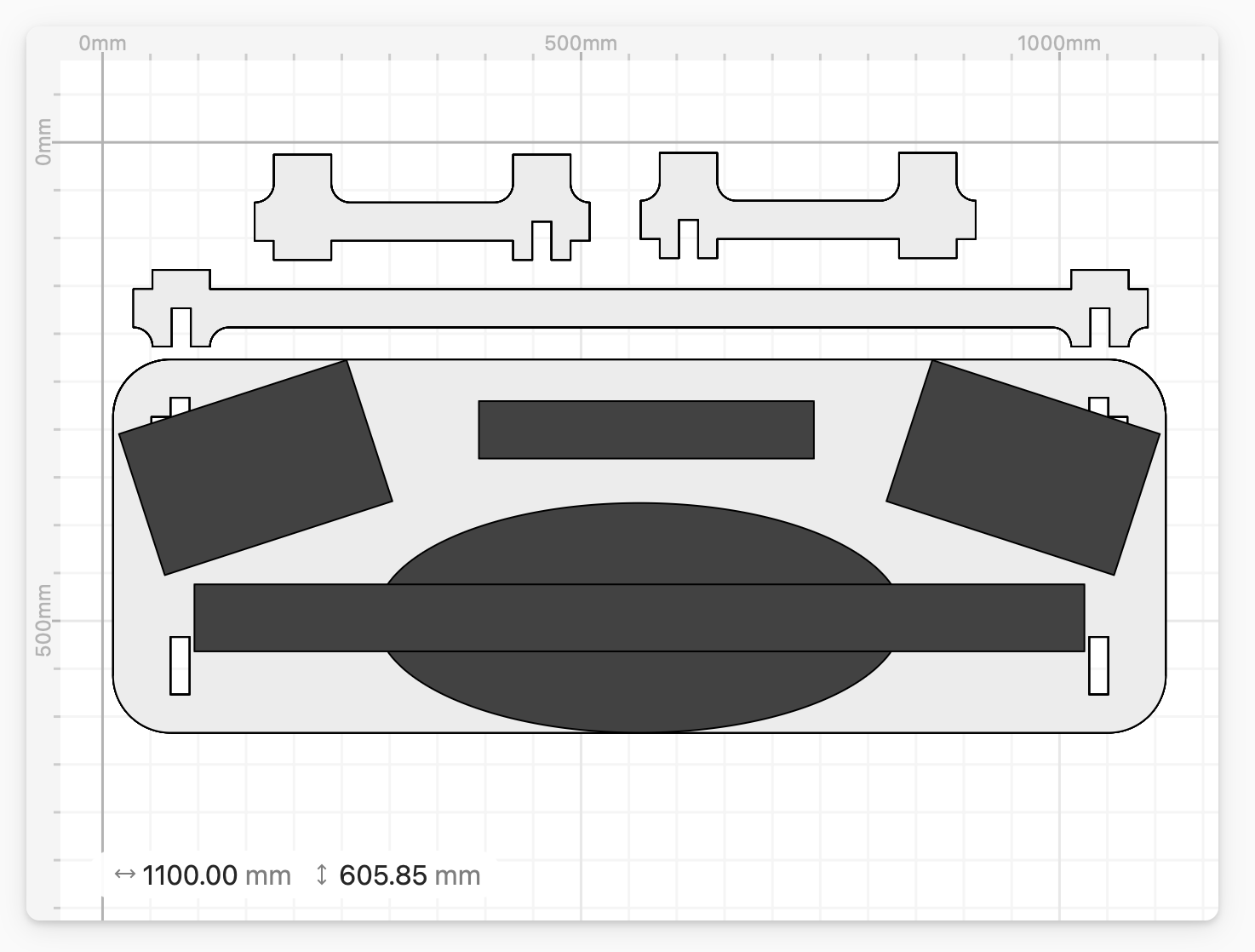
FreeCAD "TechDraw" view of the cut layout. This is a good way to get the parts out as vectors to import into VCarve.

Here is how to put the table together. These views are also added to a TechDraw page, by selecting the desired parts from the assembled group in three steps.
Prototype cuts

I imported the cut shapes to Cuttle to do a quick scaling. The scale adjusts to the material thickness, so the relative size of the joints don't change.
With the real-scale version, I also mocked up how speakers and game console would fit behind the TV. This validated the planned width and depth.
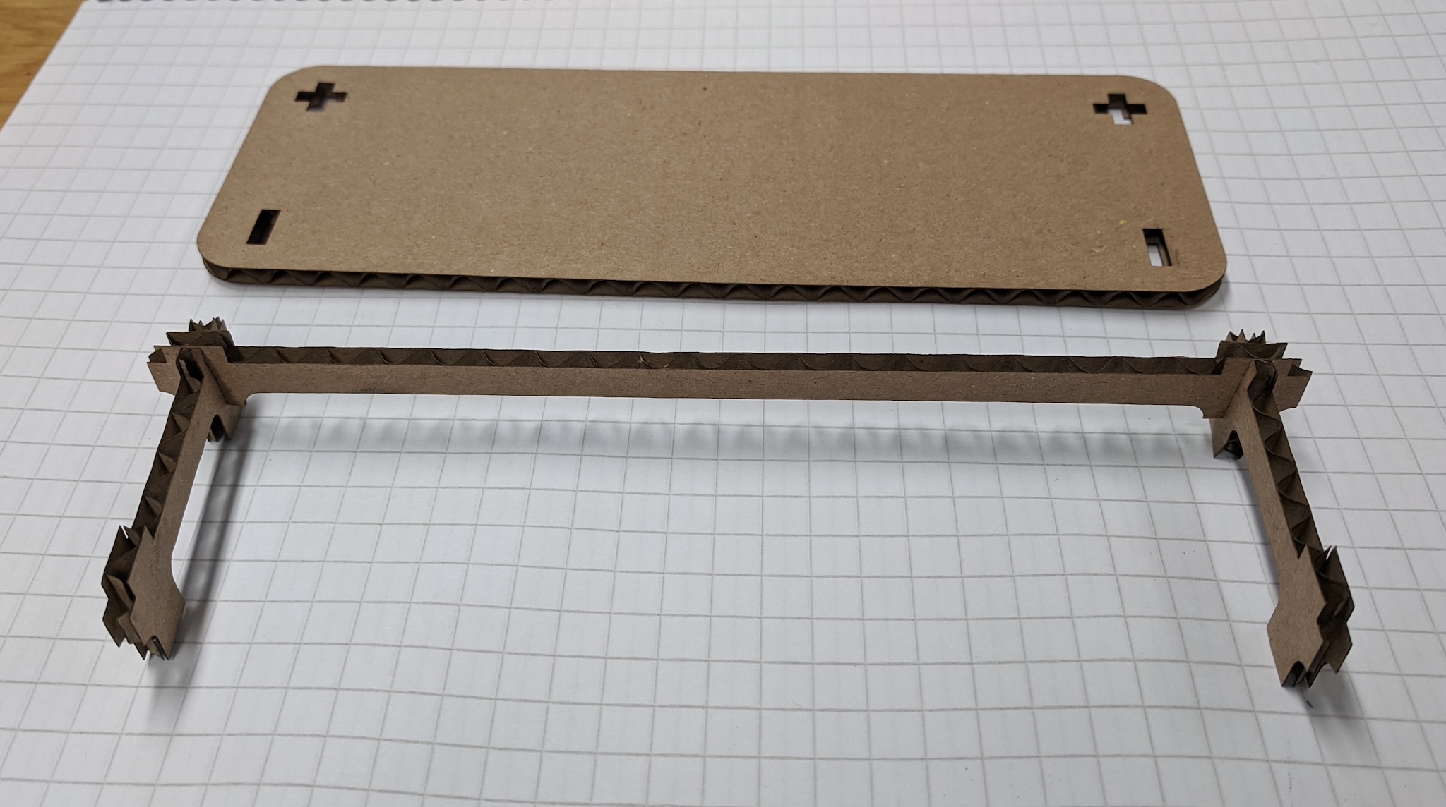
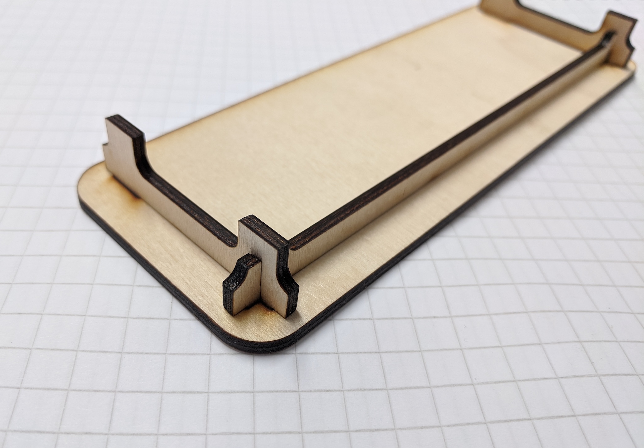
3.2mm corrugated card test cut. How the legs and cross support slot together.
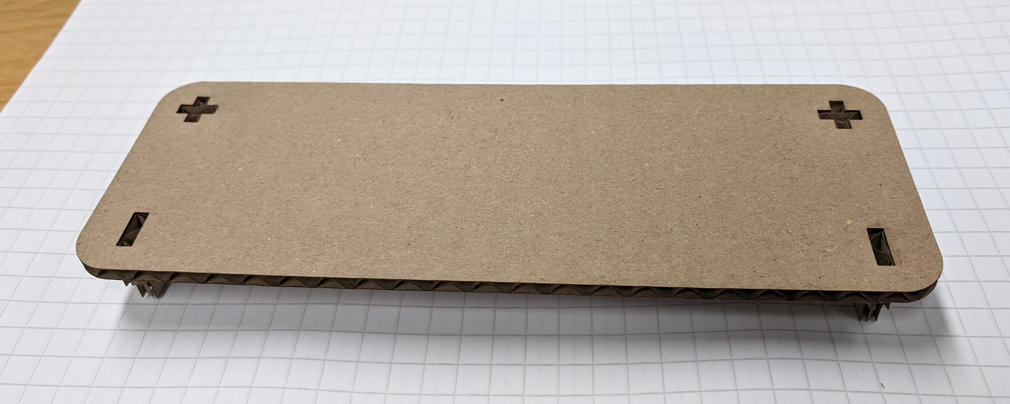
The tabletop sits on the legs, and does not need glue or fasteners.
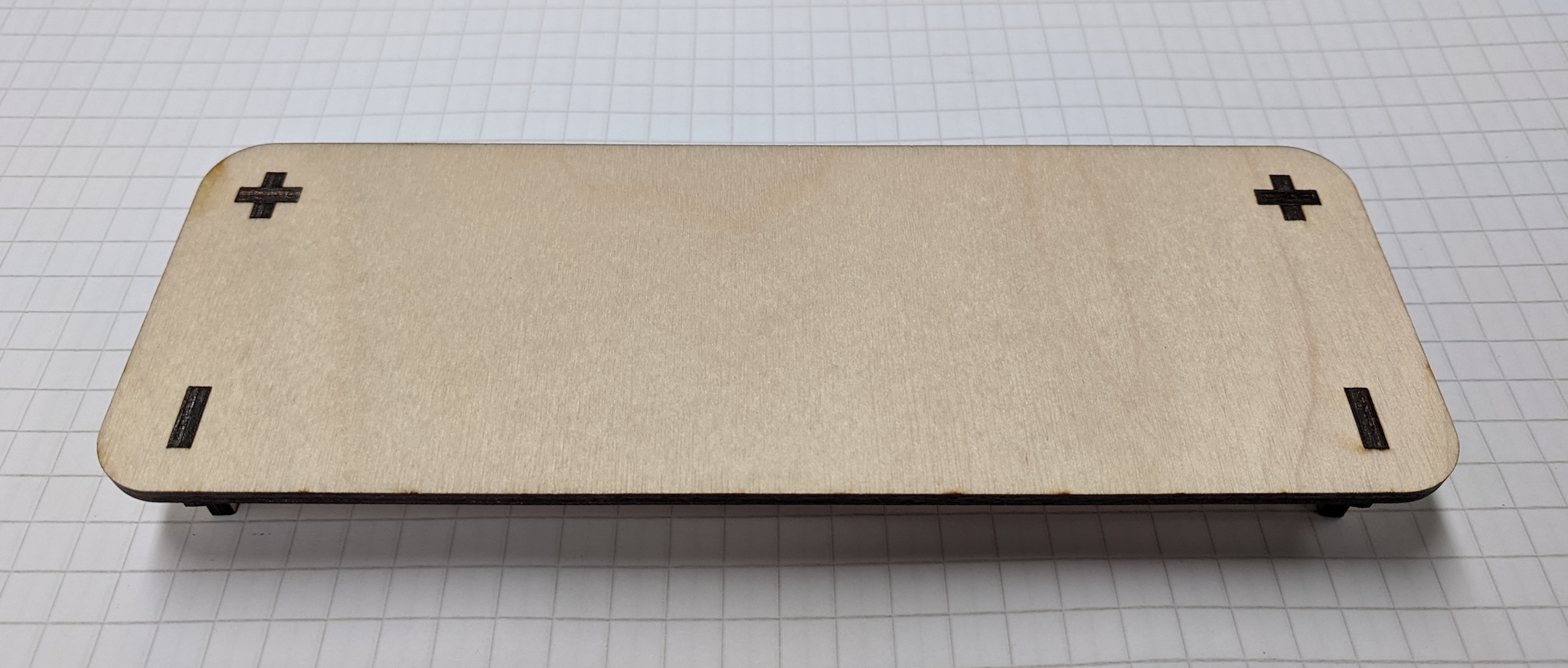
3mm plywood test cut, which is 3:20 scale. For fun. I like the idea of keeping miniatures of furniture with the actual furniture.
This makes me wonder how small I could go. 300gsm cardstock is about 0.3mm, so that would be 1:10 of this one.
View of the small plywood joinery from under the table.
15mm test plywood cut.
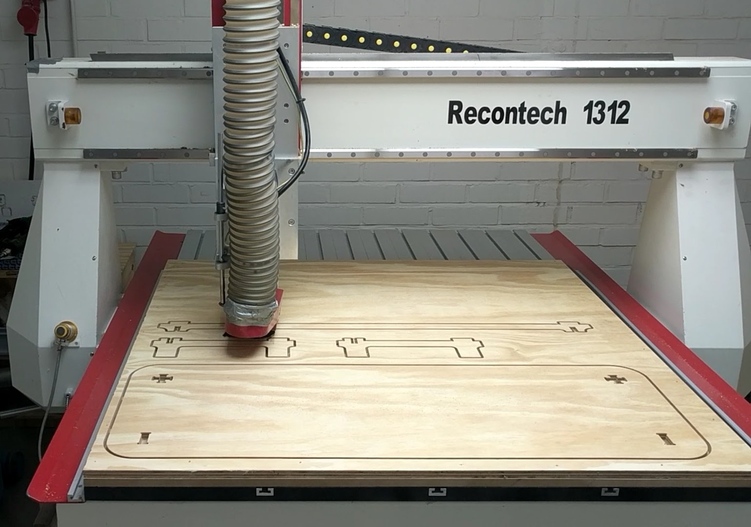
- Machine: Recontech 1312
- CAM: vCarve to make the gcode that was sent to the machine.
- Dogbones were added in vCarve.
- Tool: Sorotec 6mm 2-flute straight-flute cutter
The original plan was to do a second cut with nice 20mm Baltic birch plywood. But I decided to use this version for a while. I did a quick sanding pass, and took it home on the metro.
In situ
Nice.
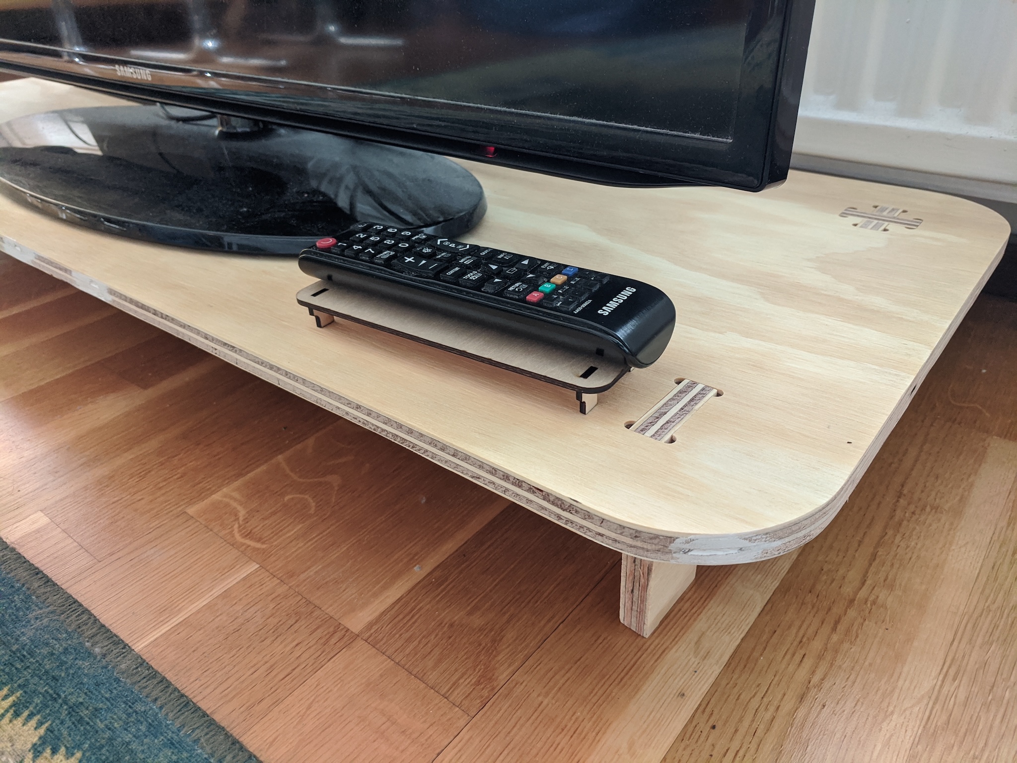
The prototype miniature as table for remote.
Frank's maiden voyage. 🫠
I didn't account for the rug in the original parameters, and anyhow the tolerance is too tight for the vacuum cleaner. So I'm glad that I decided to use this test version before doing the final.
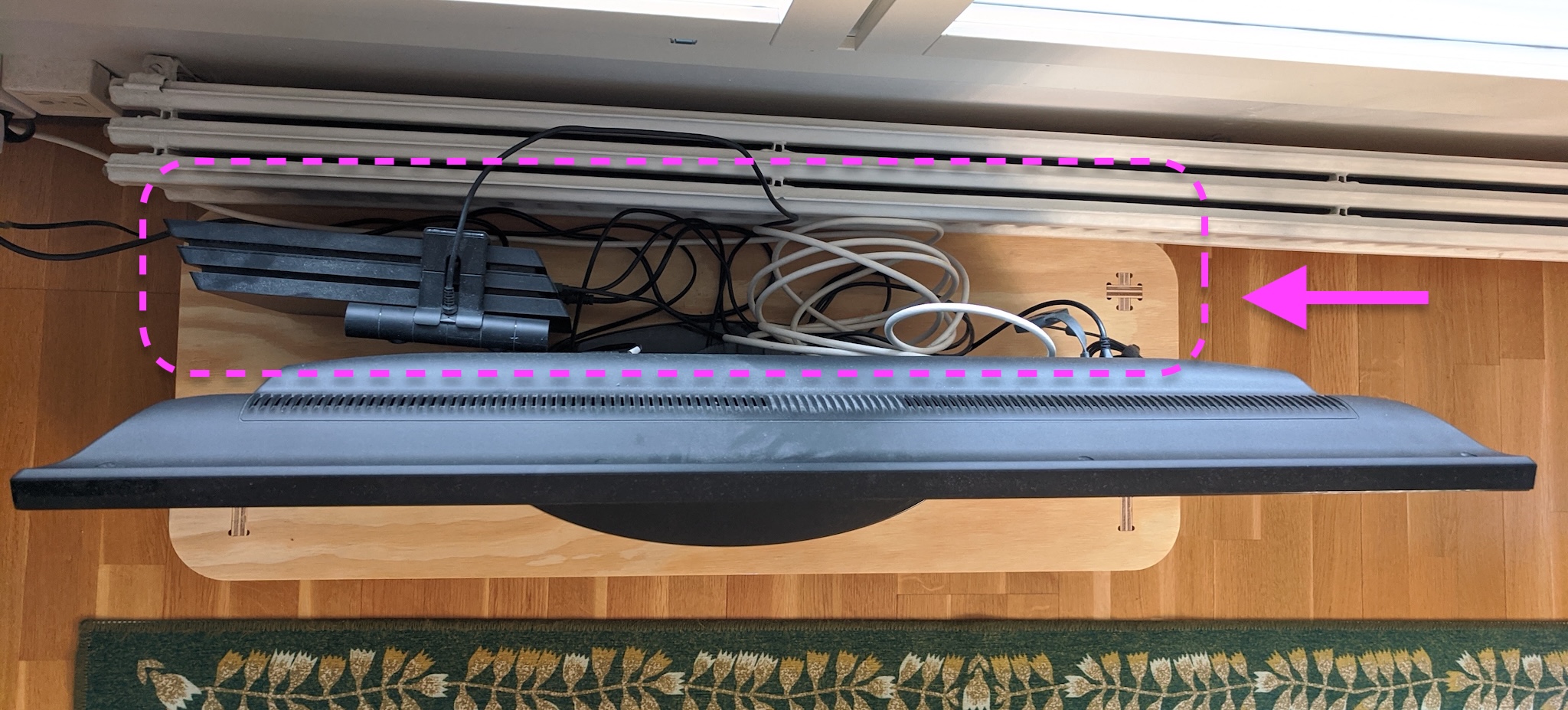
My initial sketches included shelving behind the TV to organize this stuff, which could be a part of the next version.
Project files
- FreeCAD: forrest-tv-table.FCStd
- Cuttle project
Group work
Material fastening
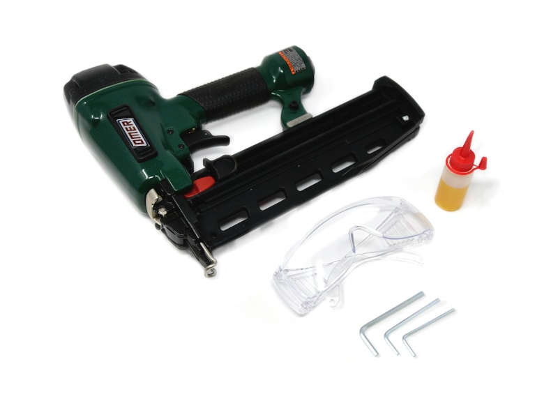
We have a pneumatic composite nailer, which is nice in combination with the vacuum table.
The vacuum holds the spoil board, and the nailer fastens the material to the spoil board.
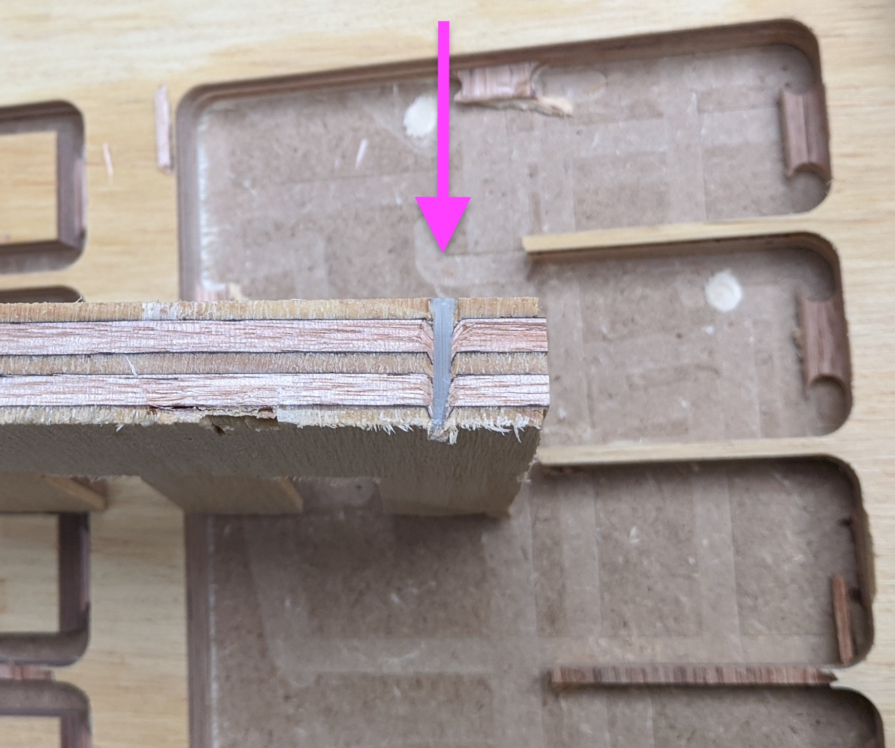
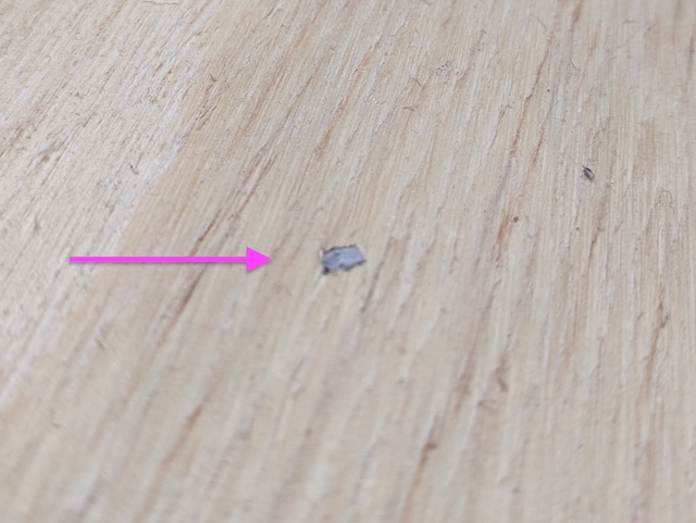
The cross section of a fastener that was directly hit by the milling tool.
If the tool hits a composite nail, it does not damage to tool. The toughness of these fasteners is similar to the wood that the milling tool is made to cut.
Test comb
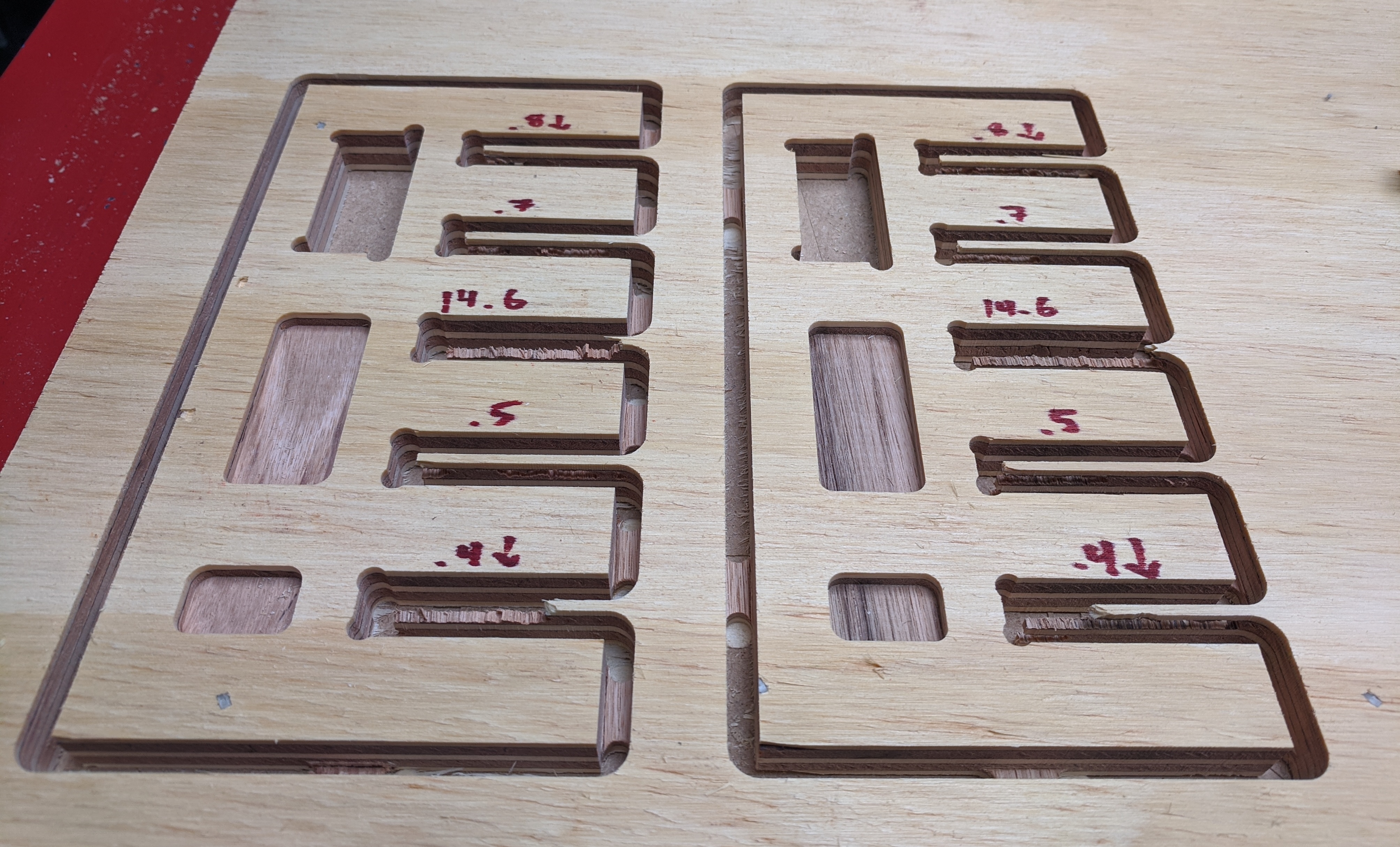
Designed this fit test comb in VCarve to test 0.1mm increments to see haw tight slots should be. 14.6mm is the material thickness of the draft plywood.
Running a job
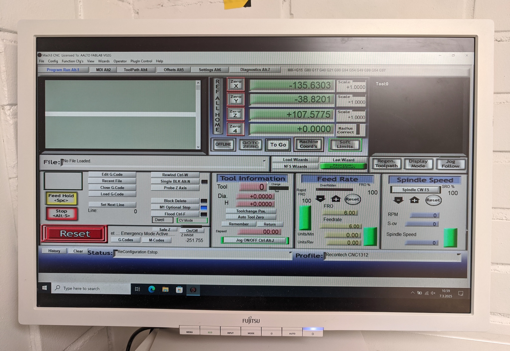
Just look at this beautiful interface.
- ← Previous
Week 06. Electronics Design - Next →
Week 08. Electronics Production