Week 3
Computer-Controlled Cutting
Organizing
checklist
| group assignments | — |
|---|---|
| Characterize your lasercutter’s focus, power, speed, rate, kerf, joint clearance and types. | |
| Document your work to the group work page and reflect on your individual page what you learned. |
| Individual assignments | — |
|---|---|
| Design, lasercut, and document a parametric construction kit, accounting for the lasercutter kerf, which can be assembled in multiple ways. | |
| Cut something on the vinyl cutter. |
inspirational workshop - Bas Pijls;
Bas did the fabacademy some years ago and he shows us some useful tips for this week. He showed the magma tool you can work together in this tool. You can use this for sketching ideas and also to teach about working with vectors.

He also shows us his individual project that he did in the computer controlled cutting week. He made a program that uses the input of a 3D shape in blender to make a 2D construction kit for lasercutting. He build a plugin in Blender and uses this to make a layout of al the faces is data. He then opened al the data in openSCAD and uses another code to export the peaces for the lasercutter. I’m really impressed by his way or working, he programs everything and this is something I know little about. For the sticker he uses processing for generating patterns for the lasercutter, tip: make extra cuts to help the weeding (peeling of the stickers you don’t need)
We also have an of topic chat about the problem that we can al relate to when working in inkscape and exporting SVG’s. Note on exporting designs: SVG units, there is a different SVG unit for Inkscape and Illustrator so it will scale different You can open SVG’s in text editors to see all the info. Tips for electronics design: if you export the SVG from ki-cad it’s 19 dpi. In illustrator you can change it to 72 dpi. To make it fit.
Machines
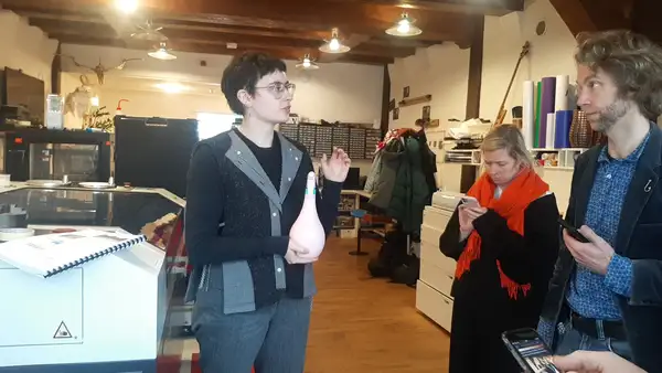
Michelle and Henk show us the two vinyl cutters in Fablab Waag and also their secondhand but for Waag new lasercutter. I will work mostly at the equipment at Fablab Arnhem. I have already worked a lot with the lasercutter and vinyl cutters so for me there is not much new to learn about the how the machines operate and work. It’s fun to see al the similarities and we share recognizable stories about things that have happened with the machines at our labs. The machines are of course not exactly the same as the machines I work with but the workflow is the same. Below you find useful information of al the machines.
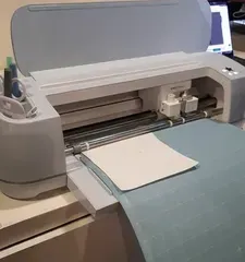
Vinyl cutter - Roland GX-24
- load the foil using the back handle, press down to put the material in and press up to load.
- Make sure the cutter wheels are aligned with the marks above
- Send the file using Mods.
Mods program design bij fabacademy student to you can work with all kind of machines directly from the browser.
Workflow in mods:
right click in mods and select project
select open projects
open the machine in this case Roland GX-24
load a black fill vector image to cut out
change things like size, rotate etc.
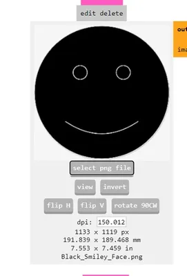
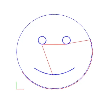
create the toolpath
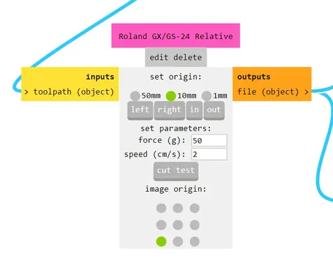
Connect the machine you want to use.
For windows follow the steps in the documentation to install Zadig utility.In Zagid utility, select and replace the machine driver with WinUSB driver.before you send your file you should press on recalculate (ad cut raster).
send the file to the machine.
Vinyl cutter - Cricut
This machine can cut out paper easily and you can put a pen in it to draw designs. Because the material stays flat you can use the cricut for cutting coper tape and other materials using the sticky cricut mat.
The machine has it’s own program were you need to make an account to sign in and actually upload your design file in the program. It guides you step for step. Michelle shows us quickly how to make a design with it.
Lasercutter Waag - BRM 90130
This machine has a 150 W Co2 laser and it uses the software Lightburn.
 Operation
- Stand on the red box when operating the machine.
- Turn it on with the red button on the size, also press the button next to it.
- With homing, watch out for thick material because the axes will move to its home in this case the lower left corner.
- Move the head with the arrows on the machine panel. This avoids mistakes with the z axes on the screen.
- Computer operator is under the machine, you work on the screen on the left side and log in with the password.
Lightburn software
- Don’t change the current position button, this will make the lasercutter start at its current position.
- Load your design
- Tip: Edit -> del duplicates and other useful stuff for cleaning op the designs.
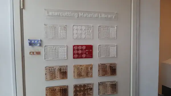
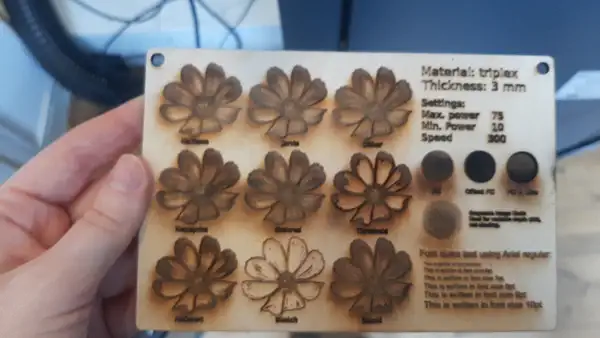
- Material library inside the machine with presets and on the door with physical samples.
- Chose the material you want to cut and measure the thickness and assign the material.
- Frame the file from Lightburn -> to create the outline. Square and elastic!
- Green dot is the starting point from the lasercutter the origin. Show last position to run a trace twice.
- Power and speed, power is a bit higher in the corners the - power is burning the edges make the corner power 10 percent less to prevent this.
- Mode: cutting or engraving, double click on the settings to set the fill or the stroke for engraving.
- Change the order to first engrave and then cut.
- Shortcut alt P for the preview.
- Put in the plug in to put the extractor on.
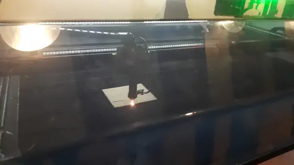
Start the machine
- For the focus of the lens, unscrew both screws on the front side of the head and use the acrylic block to focus the head with the cutting material below.
- Press start from the screen
- First put the machine on before sending the file..
- Spray bottle in place in case of small fires.
- Use tape and weights if necessary when material can move or when the plate material is crooked. You need it to be flat.
- Wait a few minutes before opening the lid because of the fumes.
Image engraving
- A new mode will pop-up in Lightburn if you import an image. You will see various settings for making different image engravings
- We tried it with a Furby picture to make Edwin happy!
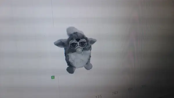
- Happy Henk with the end result, very bad picture on my side unfortunately. My phone has a shitty camera but also something seems of with the settings so I need to check it out.
 technical part
 - Machines don’t think for themselves everything that goes wrong is on you!
- There is a Co2 laser in the back and the laserbeam is directed with mirrors to the head of the machine. There is the lens that will bundle the laser after you focused it.
- Put on the air compressor, the water-cooled and the machine (right now it’s all with the same button).
- The air compressor prevents the material from burning.
- When cleaning the lens : curved size must be facing upwards.
- Lens must be fixed so it’s not loose and moves around in the corner.
- Once is a while clean below the laser bed.
Group assignment
testing the lasercutter at Waag
I did the group assignment together with Leo. We don’t have a group page for this work, our local instructor Henk tells us to put a link you each other pages if enough for this week. I did the assignment with Leo you can find his work here.
- I made the kerf test
- And I made the focus test
- Leo made the offset test he worked on it a bit more and made this very nice explanation since visualizing the kerf and offset can be hard at first, especially if you need to add or remove the material in your design can be abstract thinking. You can find Leo’s explanation below:
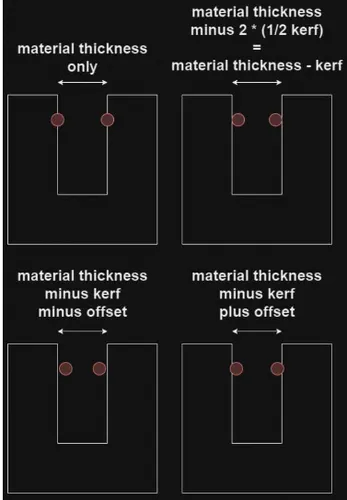 kerf the width of the material that is burned away by the laserbeam.offset material does not always fit one on one, wood is much softer than wood and therefore has a different fit with the offset test you can add and remove (in small steps) bits of material to see what is the best fit for the material.
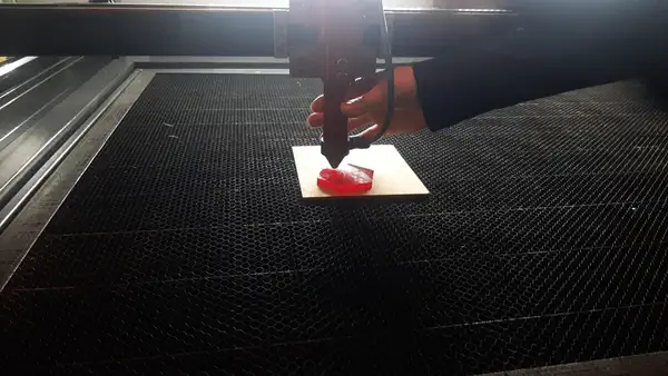
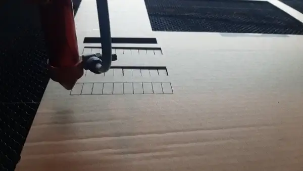
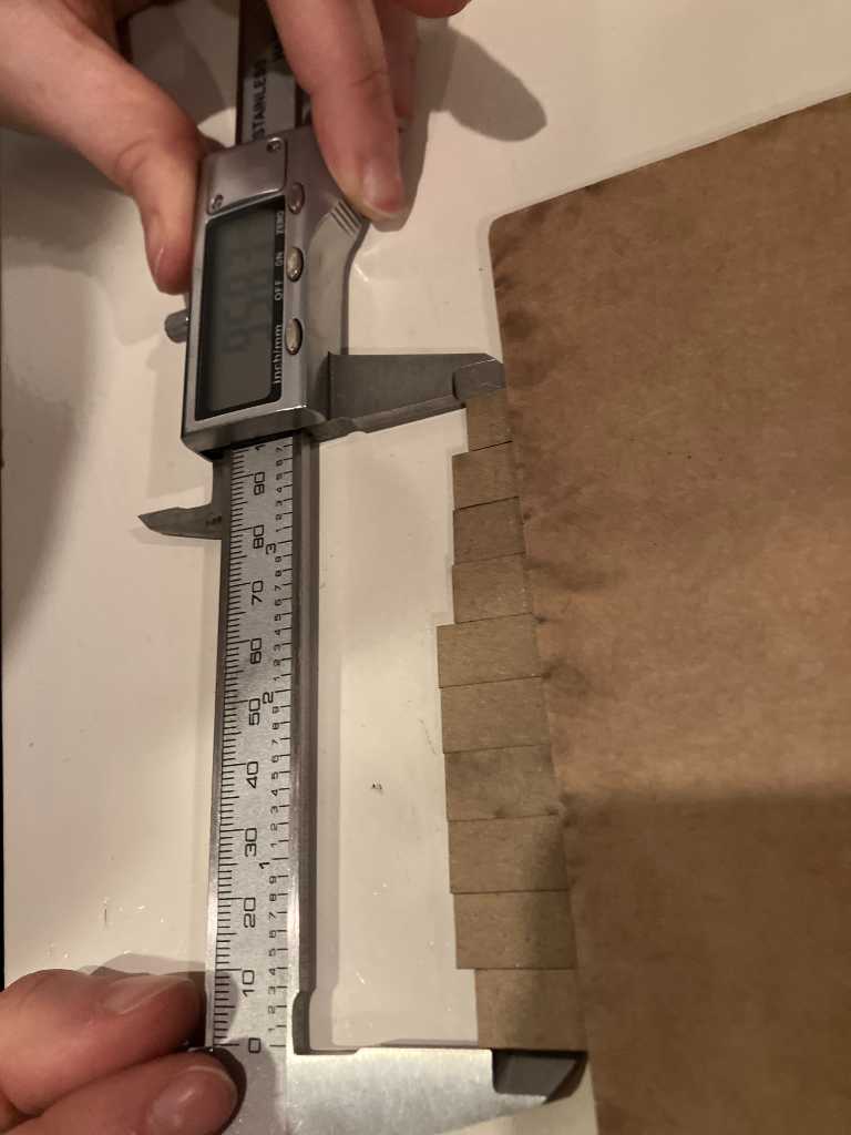
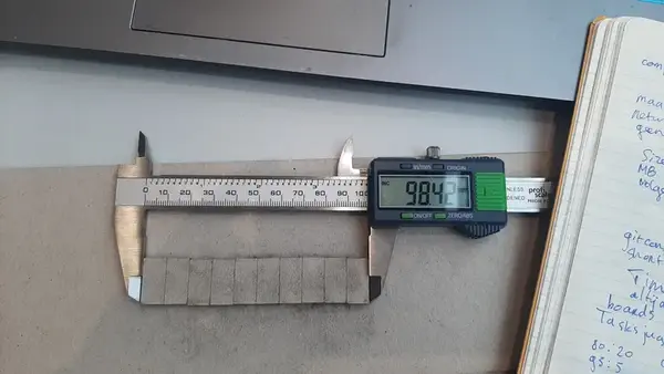
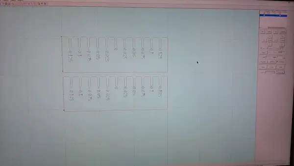
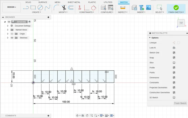 For the kerf test I’ve made a design of 10 boxes of 10 mm width all together 100 mm. And I cut it using the steps describes above. We decide to start with cutting cardboard and we measure 95,83 mm width this is the total amount of material that is burned away. We counted 10 kerf’s in total. The end and start line are both a half kerf so we counted them as one + 9 line in the middle.
We used the following formula to measure the size of the kerf:
100 - 95,83 = 4.17 / 10 = 0.417 mm cardboard kerf
This is a very large kerf, which means there is something wrong. We start with a focus test Edwin drew.
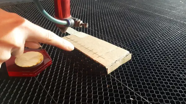
The focus test is very odd because on the highers part the laser is in the best focus leaving only 1 or 2 mm between the head and the material. This can’t be good. So we open the head and there is a white ring inside the head and Henk thinks this ring is in the wrong place. It could explain the odd focus. We change the order of the ring and the lens so the the position of the lens inside the head of the laser is higher and we try another focus test with a folder peace of cardboard.
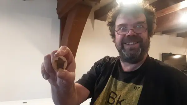
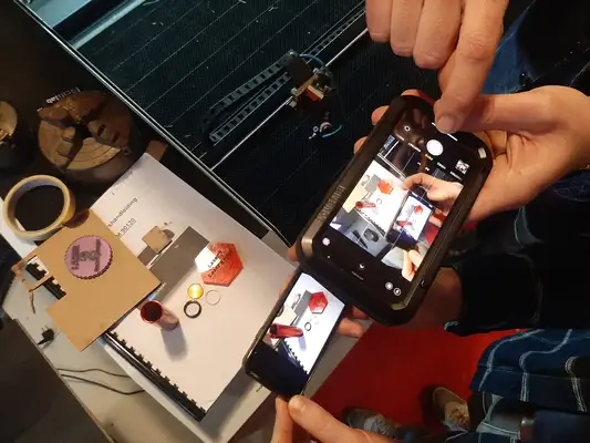
And of course we cleaned the lens. Henk uses a dust free pad and some lens cleaning liquid and a cotton swab. I take a picture of the documenting loop Erdin, Leo and I got ourself in wanting to take a picture of the lens. !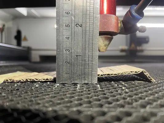 machine testing
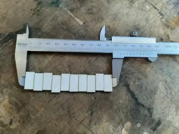
We measure again and now the focus seems to be 2 cm. We try to cut out the kerf test. And we measure a new kerf:
100 - 96.89 = 3.12 mm / 10 = 0.302 mm cardboard kerf
machine testing
We measure again and now the focus seems to be 2 cm. We try to cut out the kerf test. And we measure a new kerf:
100 - 96.89 = 3.12 mm / 10 = 0.302 mm cardboard kerf
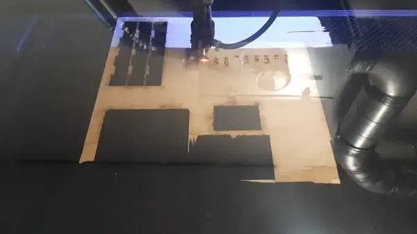
This is still not good for cardboard. So we have the idea that the focus might still be wrong. We decide to make a new focus test using my design template for it instead of the folded cardboard. And this time we want to cut it from wood. When we are cutting the wood the laser does not cut through the material.
 Even with a second pass and with 75 power and 25 speed it won’t cut through 3,5 mm wood. Henk takes a look at is and noticed the head of the laser is a bit hot. This is not a good sign. The lens might not be on the correct position or the mirrors can be out of focus. You can put a peace of tape on the mirror and with a pulse you can check if it’s badly out of focus. It is the case and it needs a bit more time fixing. the lens is put back to it’s original position and Joe is able to cut something good on it! These types of problems are very common for us at the Fablab Arnhem to and it takes some time to get to know your machine, especially when you have a new machine. we are not able to finish the group assignment on the lasercutter at Waag but I will use the lasercutter at the Fablab Arnhem to cut the tests Leo and I made today. I will also make my personal assignment on this machine.
Individual assignment
Construction kit idea
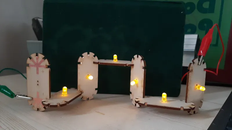
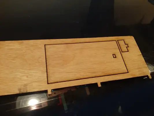
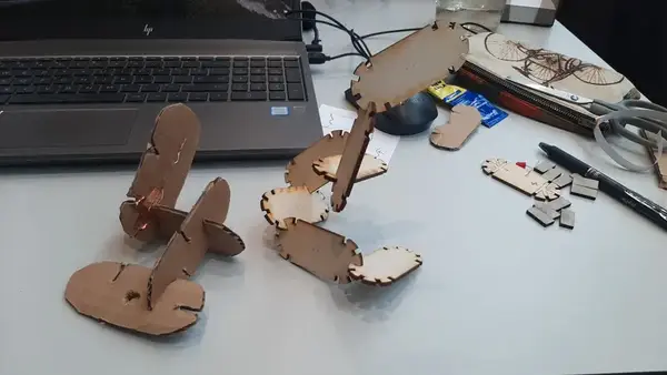
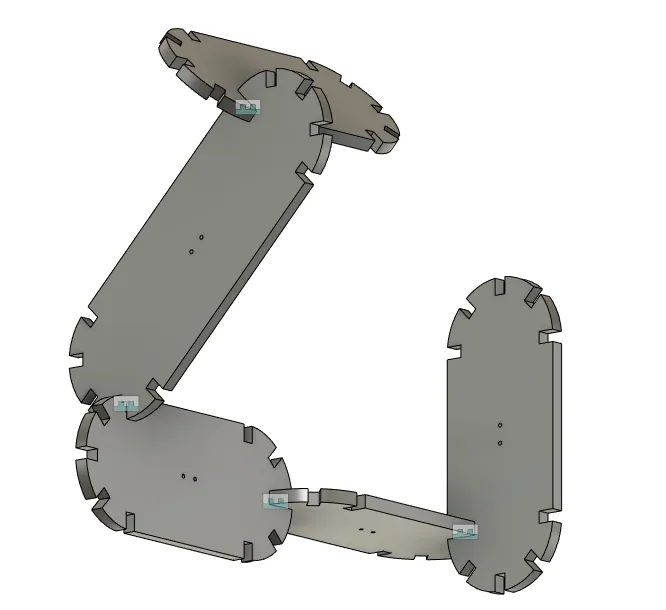
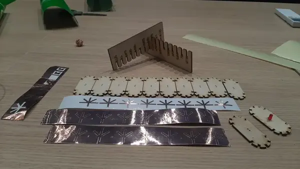
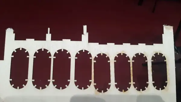
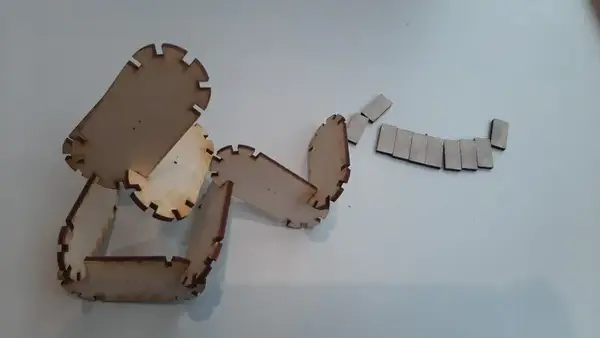
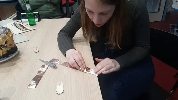
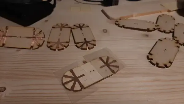
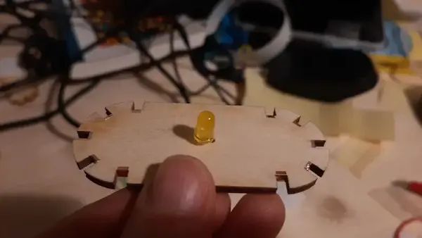
For the construction kit assignment I have the idea to make LED units that, when pressed together with a fingerjoint they connect and make a row of LED lights. So you can make your own lamp. For this idea I want to combine the vinyl cutting assignment and the construction kit assignment. I want to cut copper foil tape to make the conductive connections. I start with sketching my design on paper and I make a prototype using cardboard and a scissor. You can see my cardboard try out on the left and the wooden lasercutted parts on the right side.
Parametric design in Fusion360
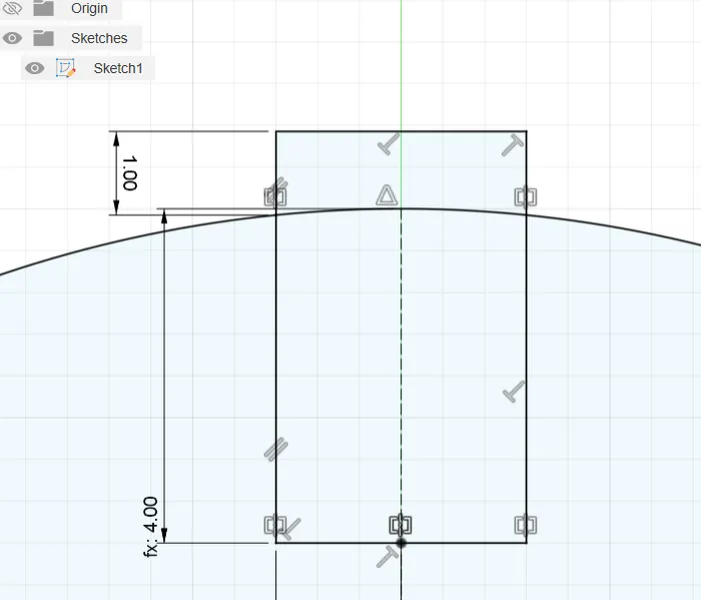
I start with the 2D sketch of the outer shape. I give the diameter of the circle a parametric dimension and I do the same with the length of the shape. To make the fingerjoint I start with sketching a center rectangle And I add a parameter called jointwidth and jointheight.
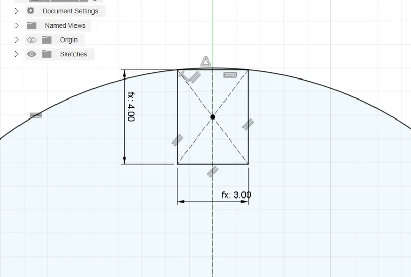 I’m left with a small shape on top of the square and when I trim it my constrains are gone and I want to draw as clean as possible so I decide building the shape with the line tool instead. My fablab Arnhem college Niels gives me the tip to use the = (equal) constraint instead of the dimension parameter for parts that are the same. It makes your design less big and the calculations quicker and it helps limiting unnecessary number in your sketches. I use the mirror tool to mirror the two lines I draw and then I extruded the base. I want to start with the patterning in the sketch but I can’t pattern the slot as a feature because it’s still a sketch.
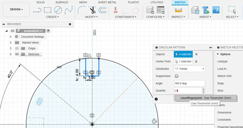
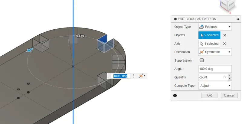
 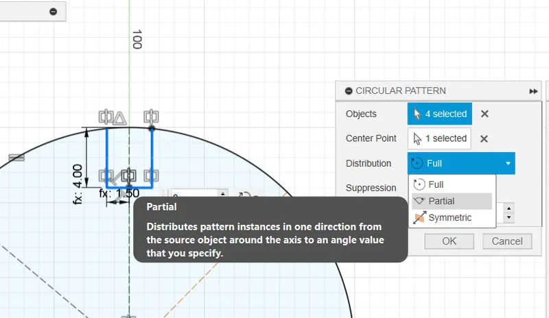 I use the count parameter as the quantity And I set the distribution to partial 180 degrees since i don’t want the slots divided 360 degrees. I see that the start pont is the slot in the middle, If I were to use this technique i need to draw the first stol on the left side.
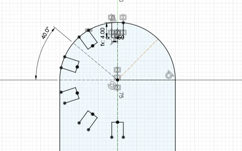
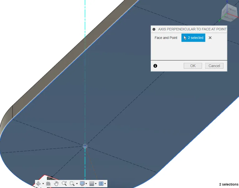
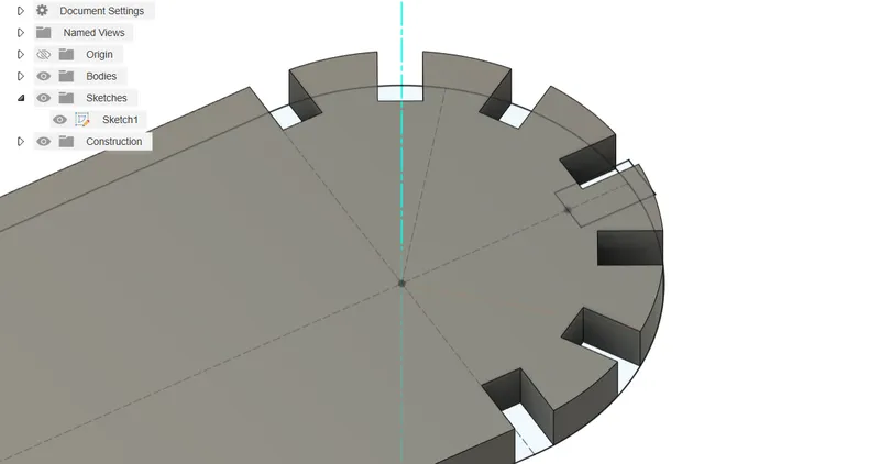
I need to rethink my design decisions and discuss it with my college. I will start extruding the sketch of the body without the slots and afterwards cut extrude the slots and then use the extruded cut feature for the circular pattern with a will mirror afterwards so both sides are the same. I need an axis to rotate the circular pattern around. I create the axis in the mid point of the circle using construct -> axis perpendicular at point
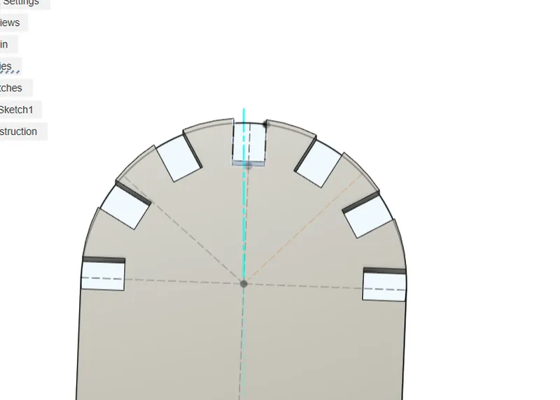
 And I need a midplane in the direction I want to use as a mirror plane. I use the construct -> target plane on the outer curves of the shape and create a midplane.I draw a new sketch for the cut extrude slot and this wil be the feature I will use to create a circular pattern. This way when I change the count in my parameters I don’t have to rebuild the extrusion. The symmetrical distribution fixes my problems from above and I set the angle at 180 degrees. At this state it looks good!
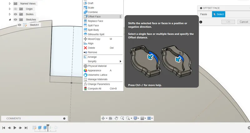
I create an offset face for the slot with the kerf formula + offset Leo and I calculated earlier using the tests. I have had the plug-in Save DXF for laser cutting installed before fabacademy, here you can easy select the sketch you want to export and give it the right offset, but for this project I made the offset in the design file so when I save the sketch al the dimension are perfect.
I see a small problem, the cut extrude is not long enough for the outer slots since the circle ends here and goes into a straight line.
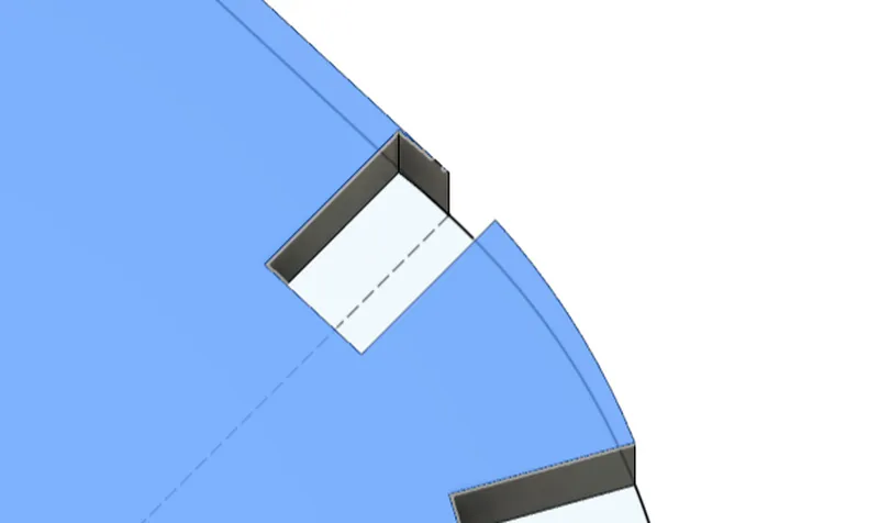
I fix it by making a drawing of a box on top of the slot and make sure this is added to the cut extrude feature to give it more length and this fixes the problem. I change the parameters and check for errors everything works fine!
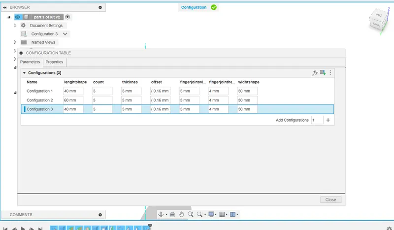
configure
before I make the assembly I try out the configure function. You can choose which parameters you add in the configure so I choose the ones I want to change. This allows you to make different iterations of the model in the same part, you don’t have to create multiple files.
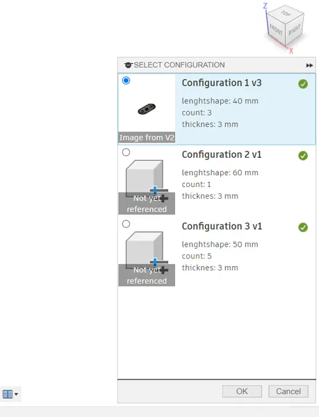
When you load the component into an assembly later, a selection menu will appear and you can choose which configuration you load. When you then change the configuration in the original model, it changes in the assembly to!
It works super easy, first select configure -> configure click on the parameters symbol (fx), add the parameters you want to change in the configuration.
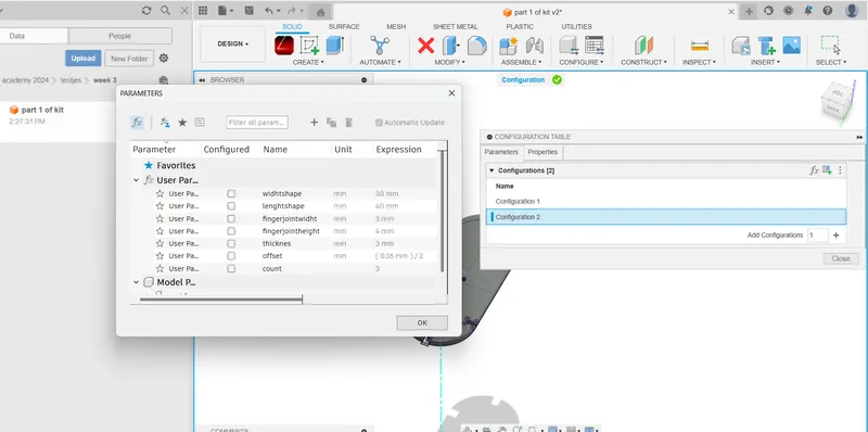
Click in the right below corner on the + symbol next to add configuration and change the parameters! You can see a video of this on the top of my page as my hero shot.
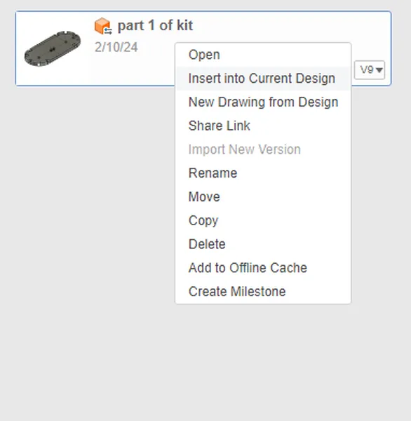
Assembly
I now make a new file and call it assembly. I right click in the menu on the left side of the screen and I select insert in to current design. A menu pops up where I can choose the configuration I want to insert!
I duplicate the model to make the assembly and after this I right click on the part I want to ground so that this part will stay in place.
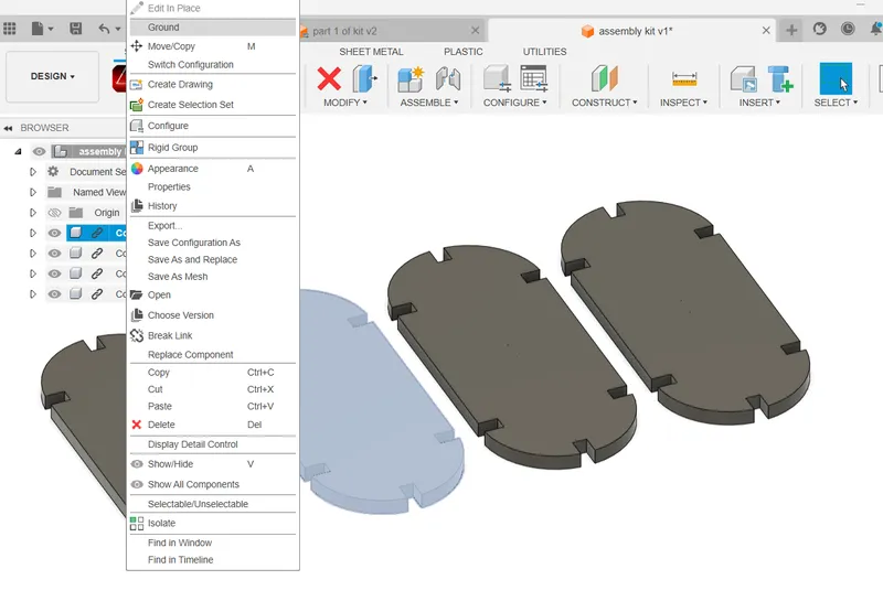 I use the assemble -> joint tool to join two surfaces. With the shift key pressed I can easily select the middle of the plane. After some try and error I understand that you first select the floating object and then select the object connected to the ground. I also used the degrees to sometimes turn the object 90 degrees so it snaps together.
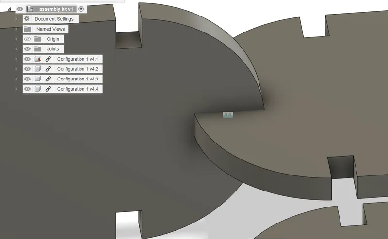
cutting the parts
Export for cutting
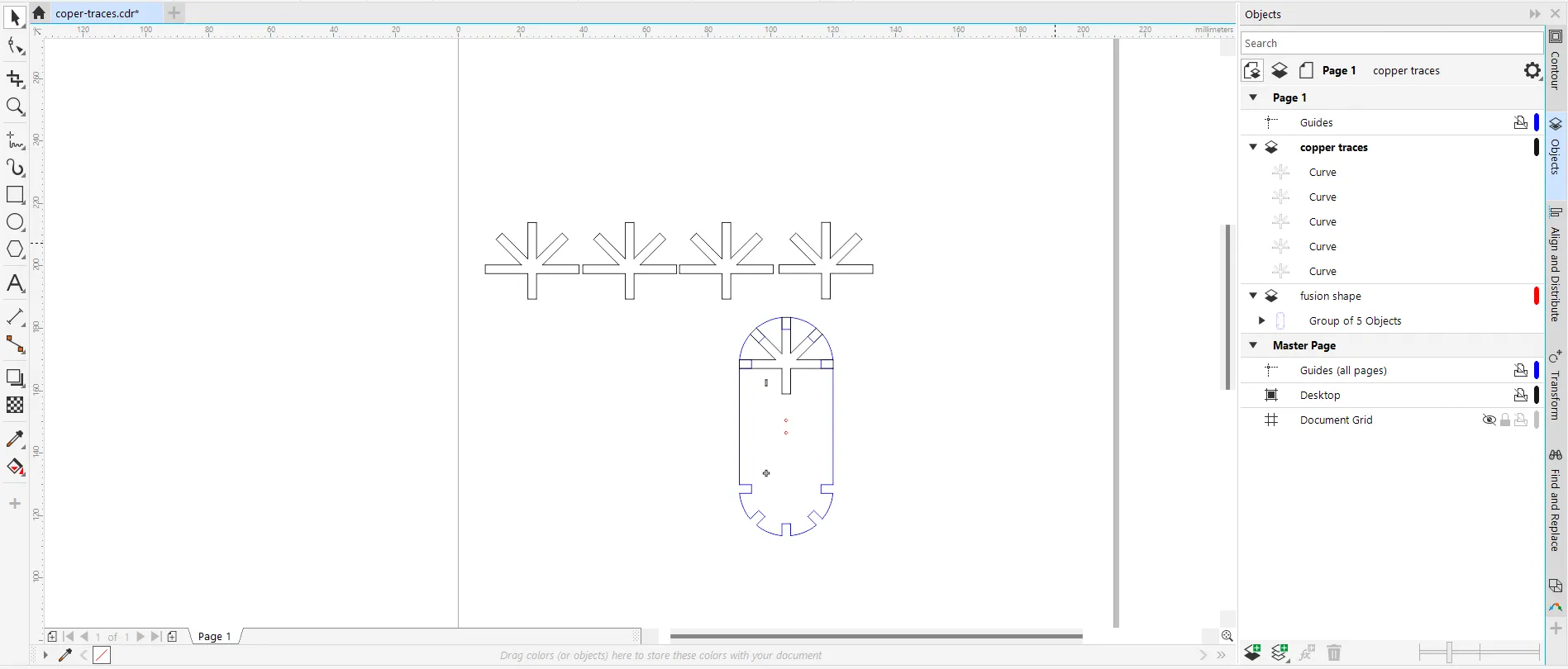
After this I export the design for cutting using the plug-in tool and I put the offset to 0 because it’s already in the design file. I open the DXF in CorelDraw and add a plus and minus using the box tool and weld tool for engraving. I use three colors so I can put different outputs, Red and blue will be cut and black will be an engraving.
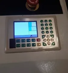
lasercutter BRM 90120 - Fablab Arnhem
100 watt CO2 laser Software: Lasercut 5.3
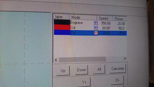
At our lab we made a video how our machine works fom importing the files to cutting out a peace. You can find it here, it’s in english. It shows how to put the setting in the machine and it shows our list of material settings were you can read the speed and power. The safety rules are the same as I described for the lasercutter in Fablab Waag. I’ve used this machine countless times and also teach people how to work with it. For this machine we have made lots of test and gathered the settings for cutting, line and full engraving in a sheet where you find the average settings per material. Of course sometimes it needs tweaking. We have an average kerf of 0.16 mm for 3 mm plate material. I tested it with wood and cardboard and the kerf I calculate is 0.16 mm for cardboard.
For the most perfect fit I cut the offset test Leo made. And although 0.16 mm offset usually fits very good for 3 mm wood, I discover that the offset of 0.075 mm on top of the 0.16 mm kerf is an even tighter fit. I use the following settings for cutting: 20 speed and 50 power.
 So I end up with the total offset of: 0.235 mm. This makes a very tight pressfit.
Later in the process I'm bummed that I pushed the limits with this pressfit because the 0.16 kerf was already tight enough to keep everything in place and because I made it even tighter the copper tape had a tear issue. In the future I will remember this. Also if you make things that snap together in multiple places like boxes you probably need a bit more clearance to
For me the best workflow with the kerf and offset is to have a general kerf like 0.16 for 3 mm material and use an offset test like Leo made to test the right fit for the purpose. I think measuring the kerf first and than an offset test is a bit of extra work not really worth it.
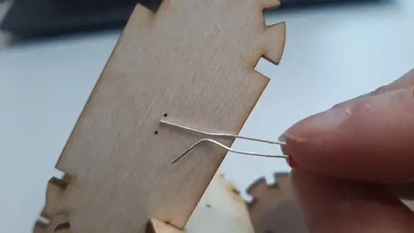
At this point the fingerjoint fit perfectly but I have an other issue.. In Dutch we have a saying called “meten is weten” You can translate is as measuring is knowing. Well I didn’t measure the legs of the LED’s and just guessed it and than forgot about it. So the holes are to tiny. I measure and change the diameter of the holes in Fusion and do a second run and when I know it fits I make some more shapes using leftover plywood 3 mm from the fablab Arnhem.
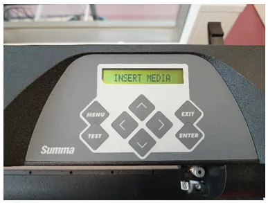
Summa vinyl cutter - cutting coper tape
Now I will start cutting the copper tape for the conductive traces. I get the tape at the local Intratuin store and it costs me €6,- for 5 meters long and 3,5 cm width copper foil tape. I took the width of the roll into account before I started 3D modeling so I knew it could fit.
I start Corel Draw and I open the DXF file from fusion. I start with creating a new layer called copper traces on top of the first layer. With the pen tool I trace the shape where I want the copper tape to be. I also use the weld function to merge the shapes together. Put them in a row and export only the copper traces layer as a .EPS file I open the software Summa winplot and open the file.
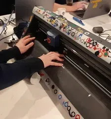
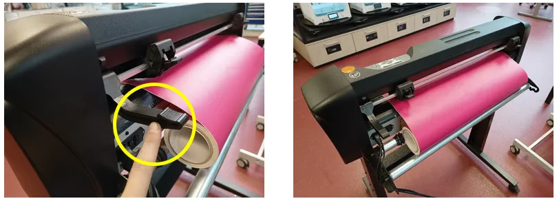
I put a peace of the copper tape on a sticky cutting mat from the brand cricut and I lift the handle in the back of the machine, put the guiding wheels so the material fits between. In the pictures below, from Fablab Arnhem, you can see how to load the material.
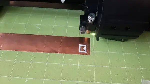
 I to load the mat in the machine. I do 5 test runs with the knife pressure before cutting out my shape. The right amount of pressure is 10 grams.
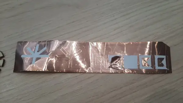
I start weeding the copper tape and this is surprisingly easy!
 After this I use the transfer foil to properly transfer my stickers to past them in place on the construction kit parts.
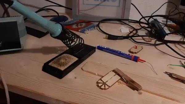
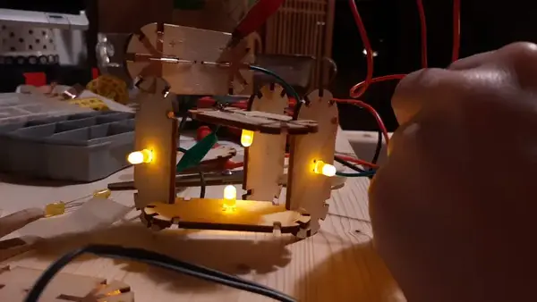
Soldering the LED’s
I start soldering the LED’s on the copper tape. I have a 3 to 12 V, 200 mA DC adapter. I looked up in the datasheet of the arduino starter kit that the yellow LED’s uses 2.1 V with a minimum of 1.9 V
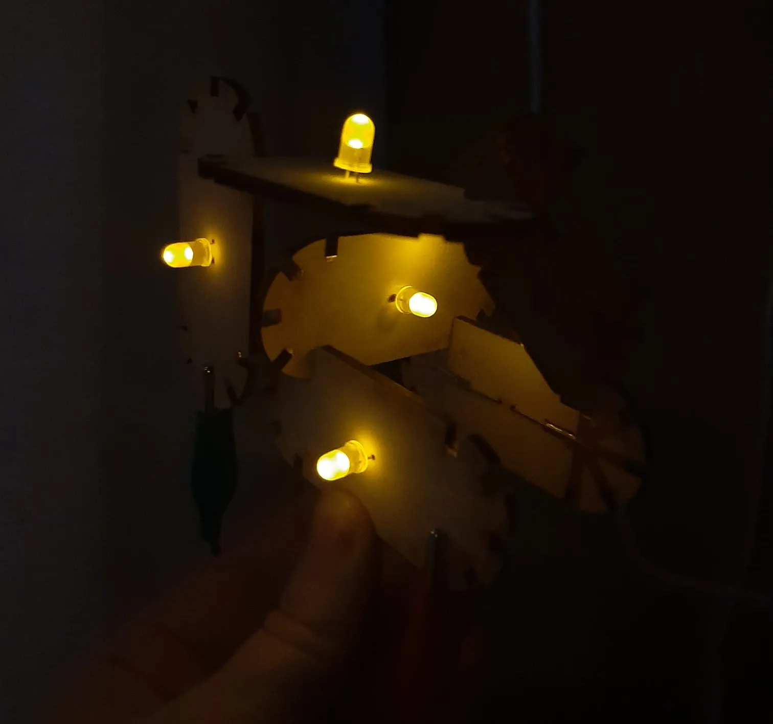
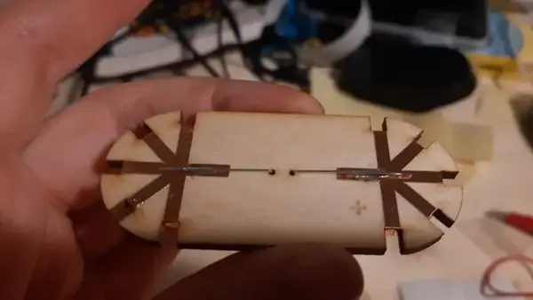
I solder three LED’s and use my multimeter to check if the copper tape connections are working before putting the adapter to 6 V. It works! When I loosen the joins again I see that the copper tape is damaged. The fit is to tight. I sand down some of the edges. A chamfer in the design would have helped and also a less tight fit. I decide to finish the kit and with this adapter I can put 6 led’s in a row. I assembled them carefully trying not to rip the copper and I’m very happy with the result! A lot of new ideas pop into my mind about designing a really big light this way or making the kit with a parallel circuit instead of the series circuit it now is.
I remember it is open time and jump in to a zoom call. Ardian asked me some questions and I shared my stuff with is pretty nice after working at home on the weekend. After the call I decide to leave the kit how it is, it took me a couple of hours to weld and sticker everything. I’m going to work on my documentation first and I want to try some stuff with the vinyl cutter for my final project. I got new inspiration and things I want to check out from the call for my final project and that was very nice!
files
- Download the fusion part and assembly file here
- Download the copper traces for the vinyl cutter file here
Things I messed up and learned from
This week started out very familiar the lasercutter and vinyl cutter are machines I know well and I had no clue what to make for the construction kit because I didn’t read the assignment and already head the idea to make something else (a rotocaster) but that went out the widow when I read about the construction kit.. When I got the idea of the LED units under the shower I was really exited because a big wish for me is to learn more about electronics and I could merge the sticker assignment. I got super exited about the making and slightly depressed about the documenting afterwards haha. Once again I did not document as I go, I do make pictures and screenshots but I don’t type, this is still a learning point for me. I also see that I have little patience making good pictures.. Another learning point. I think it’s because a lot of things this week (about the machines) were already in my head the need for myself to document it feels less urgent. But I think it’s al on this page again and I’m happy about that. As a last learning point I would say try to think the best you can about how you are going to design something parametric before jumping in. Out of enthusiasm I didn’t give myself the time to think it out properly.