Week 14
Interface and Application Programming
| group assignments | — |
|---|---|
| Compare as many tool options as possible. | |
| Document your work to the group work page and reflect on your individual page what you learned |
| individual assignments | — |
|---|---|
| Write an application that interfaces a user with an input and/or output device(s) on a board that you made. |
Notes from Neil’s lecture
This week will be about building software applications interfaces for users. This application will interact with one of my embedded devices.
To build an application you need a programming language. There are many languages available. In the Arduino IDE I have been writing C++, you can also use this on the desktop but there are many languages whom might be a better fit this week. Why? Well the following languages are all types of languages to help fix stuff that can go wrong (like safety and sustainability) in C. These are all function languages:
- Go, Rust
- Flutter, Dart
- Kotlin, Swift
There are many more languages that can be uses this week:
- Bash, Tcl are scripting languages
- Perl, Ruby, are in the same domain as python
- APL, language to do math
- Python, takes the object structure of C++ and it’s taking operations like APL.
- Python environment, conda can help manage. Neil recommends python to program on the computer.
- Javascript, for web applications:
- Processing, feels like arduino on the desktop so it can be nice to try out if you like arduino.
Neil recommends learning Python, Javascript and Node-Red or mods to do data flow programming.
- Mods has modula to generate websocket events, instead of making lines of code it’s a graph to run data trough. You can export the workflow of mods as an HTML page.
- Node-RED framework is used for building data interflow, you make a diagram of the elements you are using for example a button and led, it build the code and runs UI on top of it.
Talking to your micro controller
How do we get my device to talk to the micro controller with inputs or outputs? this can be done via serial communication using the USB connecting. Python and arduino also have I2C communication protocol.
- XMPP,IFTT : helpful for devices that don’t know each other to talk to each other.
MQTT Lets you send info or much different sensors and actuators, if you want to visualize the data and put controls to it to do something it can be a nice fit. MQTT is a framework simple to understand and use. Mosquito is a broker of MQTT
- Start a MQTT broker: the broker is what hosts the communication it’s at the hart of the system. You can run a broker locally, Julian set up a broker you can use for Fabacademy.
- MQTT has channels and there is publishing and subscribing. The micro controller and the terminal are both connected to the terminal. Via the browser, in javascript, add a webpage thats also connected to the broker. A message goes out to everybody who’s subscribed to that channel. If you need 10 ms response it’s fine but not faster.
Data will flow How to handle the data?:
- JSON will help structure data
- TOML same thing with clean syntax It’s a structure file with names that turns into objects. For large amounts of data you can use Pyspread, Pandas, MySOL, MongoDB
Workshop at Waag from Bas
Comparing workflows:
Processing
Runs on Java and looks very much like the arduino IDE. You have no security concerns because it runs on the laptop, quickly a graphical idea is made. With Java there is a ig downside because there is a license problem. Oracle changed the license model and you can get in payment problems because of it.
Processing is based on 2 functions
- void setup -> runs only once
- void draw-> loops 60 times per second (default framerate)
Tips:
- The order of the commands are very important if you put the background at the bottom of the code it will overlap all other coded visuals things. Similar to layers in Illustrator.
- You can’t just take processing language and run the application on any webbrowser. You have to make sure you export the code for the right system, meaning Apple or windows, Iphone or laptop. This takes more time to set up than P5.js.
P5.js
More and more processing is replaced by P5.js it works similar to processing but with Javascript instead of Java. And It’s a web based programming environment. P5 makes it look easier then it is, the program also uses HTML ans CSS to build this but it’s hidden. The benefits of P5.js over Processing are: it’s better and better in communicating with devices on your computer, and because it’s a web environment you can directly show it to people.
P5.js is based on 2 functions
- function setup -> runs only once
- function draw -> loops 60 times per second (default framerate)
In visual studio Code you can run P5.js by installing the following extensions: (search P5)
- Live-P5
- P5.vscode
To start a new program press FN * F1 and type P5
- create a new p5. project.
- open a live p5 panel to look at the visualization of the code directly. By saving you start the sketch
Coding tricks
Bas shows us his favorite tips and tricks and a quick introduction via his webpage here with lots of examples. I made a few notes on it:
xPosition : moving
XVelocity: point towards were the object is going to be in relation with the last frame.
Code structure : there are tricks to make your code as simple as possible.
Class is a bundle of objects, like a recipe and the objects are the dishes.
random for function to randomize things
array variable that is a list of multiply things
cntrl. D to select the same word and change them all at once
Only in Chrome, Edge and Firefox can work with webSerial! Caniuse is a website to check these things.
You can’t open a serial port in the webpage; there is a user aces involved in opening serial port so you have to give it aces. With a key or button to open and close the webserial.
Sending Data
Variables
- " " = string
- ’ ‘= character (characters are easier to send)
- String: it’s text but it’s send as numbers. There are ways to interpret the byte Numbers above 250 are sending more bytes
Serial.print: sends the string to separate characters that you needs to set back together again.
Serial.write: sends the actual number
They are both difficult.
Just send single bytes: map the value from 0 to 255 to send one byte.
ASCI color: #F00
J-son library to deserialize the string data. just names you can see and read it, it has more overhead.
webSerial
Websockets are a network connection between the device and the application without having to restart the connection over again. It’s like a channel between the two devices to send data both ways, you won’t get it for free. It takes work to set it up. You need a third thing in the middle that called a socketserver. Both needs to be connected. The laptop and the device. And this socket server needs to be somewhere on the www.
MQTT is easier to start with if you already have a broken because you don’t have to set up a socket server.
building on the group assignment
I will start by testing the part Joany and Leo worked on during the group assignment. At the same time I had help from Bas getting to understand my struggles with BLE from last week assignment, this took a lot of time so I missed the group assignment. Joany and Leo were kind to take me through what they have done sofar and I will try to replicate it and build on it to start this weeks assignment. So I’m going to make a connecting via arduino UNO and P5.js webserial starting with making the arduino Uno sending 0’s and 1’s to the webserial.
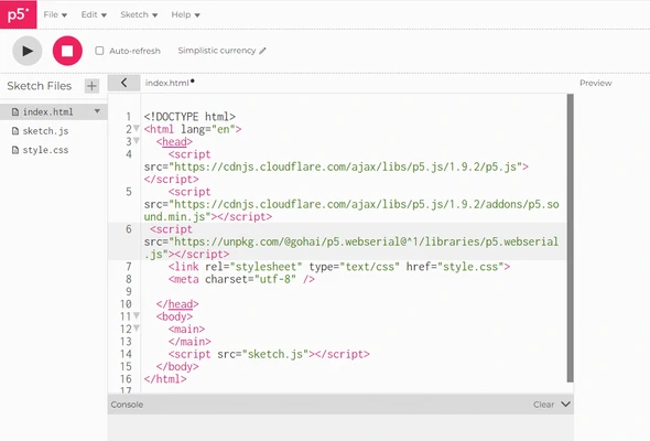
I start with importing the web serial from gohai following the first step and pasting the library in P5.js. By copying the following code <script src="https://unpkg.com/@gohai/p5.webserial@^1/libraries/p5.webserial.js"></script> and going to the web editor of P5.js and pasting it in the HTML file by clicking on the secret open-up side menu arrow with the pick color in the screenshot below. Open the HMTL tab and paste it underneath the other library’s like you see in the second screenshot.
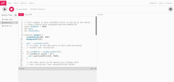
I used there sample code, you can find it below, and after uploading the code in the Arduino IDE, I could not connect the arduino serial from the webbrowser. It was already occupied. So make sure to close the arduino IDE or disconnect the USB serial before you connect the serial in the P5.js web environment. I clicked on the button select the COM port and I see floating 0 and 1’s. The only problem is they are coming in pairs. so I add the ln after the print commando to make sure to fix this.
P5.js code sending 0’s and 1’s
// This example is also available online in the p5.js web editor:
// https://editor.p5js.org/gohai/sketches/X0XD9xvIR
const BAUDRATE = 9600;
let port;
let connectBtn;

function setup() {
  createCanvas(400, 400);
  background(220);

  port = createSerial();
  // in setup, we can open ports we have used previously
  // without user interaction

  let usedPorts = usedSerialPorts();
  if (usedPorts.length > 0) {
    port.open(usedPorts[0], 9600);
  }

  // any other ports can be opened via a dialog after
  // user interaction (see connectBtnClick below)

  connectBtn = createButton('Connect to Arduino');
  connectBtn.position(80, 200);
  connectBtn.mousePressed(connectBtnClick);

  let sendBtn = createButton('Send hello');
  sendBtn.position(330, 375);
  sendBtn.mousePressed(sendBtnClick);
}

function draw() {
  // this makes received text scroll up
  copy(0, 0, width, height, 0, -1, width, height);

  // reads in complete lines and prints them at the
  // bottom of the canvas
  let str = port.readUntil("\n");
  if (str.length > 0) {
    text(str, 10, height-20);
  }

  // changes button label based on connection status
  if (!port.opened()) {
    connectBtn.html('Connect to Arduino');
  } else {
    connectBtn.html('Disconnect');
  }
}

function connectBtnClick() {

  if (!port.opened()) {
    port.open(BAUDRATE);
  } else {
    port.close();
  }
}

function sendBtnClick() {
  port.write("Hello from p5.js\n");
}
Arduino IDE code sending 0’s and 1’s
void setup() {
pinMode(13, OUTPUT); // set LED pin as output
digitalWrite(13, LOW); // switch off LED pin
Serial.begin(9600); // initialize serial communication at 9600 bits per second:
}
void loop() {
Serial.println('1');
digitalWrite(13, HIGH);
delay(3000);
Serial.println('0');
digitalWrite(13, LOW);
delay(3000);
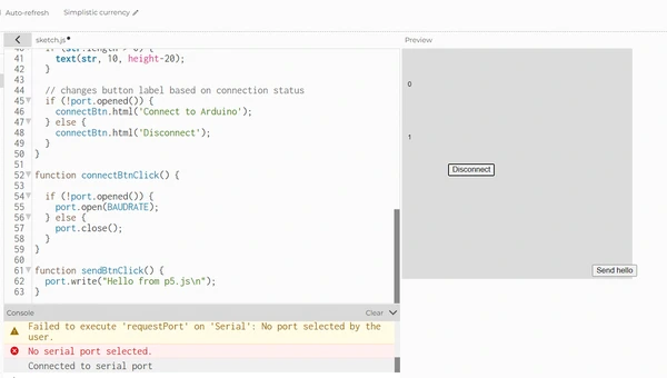
}Here you can see the program working. the arduino is sending 0’s and 1’s every second and the web environment P5.js is showing this.
 . There is another button in the code with send Hello. in the code it’s I found this sentence
 port.write("Hello from p5.js\n"); sending this text in double quotation mark meaning a string of text. I’m curious if I can read it in the monitor. So I open the arduino IDE. But of course I can’t have two serials open so I decide to make a LED blink when the button is pressed instead.
Me and ChatGPT had a chat about it and I changed the code a bit because at first I tried to send byte and read it as a string. But I learned from my mistakes last week and fixed this problem by sending a string. The GitHub P5.webserial has a nice overview of different types of writing and reading data. I used port.write(String(1)); to send a 1 and the arduino reads this number and if it’s a 1 turns the LED to HIGH. I have now be able to communicate both ways, from arduino as input and web as output and from web as output and arduino as input. My next step will be to use my own fabricated board and have some fun with this! So adding different inputs, making more graphical outputs and try out different stuff.
P5.js code blinkingLED
// This example is also available online in the p5.js web editor:
// https://editor.p5js.org/gohai/sketches/X0XD9xvIR
const BAUDRATE = 9600;
let port;
let connectBtn;

function setup() {
  createCanvas(400, 400);
  background(220);

  port = createSerial();
  // in setup, we can open ports we have used previously
  // without user interaction

  let usedPorts = usedSerialPorts();
  if (usedPorts.length > 0) {
    port.open(usedPorts[0], 9600);
  }

  // any other ports can be opened via a dialog after
  // user interaction (see connectBtnClick below)

  connectBtn = createButton('Connect to Arduino');
  connectBtn.position(80, 200);
  connectBtn.mousePressed(connectBtnClick);

  let sendBtn = createButton('Send hello');
  sendBtn.position(330, 375);
  sendBtn.mousePressed(sendBtnClick);
}

function draw() {
  // changes button label based on connection status
  if (!port.opened()) {
    connectBtn.html('Connect to Arduino');
  } else {
    connectBtn.html('Disconnect');
  }
}

function connectBtnClick() {

  if (!port.opened()) {
    port.open(BAUDRATE);
  } else {
    port.close();
  }
}

function sendBtnClick() {
  port.write(String(1));
}
Arduino IDE code blinkingLED
void setup() {
  pinMode(13, OUTPUT);      // set LED pin as output
  digitalWrite(13, LOW);    // switch off LED pin
  Serial.begin(9600);       // initialize serial communication at 9600 bits per second:
}

void loop() {
  if(Serial.available()){   // Check if data is available to read
    char receivedChar = Serial.read(); // Read the incoming byte

    if (receivedChar == '1') {
      digitalWrite(13, HIGH); // Turn on LED
    } else if (receivedChar == '0') {
      digitalWrite(13, LOW); // Turn off LED
    }
  }
}
Personal assignment
Neopixel USB connection web interface
I will start with the blinking example and try to blink the Neopixel on my breakout board ESL32-C3 that I made during electronics design week. Using the same code as the arduino UNO just changing the pinMode(13,OUTPUT); to pinMode(7,OUTPUT); This did not work because I forgot a Neopixel needs a bit more work lol. So I start altering the code including the library of the Neopixel and the commands that go with it. Also I’m working with the ESP32-C3 now so the baud rate is 115200. Well this worked the Neopixel is turning ON when I click on the button! Next up is turning it off. I try a few things with if, els statements to turn of the Neopixel. I try to code: iff the button is pressed send 1 else send 0, and put the output to the pin in arduino to LOW when It’s a 0. But I can’t seem to get it to work. I decide to take my mind of it and first watch a bunch of p5.js tutorials from The coding train especially the tutorials about conditional statements within P5.js and also basic intro stuff like:
P5.js is two things
- it’s a library of functions to draw a circle etc.
- P5.js editor, a program that you can type code in.
Besides that I leaned cool tricks about moving your mouse and putting outputs to were your mouse is on the canvas but before I try that I give one more try to turning the Neopixel off and this time I add anther button. Still no success, I want to test if it’s even sending 1 and 0 and for this
I use the following command: console.log('Sending: 0');
Now I can read the numbers it’s sending in the monitor inside P5.js. I see it’s sending 0 and 1’s so the problem must be in the arduino code. At first I think the code needs a longer delay or you won’t see the neopizel turning on when you clicked on the button and it’s sending one 1. But after a bit I think it must be the Write LOW statement and I remember the Neopixel actually uses 5V and instead od the pin output write high/low statements you use with LED’s so that must be it. I change this part of the code:
 else if{
    digitalWrite(D7, LOW); // Turn off LED
 }
To the library function pixels.clear this does not work either so I google it and found out output color 0,0,0, that should turn off the Neopixel. So I try this code instead:
 else if(receivedChar == '0') {
    pixels.clear();
    pixels.setPixelColor(0, pixels.Color(0, 0, 0));
    pixels.show();
    delay(100);
 }
The Neopixel color is made up from 3 colors, RGB and the three numbers in the code (Color(0, 0, 0)) are creating the color. 0 is turning the color off. Since I put all three colors to 0, it’s making the Neopixel shinning no light.
I add a nice background color change together with the Neopixel turning on and off. And I pasted my code within Visual Studio Code, also pasted the library again in the HTML file. From here I went live pressing this little button in the right corner:
 And I connect by ESP32-C in the Chrome browser
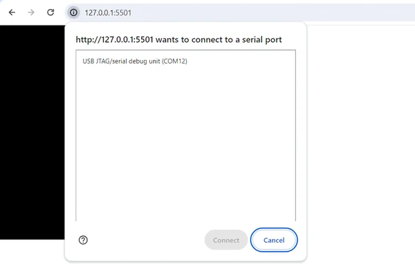
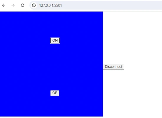
And here is the result
P5.js buttonNeopixel
const BAUDRATE = 9600;
let port;
let connectBtn;

function setup() {
  createCanvas(400, 400);
  background(0, 0, 0);

  port = createSerial();
  // in setup, we can open ports we have used previously
  // without user interaction

  let usedPorts = usedSerialPorts();
  if (usedPorts.length > 0) {
    port.open(usedPorts[0], 9600);
  }

  // any other ports can be opened via a dialog after
  // user interaction (see connectBtnClick below)

  connectBtn = createButton('Connect to Butterfly');
  connectBtn.position(400, 200);
  connectBtn.mousePressed(connectBtnClick);

  let sendBtnon = createButton('ON');
  sendBtnon.position(width/2, 100);
  sendBtnon.mousePressed(sendBtnonClick);

  let sendBtnoff = createButton('OF');
  sendBtnoff.position(width/2, 300);
  sendBtnoff.mousePressed(sendBtnoffClick);
}

function draw() {
  // changes button label based on connection status
  if (!port.opened()) {
    connectBtn.html('Connect to Butterfly');
  } else {
    connectBtn.html('Disconnect');
  }
}

function connectBtnClick() {

  if (!port.opened()) {
    port.open(BAUDRATE);
  } else {
    port.close();
  }
}

function sendBtnonClick() {
  port.write('1');
  console.log('Sending: 1');
  background(0, 0, 255);
}

function sendBtnoffClick() {
  port.write('0');
  console.log('Sending: 0');
  background(0, 0, 0);
}
Arduino IDE ButtonNeopixel
#include <Adafruit_NeoPixel.h>
int PIN = D7;
#define NUMPIXELS 1
Adafruit_NeoPixel pixels(NUMPIXELS, PIN, NEO_GRB + NEO_KHZ800);
void setup() {
pixels.begin();
pinMode(D7, OUTPUT); // set LED pin as output
digitalWrite(D7, LOW); // switch off LED pin
Serial.begin(115200); // initialize serial communication at 9600 bits per second:
}
void loop() {
if(Serial.available()){ // Check if data is available to read
char receivedChar = Serial.read(); // Read the incoming byte
if (receivedChar == '1') {
pixels.clear();
pixels.setPixelColor(0, pixels.Color(0, 0, 255));
pixels.show();
delay(100);
}
else if(receivedChar == '0') {
pixels.clear();
pixels.setPixelColor(0, pixels.Color(0, 0, 0));
pixels.show();
delay(100);
}
}
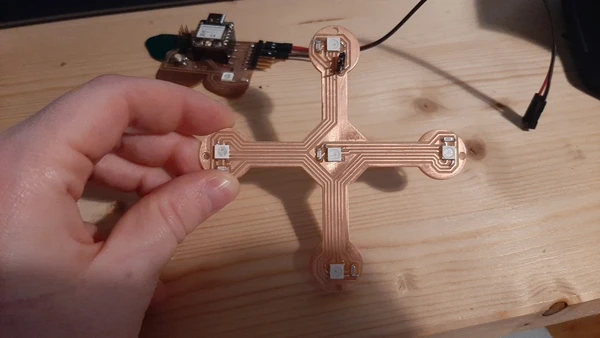
}Neopixels PCB with web interface
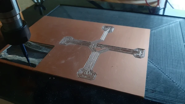
I continued this assignment by designing a new board in KiCAD. I’ve designed and milled a board with 5 neopixels that I might also use for my final project inside the nightlight. But I like to embed it in this assignment doing something interactive with it.
I used the code from above and edited it to by including if (mouseX > 400) { port.write('0'); console.log('Sending:0'); background(0, 0, 255)
The if (mouseX) code line is replaced for the if button is pressed statement and makes it more interactive. If I move my mouse now from the left to the right side of the screen, I can put different kinds of inputs to the orientation of the mouse. The port.write sends the character 0 to the micro controller.
I included multiply if else statements and mapped the mouse to 100, 200, 300, 400 for every movement I let the program send a different value as a value.
P5.js code mouse movements and neopixels output
const BAUDRATE = 115200;
let port;
let connectBtn;
function setup() {
createCanvas(500, 500);
background(0, 0, 0);
port = createSerial();
// in setup, we can open ports we have used previously
// without user interaction
let usedPorts = usedSerialPorts();
if (usedPorts.length > 0) {
port.open(usedPorts[0], 115200);
}
// any other ports can be opened via a dialog after
// user interaction (see connectBtnClick below)
connectBtn = createButton('Connect to Arduino');
connectBtn.position(400, 200);
connectBtn.mousePressed(connectBtnClick);
}
function draw() {
// changes button label based on connection status
if (!port.opened()) {
connectBtn.html('Connect to Arduino');
} else {
connectBtn.html('Disconnect');
}
if (mouseX > 400) {
port.write('0');
console.log('Sending:0');
background(0, 0, 255);
}
else if (mouseX > 300) {
port.write('1');
console.log('Sending: 1');
background(0, 255, 0);
}
else if (mouseX > 200) {
port.write('2');
console.log('Sending: 2');
background(255, 0, 0);
}
else if (mouseX > 100) {
port.write('3');
console.log('Sending: 3');
background(255, 255, 255);
}
else if (mouseX > 50) {
port.write('4');
console.log('Sending: 4');
background(255, 255, 255);
}
}
function connectBtnClick() {
if (!port.opened()) {
port.open(BAUDRATE);
} else {
port.close();
}
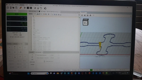
}In the arduino IDE I use if else statements and (receivedChar == '0') { To activate the Neopixels when it’s receiving the character. So for char 0 pixel 1 lit up char 1 pixel 2 and so on.
Arduino IDE code mouse movements and neopixelsoutput
#include <Adafruit_NeoPixel.h>

int PIN  = D10;
#define NUMPIXELS 5

Adafruit_NeoPixel pixels(NUMPIXELS, PIN, NEO_GRB + NEO_KHZ800);

void setup() {
  pixels.begin();
  pinMode(D10, OUTPUT);      // set LED pin as output
  digitalWrite(D10, LOW);    // switch off LED pin
  Serial.begin(115200);       // initialize serial communication at 9600 bits per second:
}

void loop() {
  if(Serial.available()){   // Check if data is available to read
    char receivedChar = Serial.read(); // Read the incoming byte

    if (receivedChar == '0') {
    pixels.clear();
    pixels.setPixelColor(0, pixels.Color(255, 255, 0));
    pixels.show();
    }

    else if(receivedChar == '1') {
    pixels.clear();
    pixels.setPixelColor(1, pixels.Color(0, 0, 255));
    pixels.show();
    }

    else if(receivedChar == '2') {
    pixels.clear();
    pixels.setPixelColor(2, pixels.Color(0, 255, 0));
    pixels.show();
    }

    else if(receivedChar == '3') {
    pixels.clear();
    pixels.setPixelColor(3, pixels.Color(255, 0, 0));
    pixels.show();
    }

    else if(receivedChar == '4') {
    pixels.clear();
    pixels.setPixelColor(4, pixels.Color(255, 0, 255));
    pixels.show();
    }

  }
}
Here you can see the codes and my PCB working. I used the butterfly breakout board I made during electronic design to connect the Neopixel unit. I used a ESP32-C3 for this assignment.
Interactive web interface
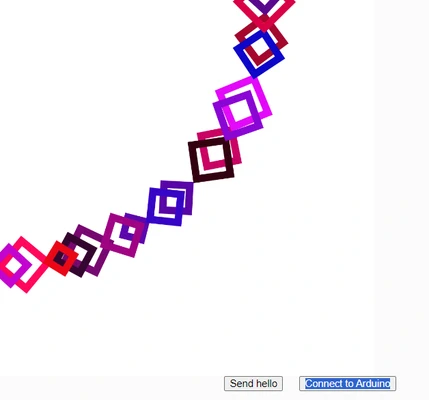
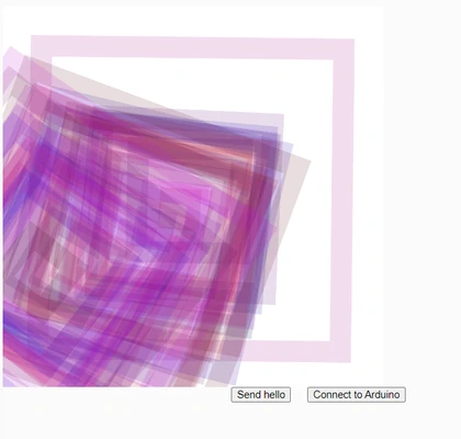
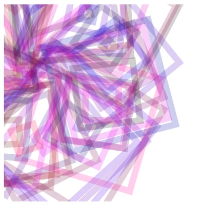
I tried different things with shapes color and rotation and experimented with it. It’s nice to gradually learn how to code with the visual representation of the code next to it.I found the inspiration for this week website inspiration link 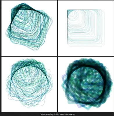 Designs from Jenny B Kowalski.
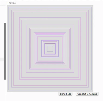
Here you can see the different stages my design went through in screenshots.
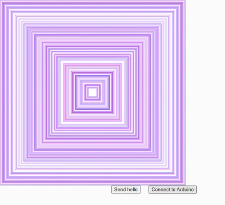
P5.js code interactive squares
let squareSizes = [];
let squareColors = [];
let sW = 30; //max stroke weight
function setup() {
  createCanvas(2000, 2000);
  background(255);
  }


function draw() {
  background(255);

   for (let i = 0; i < squareSizes.length; i++) {
    strokeWeight(map(mouseY, 0, height, 1, sW));
    let c = squareColors[i]; // Retrieve color from array
    stroke(red(c), green(c), blue(c), 50); // Set stroke color with full opacity
    noFill();
    let size = squareSizes[i];
    let x = width / 2;
    let y = height / 2;
    let angle = atan2(mouseY - y, mouseX - x);

    translate(x, y);
    rotate(angle);
    rectMode(CENTER);
    rect(x, y, size, size);


  }
}

function mouseClicked() {
  let newSize = random(20, 400); // Random size between 20 and 200
  let newColor = color(random(255), random(10), random(255)); // Random color
  // Store the size and color of the new square
  squareSizes.push(newSize);
  squareColors.push(newColor);

}


function sendBtnClick() {
  port.write('squareColors');
  print('squareColors');
}
Reflection
This week was another week with a new topic for me, but I had a very good week. I enjoy coding with a visual representation. It helps me to better understand the coding lines. I tried out les different programs than I probably should but I decided, since I’m so new to this subject, to focus on P5.js so I can get a bit more in depth and actually make something work. I gradually build upon the group assignment to make the interacting neopixels. And I got a better understanding about sending data and the data types that you can send such as an integer or a character or a string. And that this is very important to know what your sending so you can receive it.
The only thing this week that I really struggled with this week is embedding the code from P5.js on my website. I tried to follow the steps from Bas about J5 with markdown, but I already got stuck on the first step. I build the website using Hugo and Hextra but I can’t find the layouts/partials/head.html file… I got a lot of help from my college Niels explaining to me that because I’m using Hextra theme and installed the Modules I can’t see these folders because Modules doesn’t store these filles inside my git. Hugo Modules (Recommended): The simplest and recommended method. Hugo modules let you pull in the theme directly from its online source. Theme is downloaded automatically and managed by Hugo. You can find more info here.
When the site gets build it finds these files directly form it’s online source. However you can overwrite a file by creating a new one with the same name and this will overwrite the previous file.
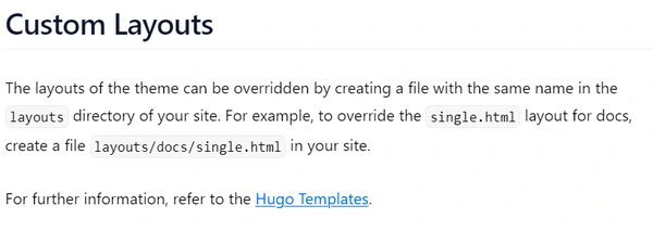 So we tried by copying the code from Hextra’s Github page and creating a new file and altering the code within the single file by adding th HTML code lines for the library’s from P5. But it did not overwrite it’s file and nothing changed on my site. We tried different things, honestly I was a bit lost here but Niels figured out a way to make it work by creating a new file in layouts -> partials -> custom -> head-end.html Here I pasted the custom HTML.
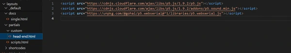
In the markdown page I added:
<script>

The javascript code

</script>
I changed the canvas size to a size that fits withing the page of the website. And it works!
 I learned that working withing these theme’s has the downside that doing custom stuff is a big hard. I could not have figure this out on my own.
The fun stuff!
Now try it out yourself by clicking (every click creates a new square in a random color and size) in the grey box below the stripe and drag your mouse to create a funky visual!