Week 13
Embedded Networking and Communications
| group assignments | — |
|---|---|
| Send a message between two projects | |
| Document your work to the group work page and reflect on your individual page what you learned |
| individual assignments | — |
|---|---|
| Design, build and connect wired or wireless node(s) with network or bus addresses and a local interface |
Organizing
This week I want to focus on the final project and work on the communication between the input pillow and the nightlight. I unknowingly worked with I2C communication a tiny bit hooking op an OLED screen during output devices Ideally I like it to work wireless so you can take the pillow with you easily. since I would also like the pillow to have a battery instead of a wires I think bluetooth low energy will be a good connection protocol for this project. I hope to have the input step response pillow put on the steppermotor form the night light. So this week I will also work on creating the PCB for the steppermotor the neopixels will be on the same board but I will design a module for it later.
Notes from Neil’s lecture
Why do we want multiple things communicating together?
- parallelism, each sensor has one processor
- modularity, easy to switch modules
- interference, powersuplies ripples.
We do not only use communicating to cover distance we also use it for system processor
wired networks
- asynchronous
- There are a series of nodes on the network
- They are in a bus and receive and transmit data can go out in multiple boards. the ID of the component is inside the component.
- hops
- can take a longer time to send and read data
- works by counts hops
- Al the components are the same, it counts the hops to know witch it needs to talk to.
- use else if: (cmd == ‘a’) to assign your address
- counter: gets to the end and reports back: there are 3 nodes in the bus.
- Broad hop (hybrid)
- broadcast line to assign addresses. Sends the message back using hops.
- The host can broadcast the message and use the path to do something.
Attiny 412 serial bus Ardian example
- Synchronous serial
- SPI
- Serial data in Serial data out, Select who you talk to CS and clock SCK
- I2C (wire in arduino) sample I2C Adrian Example you do need to preassign the addresses to them
Note: Asynchronous is non-blocking, which means it will send multiple requests at the same time. Synchronous is blocking — it will only send one request at a time and wait for that request to be answered, more information about it here
New kid on the blok:
- I3C, more information about it here In short it’s an upgrade of the I2C with greater speeds and more energy-efficient operations. In other words less power is needed to do more.
ATP is designed to work without clock
- one wire is for the bit: low or high.
- it needs 6 wires, 4 for signals, 1 gnd, 1 power
USB ethernet widely used for fast networks
radios
single chip powerful processor antenna connector and the radios on board 2.4 gHz it knows how to do wifi and bluetooth good chip to work with is the ESP32C3 Xiao, if you want to use the RP2040, the pico W RP2024 has bluetooth and wifi.
blueart Uart over bluetooth
Notes from Erwin’s lecture
Networking and communication is all about getting data from here to there and back again There are different ways of connecting stuff
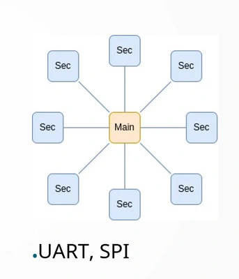
- Star topology, 1:1 connection each sensor talks to one device. Addressing is done by choosing which pin you will use to talk to which device
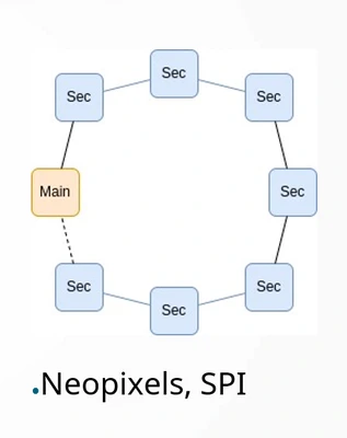
- Ring topology: It’s a chain in the shape of a ring such as neopixels each sensor talk so the next one in the ring.
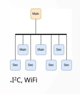
- Bus topology:
connect all the communications lines together and this one big node that is communicating with the main
Wifi and SPI are bus topologys
Serial communication:
- UART synchronize to the data signal. Within Arduino IDE: 9600,8,n,1
- 9600 = baud
- 8 =data
- n = no parity (checks if their is an error)
- 1 = one stop
So it will starts with one bit, reads 7 bits, checks with parity spots two stop bits
- The RS485: helps prevent a lot of interference because you are working with lots of motors for example multiple microcontrollers on the same bus. So they can talk to each other or letting your computer talk to your microcontroller.
SPI
- used for flash memory, SD cards and displays
- Sends a lot of data very fast, it uses chip select to specify with chip it’s going to talk to
- the chip-select pin needs to be enabled to know to with sensor it needs to talk
daisy-chaining meaning shifting output data through the chip to have minimum communications lines so less GPIO pins.
needs:
SS/CS: chip select
SCLK: clock
downside: you need a lot of pins to talk to a lot of receivers or you need a lot of programming for daisy chaining
I2C
Needs less wires then SPI it’s a more and more used protocol
It has 7 bit address mostly fixed
To gain more IO pins: IO expender for I2C : PCA9555
All the data and clock lines are wired together, io expender has an address
Side note:
- Bus pull-up/down, SPI: 10k Ohm pull down, I2C: 4k Ohm pull up
OSI model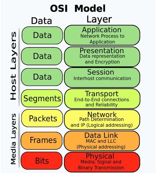 All the layers of devices communicating. The following layers at the start and end of the module have gained new possibility’s:
- physical layer - air, wire, sound
- application layer - what ever you plan to do with it However everything between these layers using the TCP-CP like the internet is still the same and hasn’t changed in quit a long time.
Group assignment
UART communication with arduino’s
Leo and Edwin will work on a MIDI communication between their projects since they experienced with this topic. Joe, Joany and me are beginners and will start working with arduino and UART for the first communication. The UART protocol uses the rx and tx pins and a common ground.
After this Joe and I tried to use bluetooth Low Energie to communicate wireless. Joe documented the bluetooth connection and I did the UART:
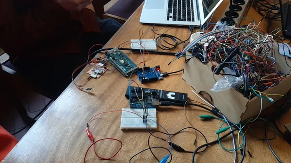
For this experiment we used the following:
Arduino Duemilanove
Arduino Leonardo
Potentiometer
breadboard
LED
220 Ohm resistor for LED
wires
We started working with the example code provided by Erwin, as Henk suggested. Putting the LED on pin 3 via the resistor to the ground and using a potmeter, which we had to figure out a bit to connect properly. And a sample potmeter code: potmeter to merge in the final code.
Sample code potmeter
/*
 * Created by ArduinoGetStarted.com
 *
 * This example code is in the public domain
 *
 * Tutorial page: https://arduinogetstarted.com/tutorials/arduino-potentiometer
 */

float floatMap(float x, float in_min, float in_max, float out_min, float out_max) {
  return (x - in_min) * (out_max - out_min) / (in_max - in_min) + out_min;
}

// the setup routine runs once when you press reset:
void setup() {
  // initialize serial communication at 9600 bits per second:
  Serial.begin(9600);
}

// the loop routine runs over and over again forever:
void loop() {
  // read the input on analog pin A0:
  int analogValue = analogRead(A0);
  // Rescale to potentiometer's voltage (from 0V to 5V):
  float voltage = floatMap(analogValue, 0, 1023, 0, 5);

  // print out the value you read:
  Serial.print("Analog: ");
  Serial.print(analogValue);
  Serial.print(", Voltage: ");
  Serial.println(voltage);
  delay(1000);
}- I worked with the Duemilanove and Joe with the Leonardo but we could not send the code.
- When we want to upload the code on my computer it keeps unplugging the USB cable when turning the potmeter. We think there is something wrong with the breadboard so we switch it, it’s not solving the issue. We try another computer, same issue. We think it’s the potmeter which we then figured out is broken. The unplugging problem is gone but still no success in getting the boards to communicate.
- Then Henk noticed the code is using Wire.h which it used for I2C communication so it’s the wrong sample code. He found a new sample for UART online.
We combined this code to include the LED and potmeter for the sender and receiver.
This is the code for the sender:
//Sender Code
int potValue = 0;
char str[4];
#define PIN_LED       3

void setup() {
 pinMode(PIN_LED, OUTPUT);
 Serial.begin(9600);
}

void loop() {
 potValue = analogRead(A0);
 potValue = map(potValue, 0, 1023, 0, 255);

 int value = potValue; //this would be much more exciting if it was a sensor value

 itoa(value, str, 10); //Turn value into a character array
 Serial.write(str, 4);

 analogWrite(PIN_LED, potValue);
}

// Wire.beginTransmission(NODE_ADDRESS);  Wire.write(potValue); Wire.endTransmission();
And for the receiver:
//Receiver Code

#define PIN_LED 3
char str[4];
byte rcvData = 31;

void setup() {
  pinMode(PIN_LED, OUTPUT);
  Serial.begin(9600);
  Serial1.begin(9600);
}

void loop() {
  analogWrite(PIN_LED, rcvData);
  int i=0;

  if (Serial1.available()) {
    delay(100); //allows all serial sent to be received together
    while(Serial1.available() && i<4) {
      str[i++] = Serial1.read();
    }
    str[i++]='\0';
  }

  if(i>0) {
    Serial.println(str,4);
  }
}- The (Arduino Duemilanove) compiled but it’s reading wierd values in the monitor. When you turn you do see a change in numbers en the LED starts fading. After a closer look we see that the char is loosing numbers but it’s actually reading the pot value’s, on the website we found the problem in the following sentence:
There is one flaw with this program as it is now. It results in only a character array, so if the integers were desired, they are lost without further work on the data.
We think this is the problem why it’s losing numbers, it goes from 3 to 2 to 1 integer while reading the potentiometer value.
So we will try a new sample using UART: new sample for a clearer read. This sample uses buttons and you can read the low and high state on the other board. It only managed to read one way but not the other but I documented this poorly so I have no pics or vid of it. Joe and I are still not super happy about our results but we decide to dive in to wireless connection using BLE as the next step that Joe documented.
Lessons:
- take some time finding the good example don’t rush into it.
- don’t trust hardware
Board design
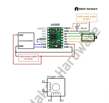
So this week I want to work in the spirit of the final project and I decide to start the week creating a new board for driving the stepper motor with power supply and break out for the neo pixels, that I will design modular so less things can go wrong.
I start by taking a look at the schematic I put on paper with the help of Erwin last week. and gathering my components.
BOM:
- Capacitor 100uF1
- StepStick A4988
- JST Conn_ P4,2.54mm
- Conn_01x06, PinHeader_1x06_P2.54mm_Horizontal_SMD
- 2 x Conn_01x06, PinSocket_1x07_P2.54mm_Vertical_THT
- 2 x Conn_01x07, PinSocket_1x07_P2.54mm_Vertical_THT
- Barrel_Jack_Switch_Pin3Ring
- XIAO-ESP32C3_SocketSMD
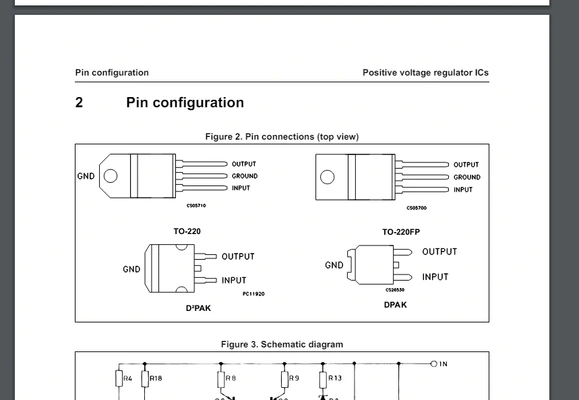
- L7805ACP Voltage regulator
- NEMA 17 Stepper motor SY42TH38-1684A
- switching adapter power supply output 12V, 2A DC
I looked in to the data sheet of (for me) new components:
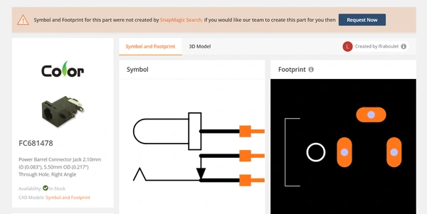
 I start designing the board, I had to import footprints from SnapEda for the voltage regulator and the Barrel Jack connector for the power supply.
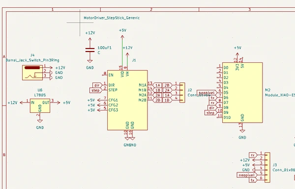
this is the pcb design
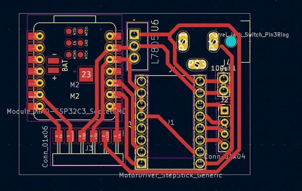
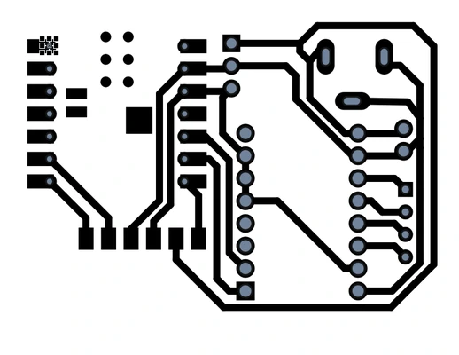
When exporting to svg file I had to extend the traces for the pads of the Jack plug because I could not connect the traces within KiCAD, something went wrong importing the footprint I think.. But I didn’t look into it and went for this solution instead:

 I also had so make the drill holes I did it with the auto fill tool in Corel draw and created a new layer. So my file had 3 layers at the end. 1 with the traces 1 with the holes and 1 with the edge cut.
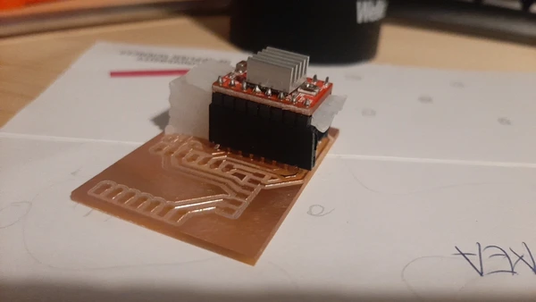
 After I milled the design I see I could have better make the through whole components to be mounted on the back because it’s now very hard to solder the pins from the top.
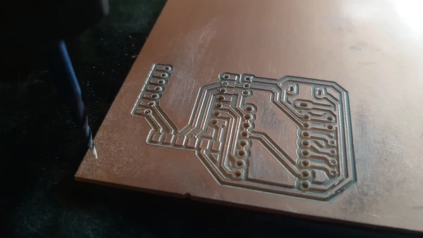
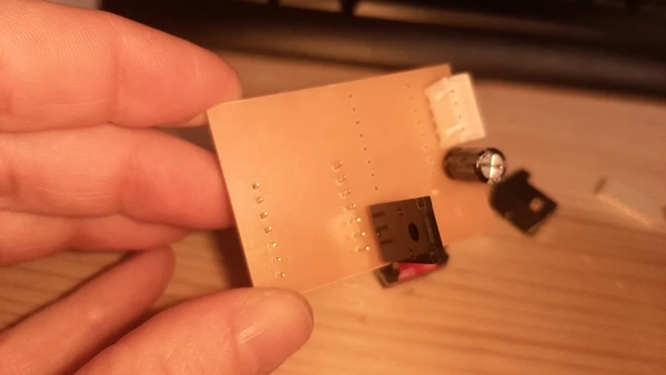 I managed to solder the pins from the top with a small spaces made from silicon from last weeks molding and casting leftover. But it took me a long time!
Testing the board
When al the components are in place I start uploading the code that had worked before. But now I had troubles getting it to work, so I got my multimeter and started with testing if the voltage regulator worked. I measured 12V were it should be 12 and 5V were it should be 5, to power the ESP32 but it did not turn on the ESP cause there was no led indicating.
After questioning a lot of things I went to mattermost chat for help.

I sended a picture of the sematic and here I now see that I put the 5V to the 3V pin.. What a stupid silly mistake!
Leo later took the time to explain to me the structure of the PCB design of the Xiao board, in the board there is also a voltage regulator to convert the 5V to 3V.
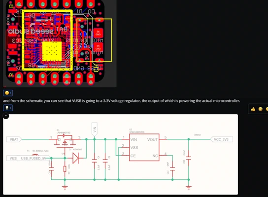 You can also see the USB power connected to the 5V pin.
But at least I know what’s wrong. I solder some new wires and try it out again. I see nothing happening. I decide to check if the esp32 is still working so I connect it to my laptop, still not so I fried it.. Sadly. I switch the ESP and the stepper driver and upload the code again. Put in the external powerfully and the stepper motor is moving! It’s finally working :D After a few tries with the code it stopped again. I measured more pins and I fixed a pour soldered pin from the voltage regulator. This was the problem and I’m now left with a functional board.
You can also see the USB power connected to the 5V pin.
But at least I know what’s wrong. I solder some new wires and try it out again. I see nothing happening. I decide to check if the esp32 is still working so I connect it to my laptop, still not so I fried it.. Sadly. I switch the ESP and the stepper driver and upload the code again. Put in the external powerfully and the stepper motor is moving! It’s finally working :D After a few tries with the code it stopped again. I measured more pins and I fixed a pour soldered pin from the voltage regulator. This was the problem and I’m now left with a functional board.
BLE getting started
Next step is to get the BLE send something more that the text sample Joe and I worked on. I take a loot at Michelle’s documentation because I know she did something similar.
I start an confusing and messy process honestly don’t know how to type out what i’ve been doing. I do now that a lot of it won’t be helpful for other people but let’s start with the things that might. Because while reading and trying different codes I picked up on a few things I wished I knew before:
- If you continuously have upload exit status 2 failures in the Arduino IDE working with the Xiao ESP32C3 you need to hold the b(bootload) button pressed before plugging the board in your pc and this error will go away. So for me it will now only upload in bootload mode but I have made peace with it. After uploading you need to press r to reset the board and start the newly uploaded program.
Bluetooth Low Energie is a wireless connection between two devices that uses less power than normal Bluetooth. It uses point to point communication for continuously connection, BLE is used for small amounts of data
bluetooth knows 2 states: onconnect and ondisconnect
generate or use a sample UUID, Each service, characteristic and descriptor have an UUID (Universally Unique Identifier). An UUID is a unique 128-bit (16 bytes) number. should be the same for the sender and receiver so they can communicate.
notification: This function is used for when the server notifies things of importance, like data changing and pushes this to the client. This is different then a client asking for data every now and then. I want to use it for the sensor data so it only pushes data when it’s changing.
a client needs to declare that it’s interested in the changes it does it with the BLE2909 indication when the pCharacteristic value has changes.
Server : main board not difficult with power can be battery’s, Client: difficult with power batteries (tip from Edwin)
The steps of creating the BLE server are:
- Create a BLE Server
- Create a BLE Service
- Create a BLE Characteristic on the Service
- Create a BLE Descriptor on the characteristic
- Start the service.
- Start advertising.
BLE sensor data (fail)
So My goal was to merge the code I used during input devices to read the step response from the pillow and send this data using the BLE example of the “hello world” text that worked during the group assignment. Besides this code below I tried many other examples on the internet and from Michelle’s page trying to merge it together with the step response code and asking help from chatgpt. To many messy codes to share with you and all of no help so after hours of struggling I went back to what had worked and tried once more:
#include <BLEDevice.h>
#include <BLEUtils.h>
#include <BLEServer.h>
// See the following for generating UUIDs:
// https://www.uuidgenerator.net/
#define SERVICE_UUID "4fafc201-1fb5-459e-8fcc-c5c9c331914b"
#define CHARACTERISTIC_UUID "beb5483e-36e1-4688-b7f5-ea07361b26a8"
/* BLEServer *pServer = BLEDevice::createServer();
BLEService *pService = pServer->createService(SERVICE_UUID);
BLECharacteristic *pCharacteristic = pService->createCharacteristic(
CHARACTERISTIC_UUID,
BLECharacteristic::PROPERTY_READ |
BLECharacteristic::PROPERTY_WRITE
); */
BLEServer *pServer;
BLEService *pService;
BLECharacteristic *pCharacteristic;
long result; //variable for the result of the tx_rx measurement.
int analog_pin = A0; // GPIO 27 of the XIA0 RP2040 or ESP32-C3 pin A1
int tx_pin = D1; // GPIO 28 of the XIAO RP2040 or ESP32-C3 pin D2
void setup()
{
pinMode(tx_pin,OUTPUT); //Pin 2 provides the voltage step
Serial.begin(115200);
Serial.println("Starting BLE Server!");
BLEDevice::init("ESP32-BLE-Server");
pServer = BLEDevice::createServer();
pService = pServer->createService(SERVICE_UUID);
pCharacteristic = pService->createCharacteristic(
CHARACTERISTIC_UUID,
BLECharacteristic::PROPERTY_READ |
BLECharacteristic::PROPERTY_WRITE
);
/* BLEServer *pServer = BLEDevice::createServer();
BLEService *pService = pServer->createService(SERVICE_UUID);
BLECharacteristic *pCharacteristic = pService->createCharacteristic(
CHARACTERISTIC_UUID,
BLECharacteristic::PROPERTY_READ |
BLECharacteristic::PROPERTY_WRITE
);*/
pCharacteristic->setValue("Hello, World!");
pService->start();
//BLEAdvertising *pAdvertising = pServer->getAdvertising();
BLEAdvertising *pAdvertising = BLEDevice::getAdvertising();
pAdvertising->addServiceUUID(SERVICE_UUID);
pAdvertising->setScanResponse(true);
pAdvertising->setMinPreferred(0x06); // functions that help with iPhone connections issue
pAdvertising->setMinPreferred(0x12);
BLEDevice::startAdvertising();
//pAdvertising->start();
Serial.println("Characteristic defined! Now you can read it in the Client!");
long tx_rx() { //Function to execute rx_tx algorithm and return a value
//that depends on coupling of two electrodes.
//Value returned is a long integer.
int read_high;
int read_low;
int diff;
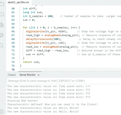
long int sum;
int N_samples = 100; //Number of samples to take. Larger number slows it down, but reduces scatter.
sum = 0;
for (int i = 0; i < N_samples; i++){
digitalWrite(tx_pin,HIGH); //Step the voltage high on conductor 1.
read_high = analogRead(analog_pin); //Measure response of conductor 2.
delayMicroseconds(100); //Delay to reach steady state.
digitalWrite(tx_pin,LOW); //Step the voltage to zero on conductor 1.
read_low = analogRead(analog_pin); //Measure response of conductor 2.
diff = read_high - read_low; //desired answer is the difference between high and low.
sum += diff; //Sums up N_samples of these measurements.
}
return sum;
}
void loop()
{
result = tx_rx();
result = map(result, 1000, 50000, 0, 1024);
std::string value = pCharacteristic->getValue();
Serial.print("The new characteristic value is: ");
Serial.println(value.c_str());
Serial.println(result());
delay(2000);
}I got the following upload error: Compilation error: a function-definition is not allowed here before ‘{’ token
I asked chat GPT what it means and it said the following:
It seems like you've attempted to define the tx_rx() function within the setup() function, which isn't allowed in C++. The tx_rx() function should be defined outside of any other function, either before or after the setup() and loop() functions.
Doubtful if this is helping me at this point I decide to take a step back from the pillow sensor step response value and I’m going to try something more simple.
BLE send button state (success)
I’m going to try to send a button state instead so pressed or not pressed.
To do this I first try to merge the code for reading a button from a previous project of mine were I used the button to turn on a neopixel in week 8 electronics design and the sample BLE that worked sending hello world. From this page I can upload the code but it’s showing nothing no error but also no communication -> An empty serial monitor again… so i asked chatGTP to: check my code:
const int buttonPin = D6;  // button pin ESP32-C3 pin D6
int buttonState = 0;       // initial state of the button

#include <BLEDevice.h>
#include <BLEUtils.h>
#include <BLEServer.h>

// See the following for generating UUIDs:
// https://www.uuidgenerator.net/

#define SERVICE_UUID        "4fafc201-1fb5-459e-8fcc-c5c9c331914b"
#define CHARACTERISTIC_UUID "beb5483e-36e1-4688-b7f5-ea07361b26a8"

/* BLEServer *pServer = BLEDevice::createServer();
BLEService *pService = pServer->createService(SERVICE_UUID);
BLECharacteristic *pCharacteristic = pService->createCharacteristic(
                                         CHARACTERISTIC_UUID,
                                         BLECharacteristic::PROPERTY_READ |
                                         BLECharacteristic::PROPERTY_WRITE
                                       ); */

BLEServer *pServer;
BLEService *pService;
BLECharacteristic *pCharacteristic;


void setup()
{
   pinMode(buttonPin, INPUT);
   Serial.begin(115200);
  Serial.println("Starting BLE Server!");

  BLEDevice::init("ESP32-BLE-Server");
  pServer = BLEDevice::createServer();
  pService = pServer->createService(SERVICE_UUID);
  pCharacteristic = pService->createCharacteristic(
                                         CHARACTERISTIC_UUID,
                                         BLECharacteristic::PROPERTY_READ |
                                         BLECharacteristic::PROPERTY_WRITE
                                       );


  /* BLEServer *pServer = BLEDevice::createServer();
  BLEService *pService = pServer->createService(SERVICE_UUID);
  BLECharacteristic *pCharacteristic = pService->createCharacteristic(
                                         CHARACTERISTIC_UUID,
                                         BLECharacteristic::PROPERTY_READ |
                                         BLECharacteristic::PROPERTY_WRITE
                                       );*/

  pCharacteristic->setValue("Hello, World!");
  pService->start();
  //BLEAdvertising *pAdvertising = pServer->getAdvertising();
  BLEAdvertising *pAdvertising = BLEDevice::getAdvertising();
  pAdvertising->addServiceUUID(SERVICE_UUID);
  pAdvertising->setScanResponse(true);
  pAdvertising->setMinPreferred(0x06);  // functions that help with iPhone connections issue
  pAdvertising->setMinPreferred(0x12);
  BLEDevice::startAdvertising();
  //pAdvertising->start();
  Serial.println("Characteristic defined! Now you can read it in the Client!");
}

void loop()

{

  buttonState = digitalRead(buttonPin); // Read the state of the button
  if (buttonState == HIGH) { // if the button is pressed
  Serial.print("button is pressed ");
  } else {

  Serial.print("button is not pressed ");
  }
  std::string value = pCharacteristic->getValue();
  Serial.print("The new characteristic value is: ");
  Serial.println(value.c_str());
  delay(2000);
}
ChatGPT is telling me the following:
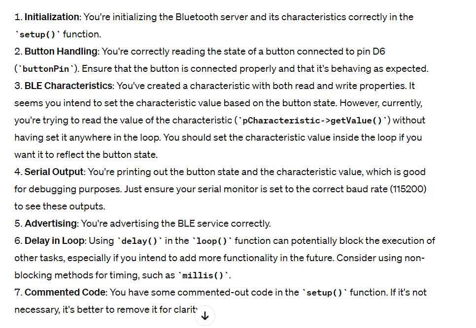 So i’m not correctly reading the Value with get data and the characteristic value should be inside the loop. It gives me an alternative:
void loop() {
  buttonState = digitalRead(buttonPin); // Read the state of the button
  if (buttonState == HIGH) { // if the button is pressed
    pCharacteristic->setValue("Button Pressed");
    Serial.println("Button is pressed");
  } else {
    pCharacteristic->setValue("Button Not Pressed");
    Serial.println("Button is not pressed");
  }
  pCharacteristic->notify(); // Notify clients about the changed value
  delay(1000); // Delay for stability
}
So I merge this code in my previous example and it uploads but I can’t see anything in the monitor still.
Very frustrating. At this point I’m really stuck and I do not know what to do anymore. Continue with BLE or changing to something else. I write a post on mattermost hoping someone has time to help me out, got great advise from Leo in the evening and I made a meme out of it:
 . But in the afternoon, I called Bert a volunteer from Fablab Arnhem, to help me a bit. I explained to him what I have been doing and all the errors that occurred. He tells me that if the text is send correctly in the sample code I should also be able so send the button state so same advise don’t give up. He said something like if I store the button value in a variable and change it for the text it should always work. While we talk about it I realize the altered code from chatGPT is sending two things now. When the button is pressed and when it’s not, and the sample code is only sending one. This gives me a bit of hope I can fix this. I decide to give it one more try.
I use chat gpt to help me generate the variable to store the button state and I get it to work.
I used the following prompt:
recreate the code but store the button pressed value inside a variable so it will only send 1 value via bluetooth
I check the code below and see it generated a boolean so false or true to check is the button is pressed. I also see the notify i red about that will only send if something is changing. I upload the code and see the monitors working! When I press the button I can read on the other laptop (i’m using two) that it received data. Hallelujah i’m really happy I was able to do a bit more than “Hello world”.
The codes
Server
#include <BLEDevice.h>
#include <BLEUtils.h>
#include <BLEServer.h>

const int buttonPin = D6;  // Button pin, ESP32-C3 pin D6
int buttonState = 0;       // Initial state of the button
int lastButtonState = LOW; // Previous state of the button
bool stateChanged = false; // Flag to track if the button state has changed

#define SERVICE_UUID        "4fafc201-1fb5-459e-8fcc-c5c9c331914b"
#define CHARACTERISTIC_UUID "beb5483e-36e1-4688-b7f5-ea07361b26a8"

BLEServer *pServer;
BLEService *pService;
BLECharacteristic *pCharacteristic;

void setup() {
  pinMode(buttonPin, INPUT);
  Serial.begin(115200);
  Serial.println("Starting BLE Server!");

  BLEDevice::init("ESP32-BLE-Server");
  pServer = BLEDevice::createServer();
  pService = pServer->createService(SERVICE_UUID);
  pCharacteristic = pService->createCharacteristic(
                                         CHARACTERISTIC_UUID,
                                         BLECharacteristic::PROPERTY_READ |
                                         BLECharacteristic::PROPERTY_NOTIFY
                                       );
  pCharacteristic->setValue("Button Not Pressed");
  pService->start();

  BLEAdvertising *pAdvertising = BLEDevice::getAdvertising();
  pAdvertising->addServiceUUID(SERVICE_UUID);
  pAdvertising->setScanResponse(true);
  pAdvertising->setMinPreferred(0x06);  // Functions that help with iPhone connections issue
  pAdvertising->setMinPreferred(0x12);
  BLEDevice::startAdvertising();
}

void loop() {
  buttonState = digitalRead(buttonPin); // Read the state of the button

  if (buttonState != lastButtonState) { // If button state has changed
    stateChanged = true;
    lastButtonState = buttonState; // Update lastButtonState
  }

  if (stateChanged) {
    if (buttonState == HIGH) { // If the button is pressed
      pCharacteristic->setValue("Button Pressed");
      Serial.println("Button is pressed");
    } else {
      pCharacteristic->setValue("Button Not Pressed");
      Serial.println("Button is not pressed");
    }

    pCharacteristic->notify(); // Notify clients about the changed value
    stateChanged = false; // Reset stateChanged flag
  }

  delay(100); // Add a small delay to debounce the button and prevent flickering
}
Client
#include "BLEDevice.h"
/* Specify the Service UUID of Server */
static BLEUUID serviceUUID("4fafc201-1fb5-459e-8fcc-c5c9c331914b");
/* Specify the Characteristic UUID of Server */
static BLEUUID charUUID("beb5483e-36e1-4688-b7f5-ea07361b26a8");
static boolean doConnect = false;
static boolean connected = false;
static boolean doScan = false;
static BLERemoteCharacteristic* pRemoteCharacteristic;
static BLEAdvertisedDevice* myDevice;
static void notifyCallback(BLERemoteCharacteristic* pBLERemoteCharacteristic,
uint8_t* pData, size_t length, bool isNotify)
{
Serial.print("Notify callback for characteristic ");
Serial.print(pBLERemoteCharacteristic->getUUID().toString().c_str());
Serial.print(" of data length ");
Serial.println(length);
Serial.print("data: ");
Serial.println((char*)pData);
}
class MyClientCallback : public BLEClientCallbacks
{
void onConnect(BLEClient* pclient)
{
}
void onDisconnect(BLEClient* pclient)
{
connected = false;
Serial.println("onDisconnect");
}
};
/* Start connection to the BLE Server */
bool connectToServer()
{
Serial.print("Forming a connection to ");
Serial.println(myDevice->getAddress().toString().c_str());
BLEClient* pClient = BLEDevice::createClient();
Serial.println(" - Created client");
pClient->setClientCallbacks(new MyClientCallback());
/* Connect to the remote BLE Server */
pClient->connect(myDevice); // if you pass BLEAdvertisedDevice instead of address, it will be recognized type of peer device address (public or private)
Serial.println(" - Connected to server");
/* Obtain a reference to the service we are after in the remote BLE server */
BLERemoteService* pRemoteService = pClient->getService(serviceUUID);
if (pRemoteService == nullptr)
{
Serial.print("Failed to find our service UUID: ");
Serial.println(serviceUUID.toString().c_str());
pClient->disconnect();
return false;
}
Serial.println(" - Found our service");
/* Obtain a reference to the characteristic in the service of the remote BLE server */
pRemoteCharacteristic = pRemoteService->getCharacteristic(charUUID);
if (pRemoteCharacteristic == nullptr)
{
Serial.print("Failed to find our characteristic UUID: ");
Serial.println(charUUID.toString().c_str());
pClient->disconnect();
return false;
}
Serial.println(" - Found our characteristic");
/* Read the value of the characteristic */
/* Initial value is 'Hello, World!' */
if(pRemoteCharacteristic->canRead())
{
std::string value = pRemoteCharacteristic->readValue();
Serial.print("The characteristic value was: ");
Serial.println(value.c_str());
}
if(pRemoteCharacteristic->canNotify())
{
pRemoteCharacteristic->registerForNotify(notifyCallback);
}
connected = true;
return true;
}
/* Scan for BLE servers and find the first one that advertises the service we are looking for. */
class MyAdvertisedDeviceCallbacks: public BLEAdvertisedDeviceCallbacks
{
/* Called for each advertising BLE server. */
void onResult(BLEAdvertisedDevice advertisedDevice)
{
Serial.print("BLE Advertised Device found: ");
Serial.println(advertisedDevice.toString().c_str());
/* We have found a device, let us now see if it contains the service we are looking for. */
if (advertisedDevice.haveServiceUUID() && advertisedDevice.isAdvertisingService(serviceUUID))
{
BLEDevice::getScan()->stop();
myDevice = new BLEAdvertisedDevice(advertisedDevice);
doConnect = true;
doScan = true;
}
}
};
void setup()
{
Serial.begin(115200);
Serial.println("Starting Arduino BLE Client application...");
BLEDevice::init("ESP32-BLE-Client");
/* Retrieve a Scanner and set the callback we want to use to be informed when we
have detected a new device. Specify that we want active scanning and start the
scan to run for 5 seconds. */
BLEScan* pBLEScan = BLEDevice::getScan();
pBLEScan->setAdvertisedDeviceCallbacks(new MyAdvertisedDeviceCallbacks());
pBLEScan->setInterval(1349);
pBLEScan->setWindow(449);
pBLEScan->setActiveScan(true);
pBLEScan->start(5, false);
}
void loop()
{
/* If the flag "doConnect" is true, then we have scanned for and found the desired
BLE Server with which we wish to connect. Now we connect to it. Once we are
connected we set the connected flag to be true. */
if (doConnect == true)
{
if (connectToServer())
{
Serial.println("We are now connected to the BLE Server.");
}
else
{
Serial.println("We have failed to connect to the server; there is nothin more we will do.");
}
doConnect = false;
}
/* If we are connected to a peer BLE Server, update the characteristic each time we are reached
with the current time since boot */
if (connected)
{
String newValue = "Time since boot: " + String(millis()/2000);
Serial.println("Setting new characteristic value to \"" + newValue + "\"");
/* Set the characteristic's value to be the array of bytes that is actually a string */
pRemoteCharacteristic->writeValue(newValue.c_str(), newValue.length());
/* You can see this value updated in the Server's Characteristic */
}
else if(doScan)
{
BLEDevice::getScan()->start(0); // this is just example to start scan after disconnect, most likely there is better way to do it in arduino
}
delay(2000); /* Delay a second between loops */
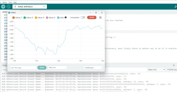
}BLE sensor data success!
Thursday we gathered at Waag and I was looking forward getting some help with why I could not manage to read the sensor data. Michelle took a quick look at the code and already noticed some basic mistakes. My code was missing a bracket somewhere I put a part of the stepresponse sample code inside the void loop instead of the void setup. Also the way the code want to send and receive the data looks a bit strange since it’s working with the * pRemoteCharacteristic->writeValue(newValue.c_str(), newValue.length());* write value is not so commonly used. After the introduction from Bas for the new week he took quite some time to help me figuring out this BLE. It was really nice of him. He noticed I should make my code more neat and document the language so the colors will appear. He showed me how to do it. Together we went through the code to try to understand it better.
Biggest mistakes that I made:
- unorganized messy code missing brackets and having part’s of the step response code inside the void setup that should be before the void setup. The problems kept adding up making it invisible for me to see my mistakes.
- not understanding their are differences between sending data.
You can send data as a:
- booleans (true or false)
- integers (whole numbers)
- floats (decimal numbres (more precise))
- characters (number or symbol stored in a byte) Each character is represented by a specific number according to a coding scheme like ASCII or Unicode.

Characters are easy to send between 0 and 255 because they exits of one byte in the ASCII system.
With the new code we were able to establish a BLE connection and send the sensor data.
Especially the following lines of code are important and I didn’t understand them before.
For sending data:
String sensorValueString(result);Converts the mapped result to a string (sequence of characters between quotes, used for writing text in coding). This is necessary because the BLE (pCharacteristic) expects a string value to be send and received. Sending characters is easier than sending other types of data.pCharacteristic->setValue(sensorValueString.c_str());Updates the BLE characteristic with the new string value. This code also transforms the String object (arduino) into a string (character array C-style) which is needed for the setValue function.
Here you can find the whole code for the pillow.
the pillow
//Sensor sending device
#include <BLEDevice.h>
#include <BLEUtils.h>
#include <BLEServer.h>
const int buttonPin = D6;   // Button pin, ESP32-C3 pin D6
int buttonState = 0;        // Initial state of the button
int lastButtonState = LOW;  // Previous state of the button
bool stateChanged = false;  // Flag to track if the button state has changed
uint64_t prevMillis = 0;

#define SERVICE_UUID "4fafc201-1fb5-459e-8fcc-c5c9c331914b"
#define CHARACTERISTIC_UUID "beb5483e-36e1-4688-b7f5-ea07361b26a8"


BLEServer *pServer;
BLEService *pService;
BLECharacteristic *pCharacteristic;

long result;          //variable for the result of the tx_rx measurement.
int analog_pin = A0;  //  GPIO 27 of the XIA0 RP2040 or ESP32-C3 pin A1
int tx_pin = D1;      //     GPIO 28 of the XIAO RP2040 or ESP32-C3 pin D2

long tx_rx() {  //Function to execute rx_tx algorithm and return a value
                //that depends on coupling of two electrodes.
                //Value returned is a long integer.
  int read_high;
  int read_low;
  int diff;
  long int sum;
  int N_samples = 100;  //Number of samples to take.  Larger number slows it down, but reduces scatter.

  sum = 0;

  for (int i = 0; i < N_samples; i++) {
    digitalWrite(tx_pin, HIGH);          //Step the voltage high on conductor 1.
    read_high = analogRead(analog_pin);  //Measure response of conductor 2.
    delayMicroseconds(100);              //Delay to reach steady state.
    digitalWrite(tx_pin, LOW);           //Step the voltage to zero on conductor 1.
    read_low = analogRead(analog_pin);   //Measure response of conductor 2.
    diff = read_high - read_low;         //desired answer is the difference between high and low.
    sum += diff;                         //Sums up N_samples of these measurements.
  }
  return sum;
}  //End of tx_rx function.

void setup() {
  pinMode(buttonPin, INPUT);
  pinMode(tx_pin, OUTPUT);  //Pin 2 provides the voltage step

  Serial.begin(115200);
  Serial.println("Starting BLE Server!");


  BLEDevice::init("ESP32-BLE-Server");
  pServer = BLEDevice::createServer();
  pService = pServer->createService(SERVICE_UUID);
  pCharacteristic = pService->createCharacteristic(
    CHARACTERISTIC_UUID,
    BLECharacteristic::PROPERTY_READ | BLECharacteristic::PROPERTY_NOTIFY);
  pCharacteristic->setValue("Button Not Pressed");
  pService->start();


  BLEAdvertising *pAdvertising = BLEDevice::getAdvertising();
  pAdvertising->addServiceUUID(SERVICE_UUID);
  pAdvertising->setScanResponse(true);
  pAdvertising->setMinPreferred(0x06);  // Functions that help with iPhone connections issue
  pAdvertising->setMinPreferred(0x12);
  BLEDevice::startAdvertising();
}


void loop() {

  buttonState = digitalRead(buttonPin);  // Read the state of the button
  result = tx_rx();
  result = map(result, 1000, 50000, 0, 1024);  //I recommend mapping the values of the two copper plates, it will depend on their size


  if (buttonState != lastButtonState) {  // If button state has changed
    stateChanged = true;
    lastButtonState = buttonState;  // Update lastButtonState
  }

  String sensorValueString(result);

   //if (buttonState == HIGH) {  // If the button is pressed
      pCharacteristic->setValue(sensorValueString.c_str());
      Serial.println(sensorValueString);
   // } else {
    //  pCharacteristic->setValue("Button Not Pressed");
   //   Serial.println("Button is not pressed");
 //   }


    pCharacteristic->notify();  // Notify clients about the changed value
  // stateChanged = false;       // Reset stateChanged flag
  //}

  //delay(100);  // Add a small delay to debounce the button and prevent flickering
}
For the nightlight (receiving code) I had help from bas with the following lines of code:
Serial.println((char*)pData);
  String sensorValueString(pData);
  int sensorValue = sensorValueString.toInt();
This code makes sure whenever the client receives a notification (change in the sended data) from the pillow ESP, is will convert the received data to a string and then to an integer.
the nightlight
#include "BLEDevice.h"

/* Specify the Service UUID of Server */
static BLEUUID serviceUUID("4fafc201-1fb5-459e-8fcc-c5c9c331914b");
/* Specify the Characteristic UUID of Server */
static BLEUUID charUUID("beb5483e-36e1-4688-b7f5-ea07361b26a8");

static boolean doConnect = false;
static boolean connected = false;
static boolean doScan = false;
static BLERemoteCharacteristic* pRemoteCharacteristic;
static BLEAdvertisedDevice* myDevice;

static void notifyCallback(BLERemoteCharacteristic* pBLERemoteCharacteristic,
                           uint8_t* pData, size_t length, bool isNotify) {
 // Serial.print("Notify callback for characteristic ");
 // Serial.print(pBLERemoteCharacteristic->getUUID().toString().c_str());
 /// Serial.print(" of data length ");
 // Serial.println(length);
// Serial.print("data: ");
  Serial.println((char*)pData);
  String sensorValueString(pData);
  int sensorValue = sensorValueString.toInt();
}

class MyClientCallback : public BLEClientCallbacks {
  void onConnect(BLEClient* pclient) {
  }

  void onDisconnect(BLEClient* pclient) {
    connected = false;
    Serial.println("onDisconnect");
  }
};

/* Start connection to the BLE Server */
bool connectToServer() {
  Serial.print("Forming a connection to ");
  Serial.println(myDevice->getAddress().toString().c_str());

  BLEClient* pClient = BLEDevice::createClient();
  Serial.println(" - Created client");

  pClient->setClientCallbacks(new MyClientCallback());

  /* Connect to the remote BLE Server */
  pClient->connect(myDevice);  // if you pass BLEAdvertisedDevice instead of address, it will be recognized type of peer device address (public or private)
  Serial.println(" - Connected to server");

  /* Obtain a reference to the service we are after in the remote BLE server */
  BLERemoteService* pRemoteService = pClient->getService(serviceUUID);
  if (pRemoteService == nullptr) {
    Serial.print("Failed to find our service UUID: ");
    Serial.println(serviceUUID.toString().c_str());
    pClient->disconnect();
    return false;
  }
  Serial.println(" - Found our service");


  /* Obtain a reference to the characteristic in the service of the remote BLE server */
  pRemoteCharacteristic = pRemoteService->getCharacteristic(charUUID);
  if (pRemoteCharacteristic == nullptr) {
    Serial.print("Failed to find our characteristic UUID: ");
    Serial.println(charUUID.toString().c_str());
    pClient->disconnect();
    return false;
  }
  Serial.println(" - Found our characteristic");

  /* Read the value of the characteristic */
  /* Initial value is 'Hello, World!' */
  if (pRemoteCharacteristic->canRead()) {
    std::string value = pRemoteCharacteristic->readValue();
    Serial.print("The characteristic value was: ");
    Serial.println(value.c_str());
  }

  if (pRemoteCharacteristic->canNotify()) {
    pRemoteCharacteristic->registerForNotify(notifyCallback);
  }

  connected = true;
  return true;
}
/* Scan for BLE servers and find the first one that advertises the service we are looking for. */
class MyAdvertisedDeviceCallbacks : public BLEAdvertisedDeviceCallbacks {
  /* Called for each advertising BLE server. */
  void onResult(BLEAdvertisedDevice advertisedDevice) {
    Serial.print("BLE Advertised Device found: ");
    Serial.println(advertisedDevice.toString().c_str());

    /* We have found a device, let us now see if it contains the service we are looking for. */
    if (advertisedDevice.haveServiceUUID() && advertisedDevice.isAdvertisingService(serviceUUID)) {
      BLEDevice::getScan()->stop();
      myDevice = new BLEAdvertisedDevice(advertisedDevice);
      doConnect = true;
      doScan = true;
    }
  }
};


void setup() {
  Serial.begin(115200);
  Serial.println("Starting Arduino BLE Client application...");
  BLEDevice::init("ESP32-BLE-Client");

  /* Retrieve a Scanner and set the callback we want to use to be informed when we
     have detected a new device.  Specify that we want active scanning and start the
     scan to run for 5 seconds. */
  BLEScan* pBLEScan = BLEDevice::getScan();
  pBLEScan->setAdvertisedDeviceCallbacks(new MyAdvertisedDeviceCallbacks());
  pBLEScan->setInterval(1349);
  pBLEScan->setWindow(449);
  pBLEScan->setActiveScan(true);
  pBLEScan->start(5, false);
}


void loop() {

  /* If the flag "doConnect" is true, then we have scanned for and found the desired
     BLE Server with which we wish to connect.  Now we connect to it.  Once we are
     connected we set the connected flag to be true. */
  if (doConnect == true) {
    if (connectToServer()) {
      Serial.println("We are now connected to the BLE Server.");
    } else {
      Serial.println("We have failed to connect to the server; there is nothin more we will do.");
    }
    doConnect = false;
  }

  /* If we are connected to a peer BLE Server, update the characteristic each time we are reached
     with the current time since boot */
  if (connected) {
    String newValue = "Time since boot: " + String(millis() / 2000);
  //  Serial.println("Setting new characteristic value to \"" + newValue + "\"");

    /* Set the characteristic's value to be the array of bytes that is actually a string */
    pRemoteCharacteristic->writeValue(newValue.c_str(), newValue.length());
    /* You can see this value updated in the Server's Characteristic */
  } else if (doScan) {
    BLEDevice::getScan()->start(0);  // this is just example to start scan after disconnect, most likely there is better way to do it in arduino
  }

  delay(2000); /* Delay a second between loops */
}
Reflection
This week was not the most fun week for me so I ended the week making a meme XD. I have a hard time working on coding and finding the focus and patient. I tried not be stuck in “I don’t know what I’m doing” to long because it demotivates me. Especially with the BLE I struggled! so I reached out for some help but I need some more. because I’m still very much wondering how this will ever communicate what I have in mind. I know I have to just keep trying, but the thing is, a lot of times I don’t know what to try. So looking forward getting some help with the BLE at Waag tomorrow!
This week I was able to get the stepstick driver to work and I made my PCB and fixed the problem with the board :D. However since I didn’t use the board in the communication exercise for this week, like I planned in the beginning, it’s a success non related to this weeks topic. But still I’m happy about it and I hope to still get wireless communication to turn on the motor based on the step response value soon. I did notice that I have more motivation and fun in the weeks that we made something physical like laser cutting and CNC working. With coding it’s harder for me to stay focussed and I know very little about it so that’s making it extra difficult I think.
My plan is to write down what I actually want this final project code to do on paper in steps to break it down and after this try to find good samples for it.
Update: getting help from Michelle and Bas helped me having a better understanding about the sending and receiving data types via BLE. I have to say the code it still a bit daunting but I’m beginning to understand a big part of the code can be ignored and left the same as the sample code. However the part about sending and receiving data is very important. And I need to work more clean and understandable otherwise it becomes furry and I can’t make sense of the code anymore. So I have to pay attention to brackets, tabs, colors, make good notes etc.
Update: I worked on a wireless communication via ESP-NOW after this week you can read about it here. I used this for my final project.