Week 11
Input Devices
| group assignments | — |
|---|---|
| Probe an input device(s)’s analog levels and digital signals | |
| Document your work on the group work page and reflect on your individual page what you learned |
| individual assignments | — |
|---|---|
| Measure something: add a sensor to a microcontroller board that you have designed and read it. |
Organizing
I have lots to learn this week. I want to focus of my final project and continue the work I already put in making the input pillow with touch sensing. I have now worked with velostat to make a pressure sensor, with coperfabric to make a conductive touch sensor and with conductive screen printing inc. I want to definitely try out step response making a pressure detecting sensor and look up the possibilities for making a touch sensor underneath the soft fabric. Detecting color and detecting movements are also on my wish list to try out but let’s start with the step response.
General Notes
I combined the notes from Neil lecture about input devices and the lecture at Waag from Erwin. This week is about input devices, there are a lot of different sensors to get information about your surrounding. Think of sound, light, movement, touch. Al these things can be used to actuate something. Below you will find a quick overview off different kind of input sensors.
Amplifiers build -in to amplify low level signals AVR128CB28/32/48/64
Ports
Comparator
Analog to digital A D Converter voltage to value, So 2.5 volt is turned to a value. The precision depends on the microcontrollers bit. so more bits more resolution.
8 bit’s has a max value of 255
10 bit has a max value of 1023
12 bit has a mac value of 4095, 0.8 millivolt for 5 V
You always have on more but you can’t reed the last number because you start counting at 0.
Vref is to compare number you can better use a reference voltage instead of the VCC to tune the sensors
Two types of input devices
- Analog
Uses continuous signals that changes over time. This change is measured over a period of time (An amplitude measures the biggest change compered to the normal.)
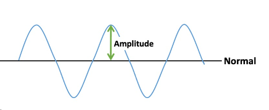 for example temperature or radio.
With a microphone it uses airpressure, the week signals can be amplified.
for example temperature or radio.
With a microphone it uses airpressure, the week signals can be amplified.
- Digital high / low, On or of like a switch.
Communication from the sensor to the microcontrollers
1wire, famous for their temperature sensor
I2C (digital protocol) (in arduino it’s called two wire interface) 7-bit address and most of them are fixed.
SPI. changes bits between main - secondary (MISO-MOSI) everything will talk at the same time. use Chip Select to chose with peripheral you want to talk to. SD cards use this protocol it’s fast.
Serial also revert to as UART Rx and Tx with a baudrate
GPIO Low 0 to 1/3 VCC. High 2/3 VCC to VCC more efficient to have a pull-up instead of a pulldown resistor
PWM Can be used as input’s to
digital read - digital values
analog rad - analog values
Units: SI System
- seconds s
- meter m
- kilogram kg
- ampere A
- kelvin K
- mole mol
- candela cd
Everything else is derived volt = watt / ampere watt = joule / second joule = newton * meter newton = kg * meter / second / second
Buttons and switches Watch out for “debouching” use a short time delay to prevent the debouching for reading a button Hall-effect sensors magnets you can use for measuring the magnetic field invert it to change the direction. If you rotate the sensor without a magnet near, there is a tiny change that’s earths magnetic field. Use the magnet to know if something is close by for example.
- you can give the magnetic field a strength and a direction to measure more that close or far.
- SCL clocking, SDA data, use pull up resistors 1k or 5k to pull the pin to high.
- I2C library is called Wire.begin
- these I2C devices protocols can be complicated
- potentiometer changeable resistance to set the voltage
Step response
- You step response for interface sensor on the outside of your object, you don’t have to see it, it can be wood or a book.
- Qtouch for measuring capacitance you can use it to track position
- You can you is to measure pressure
- Pick the time and measure the voltage or turn it around it can be in 10 microseconds
Temperature sensor
- warm-up and cools down the part you touch
- MTC for lower temp, RTC for higher temp
- bridge to measure a small changes in temperature
Light sensor
- phototransistor
- synchronic detection, measure the light by including a LED. Turn the LED on and of. Measure the difference when the LED is on and of instead of measuring surrounding light directly to smooth out your data from errors.
- Use light wavelength to detect color
Doppler Radar
- sends a signal back and looks for a change in frequency, they don’t need optical sight, it measures motion but not distance
Distance sensor
- optical, to measure distance for example in mm, measure in picoseconds using a light pulse and measures the return of the light at picoseconds to measre the distance.
- Sonar, LIDAR
GPS
- cheap modules for this, you need to see the sky for it to work.
movement
- tracing orientation sensor BNO085, 9 sensors it gives you the absolute orientation and how you are moving through space
- acceleration acts like gravity so you can measure it going up and down
Sound
- microphone measuring audio so you can sense a sound, amplify it store it analyze it I2S standard libraries for microphones
- to measure vibrations you can use a piëzo disk
- to measure force load cell to measure weight
- Capacitive force sensors
Angle
- encoder to measure a rotary angle or a rotary capacitor
Pressure
- measure altitude with air pressure
- measure your pols
- measure air pollution
- measure gasses
Imaging
- Sense is the XIAO EPS32 with camera with this camera you can read images and use the information for certain goals.
Group assignment
steps for working with a sensor
- check the schematic of the the sensor, connect it to your microcontroller
- check the data protocol
- find an library with an example
- understand the example and change the pin- outs, change the example if necessary
- wire up the sensor
- If it’s uploaded correctly try to read it’s value’s
joe, Leo and edwin documented the group work on their personal pages, here you can find the code we used to program the sensors.
- We will start with the DHT11 temperature / humidity sensor
- After this we will work with a 503 linear hall effect sensor
- Edwin tried some stuff using an RGB LED as a light sensor
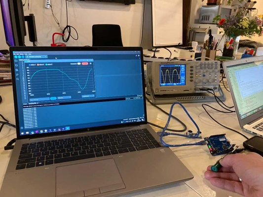
temperature / humidity sensor We are using the following pins from the arduino uno for this sensor:
- Signal - 7
- VCC - 6
- GND - 5
Important things I learned during the process:
- In the code we set pin number 5 to 0, so LOW, to make it a ground. To do this we have to tell arduino it’s an output.
- When deciding if a pin is an input or output, think from the microcontroller so the source starts there. So VCC and gnd are both outputs but the VCC is set to HIGH
- The signal is an input pin
- You store data from the sensor inside a long with is a series of characters in this case numbers.
- In the serial begin make sue you work with the right baudrate, same for the serial monitor. In this case Serial.begin(9600); this depends on the micro processor
- We had some trouble with the sample code from the library we found not fully functioning, I learned their are multiple ways of solving this stuff but I think for a started it’s good to try multiple sample code and library’s and check if it’s supported for the micro controller and sensor before settling on one.
 Picture form Leo
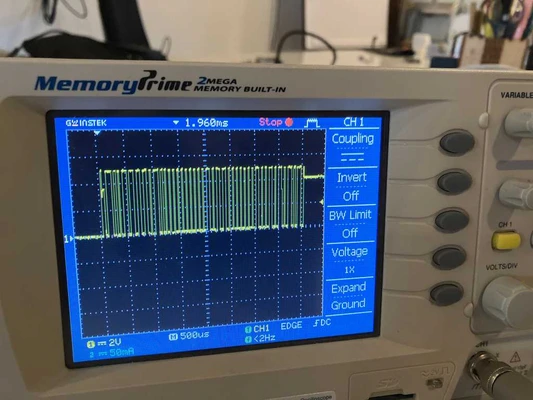
503 linear hall effect sensor
I missed out most of this second part of the group assignment discussing my midterm review with Michelle and seeking for som advice from Erwin but I had a look when the sensor was working and the oscilloscope what hooked up. You can see the wavelengths respond on the distance of the magnet to the sensor!
 picture from Leo
Individual assignment Step Response
For the individual assignment I’m going to try out step response. I already tried some things with conductive ink, coper fabric and velostat to create a touch sensor for the input pillow for my final project but after the presentation of Neil on step response I’m thinking this can be really nice because it can be an invisible sensor as soft as fabric so i’m going to give it a go.
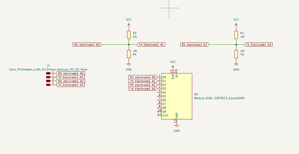
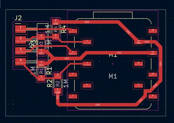
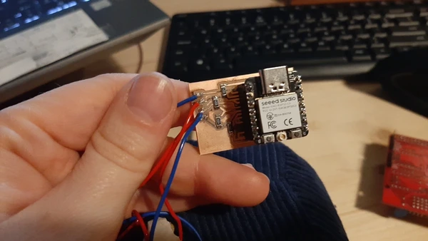
I used adrian’s stepresponse example of the FabXiao board. And I made a new design in KiCAD going for two big surfaces and two capacitive sensor with 1M Ohm resistors readings on this first try creating an actual pillow. And for this I used the Xiao ESP32-C3 micro controller which I also want to use for my final project.
Making the PCB
- Had some issues with exporting drill files and run out of time, so I made it without
- first try PCB had to tiny pads to solder the thread for the step response plates -> redesigned it using different footprint
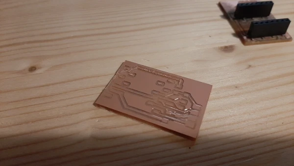
- second try PCb was not level enough so on the left upper side the copper is trill in it’s trace so it etched. The other corner had a lot of burrs so definitely a leveling problem
- In Fablab Arnhem I used the Lunyee for the first time so I flattened the base drawing a rectangle in Coreldraw and using mods. I used a piece of leftover POM and it milled nicely
- First try on this machine but third try of this PCB design I milling the traces and they look perfect! I also worked with a probe to set the Z origin using universal Gcode sender.
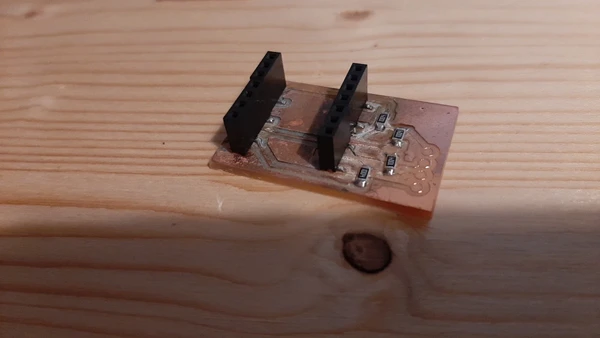
- Soldered everything with lots of flux because you can nicely tin the pads before adding extra tin to fasten the component
- tried to run the code from Adrians sample only changed the pin outs
- Receiving meaningless measurement that don’t respond. I killed the mapping code line //result1 = map(result1, 5000, 55000, 0, 1024); // Map the values for sensor 1 still have the same issue**
- using the multimeter to check my circuit, figuring out my pinouts are all connected the problem was the electro wire connected to the two coper plates (in my case coper fabric) were touching the coper and are making an unwanted bridge, so I fixed it i thought and measure again. I keep having weird connections I now look closer and realize I didn’t clean my PCB properly after milling and after using the flux and this black smudge that is between the traces is making these unwanted connections! What in the world…. I receive a tip to put the PCB in the ultrasonic cleaned with isopropanol alcohol (without the micro controller) and it cleaned it properly. I will not forget this :D It now finally works!
 Coding:
//tx_rx03  Robert Hart Mar 2019.
//https://roberthart56.github.io/SCFAB/SC_lab/Sensors/tx_rx_sensors/index.html

//Modified by Adrián Torres Omaña
//Fab Academy 2023 - Fab Lab León
//Step Response TX, RX
//Fab-Xiao

//  Program to use transmit-receive across space between two conductors.
//  One conductor attached to digital pin, another to analog pin.
//
//  This program has a function "tx_rx() which returns the value in a long integer.
//
//  Optionally, two resistors (1 MOhm or greater) can be placed between 5V and GND, with
//  the signal connected between them so that the steady-state voltage is 2.5 Volts.
//
//  Signal varies with electric field coupling between conductors, and can
//  be used to measure many things related to position, overlap, and intervening material
//  between the two conductors.
//


long result;   //variable for the result of the tx_rx measurement.
int analog_pin = A0; //  GPIO 27 of the XIA0 RP2040 or ESP32-C3 pin A1
int tx_pin = D1;  //     GPIO 28 of the XIAO RP2040 or ESP32-C3 pin D2
void setup() {
pinMode(tx_pin,OUTPUT);      //Pin 2 provides the voltage step
Serial.begin(115200);
}


long tx_rx(){         //Function to execute rx_tx algorithm and return a value
                      //that depends on coupling of two electrodes.
                      //Value returned is a long integer.
  int read_high;
  int read_low;
  int diff;
  long int sum;
  int N_samples = 100;    //Number of samples to take.  Larger number slows it down, but reduces scatter.

  sum = 0;

  for (int i = 0; i < N_samples; i++){
   digitalWrite(tx_pin,HIGH);              //Step the voltage high on conductor 1.
   read_high = analogRead(analog_pin);        //Measure response of conductor 2.
   delayMicroseconds(100);            //Delay to reach steady state.
   digitalWrite(tx_pin,LOW);               //Step the voltage to zero on conductor 1.
   read_low = analogRead(analog_pin);         //Measure response of conductor 2.
   diff = read_high - read_low;       //desired answer is the difference between high and low.
 sum += diff;                       //Sums up N_samples of these measurements.
 }
  return sum;
}                         //End of tx_rx function.


void loop() {

result = tx_rx();
//result = map(result, 1000, 50000, 0, 1024);  //I recommend mapping the values of the two copper plates, it will depend on their size
Serial.println(result);
delay(100);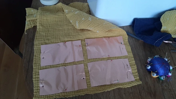
}- I upload the code again and I can now actually read the differences when touching the object I made a sandwich of cotton fabric, coper fabric plate 1, foam, coper fabric plate 2, and cotton fabric on top. when I touch the fabric I see big changes in the sensor data. I try to read the highest and lowest reading and use the map function to map the data.
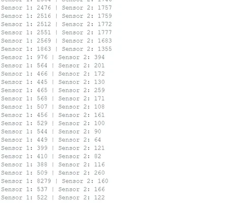
- I asked chat GPT to help me generate the second sensor reading using the following prompt:
this code is for a capacitive touch (step responds) sensor on the XIAO ESP32C3 I want to make two capacitive sensors can you help me rewrite the code? I want to use pin A2 and D3 for the second capacitive touch I used the sample code of Adrian as the input for chatGPT.
//tx_rx03  Robert Hart Mar 2019.
//https://roberthart56.github.io/SCFAB/SC_lab/Sensors/tx_rx_sensors/index.html

//Modified by Adrián Torres Omaña
//Fab Academy 2023 - Fab Lab León
//Step Response TX, RX
//Fab-Xiao
// Modified by ChATGPT and Vera Schepers to make a double reading

//  Program to use transmit-receive across space between two conductors.
//  One conductor attached to digital pin, another to analog pin.
//
//  This program has a function "tx_rx() which returns the value in a long integer.
//
//  Optionally, two resistors (1 MOhm or greater) can be placed between 5V and GND, with
//  the signal connected between them so that the steady-state voltage is 2.5 Volts.
//
//  Signal varies with electric field coupling between conductors, and can
//  be used to measure many things related to position, overlap, and intervening material
//  between the two conductors.
//

long result1;   //variable for the result of the tx_rx measurement for sensor 1
long result2;   //variable for the result of the tx_rx measurement for sensor 2
int analog_pin1 = A0; //  GPIO 27 of the XIAO RP2040 or ESP32-C3 pin A0 for sensor 1
int analog_pin2 = A2; //  GPIO 27 of the XIAO RP2040 or ESP32-C3 pin A2 for sensor 2
int tx_pin1 = D1;  //     GPIO 28 of the XIAO RP2040 or ESP32-C3 pin D1 for sensor 1
int tx_pin2 = D3;  //     GPIO 28 of the XIAO RP2040 or ESP32-C3 pin D3 for sensor 2

void setup() {
  pinMode(tx_pin1, OUTPUT);      // Pin D1 provides the voltage step for sensor 1
  pinMode(tx_pin2, OUTPUT);      // Pin D3 provides the voltage step for sensor 2
  Serial.begin(115200);
}

long tx_rx(int tx_pin, int analog_pin) {
  int read_high;
  int read_low;
  int diff;
  long int sum;
  int N_samples = 100;    // Number of samples to take. Larger number slows it down, but reduces scatter.

  sum = 0;

  for (int i = 0; i < N_samples; i++) {
    digitalWrite(tx_pin, HIGH);         // Step the voltage high on one conductor
    read_high = analogRead(analog_pin); // Measure response of the other conductor
    delayMicroseconds(100);             // Delay to reach steady state
    digitalWrite(tx_pin, LOW);          // Step the voltage to zero
    read_low = analogRead(analog_pin);  // Measure response again
    diff = read_high - read_low;        // Desired answer is the difference between high and low
    sum += diff;                        // Sum up N_samples of these measurements
  }
  return sum;
}

void loop() {
  result1 = tx_rx(tx_pin1, analog_pin1); // Measure response for sensor 1
  result2 = tx_rx(tx_pin2, analog_pin2); // Measure response for sensor 2
  //result1 = map(result1, 5000, 55000, 0, 1024); // Map the values for sensor 1
  //result2 = map(result2, 5000, 50000, 0, 1024); // Map the values for sensor 2
  Serial.print("Sensor 1: ");
  Serial.print(result1);
  Serial.print(" | Sensor 2: ");
  Serial.println(result2);
  delay(100);
}
sewing
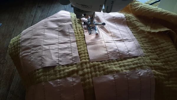
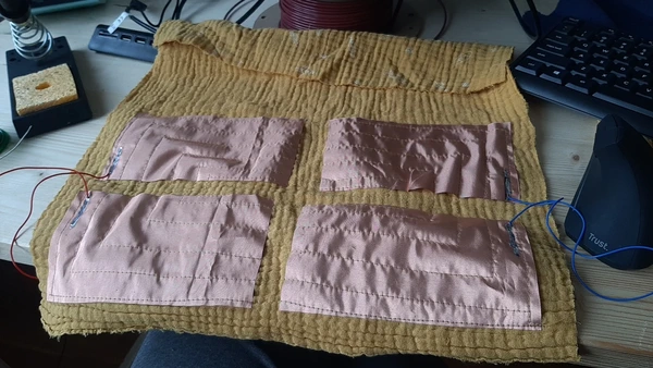
I start working on the final project pillow now and sew the design I made in week 2 using clo3D.
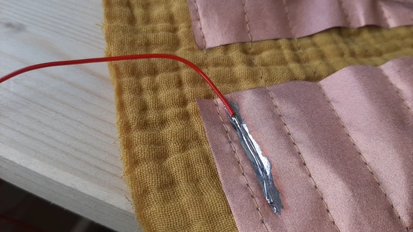
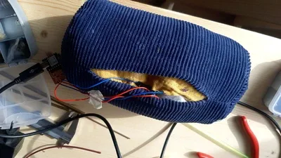
I use my sewing machine and start with pinning down the conductive fabric, solder the threads to the pads later and sew everything the wrong way around. I then flip the design trough the hole where I will later put the zipper.
Embroidery test
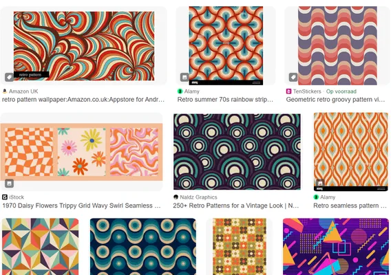
To make the pillow even more tactile I want to experiment using the Brother VR embroidery machine for making the capacitive touch pads. So It will be more centered and smaller more button like. I got my inspiration from these patterns form the 70ties and quickly designed a shape with copper fabric on the back that functions both as a fleece linen and to make the a tight connection to fasted the copper fabric.
I used the offset tool and the circle tool to create this design in Corel Draw exported it as an EMF file and open this file with the software PE design to generate the stitches.
- File
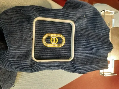
 The second design I made the embroidery frame came loose and I broke the needle.. so I have to do it again. But I can still use it for a little test and I’m curious with mapping data I will receive on the serial monitor.
Reflection
Things I have to figure out:
- readings seem to be changing a bit when the micro controller is plugged out and later plugged in again so it’s not as constant as I would like it to be.
- mapping can get spikes that go above the max and min number it should map
- the side you touch the pillow makes a huge difference in the values to get so one side gives values of about 20 and the other side of 1200 for example and without touching it it was around 5000. I assumed that the side you touch wouldn’t matter.
- try out step response with the embroidered pads
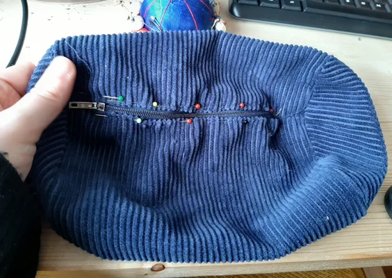
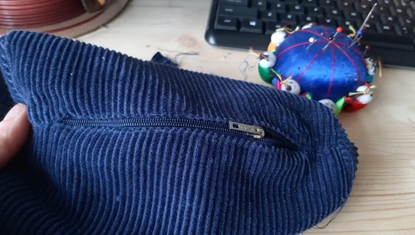
- sew the zipper in the pillow
I jumped in to the world of sensors and input devices learned a lot from the lectures that I didn’t know. Have learned a lot about the Lunyee milling machine this week. I also learned about step response and got hands on making the pillow with was fun. this week was also a lot of trouble shooting.
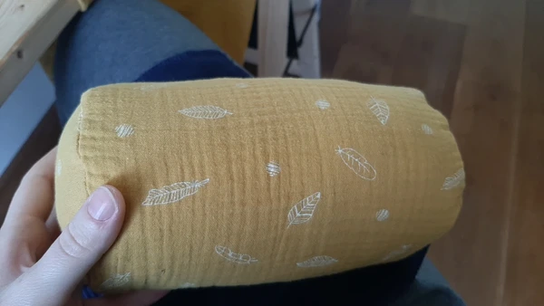
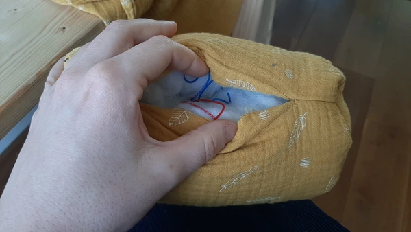
During the global review I showed the pillow to Neil to help me understand what’s going on with these odd data readings. He helped me understand I need to put one fabric plate in the middle of the pillow and wrap the other one around it like a cannoli so the sensor data will be more consistent. Because I made a pillow inside a pillow case I can reuse the pillowcase, but I will have to make a new inside pillow following the principal.