Process
During the first week, I started brainstorming about my final project. Since that I mapped my making process on this page. If you want to read about the idea, the inspiration, time management, the BOM(bill of materials), the reflection and so on. You can have a look at the Final Project page. This process page is dedicated to the making process. Including tests of things I did and did not use for making the final project. At the bottom of the page you can download all the files to make this project yourself. Below you can quickly navigate to a certain topic.
Summary

Making thoughts
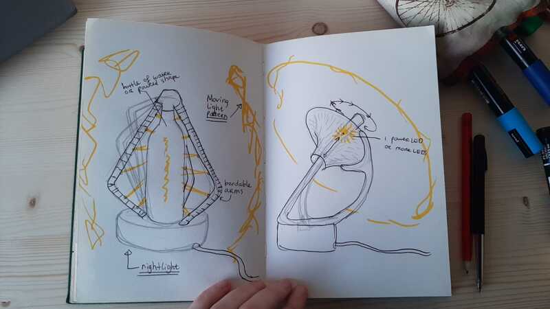
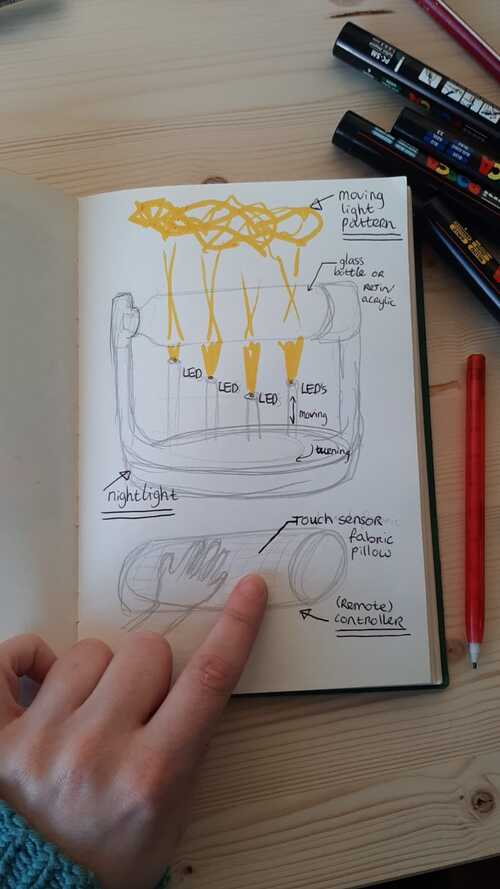
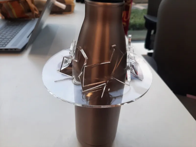
Below you can find the sketches of different ways of making the dream light. I quickly take you through the process of deciding the direction I went for. At first I wanted upcycle a simple glass object like a glass bottle from sirup or oil, to make the nightlight. I tried some stuff to see how it reflects the light and made some sketches but I quickly changed my mind because:
- The goal is to create as much as possible yourself
- The way the light reflects depends on the shape of the bottle and I want it to be something more universal. Now I would have to build around one specific object as in my previously made artwork and sketches below, it will be a one of a kind kind of thing. Unless you happen to have the exact same shape.
So with the open source spirit in my mind I decide I don’t want to be stuck to the bottle idea.
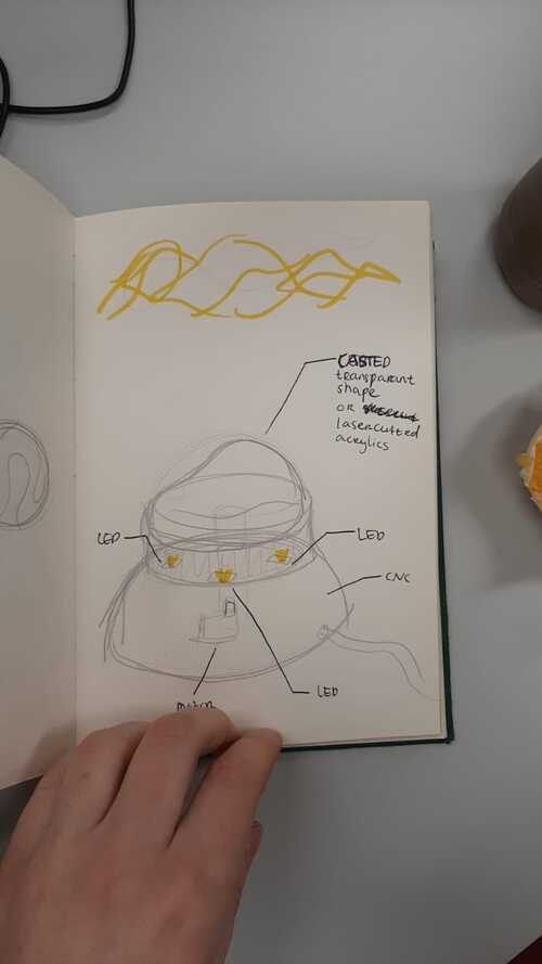
I’m thinking about making a base, maybe from CNC milled wood, with LEDs in the base. That gives me a lot of space to experiment with the light bending object on top. Like pouring it in resin, vacuum forming the shape or making it with the laser cutter from acrylics. I sketched this idea:
I made a render of this idea in week 2.

Since then I have new ideas about how to make the light patterns.
One idea is making an kinetic moving construction so the light will bend in all kind of directions
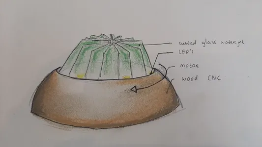
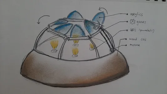 The other one is making a glass top with water jet cutting glass and make a striped pattern that can rotate. I did end up making this glass object idea during Wildcard week but I did not use it for the final project.
The making of
Input sensor for the pillow
At Waag there are students that follow the fabricademy course and I think I can get more inspiration for the pillow looking in to their research. I would like to experiment with different techniques and let the experiment direct the shape of the pillow.
I made a render of a possible pillow made my screen printing a conductive design during Computer-aided design:

After a bit my idea changed from screen printing a conductive ink towards vinyl plotting touch sensors:
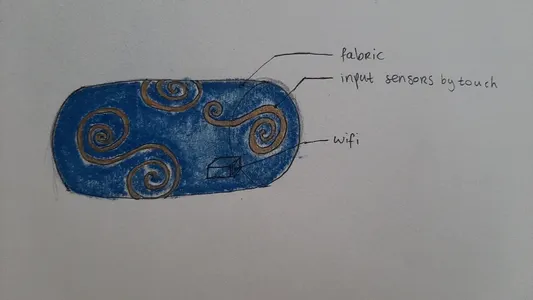
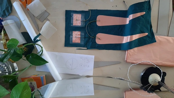
For the input pillow I wan’t to try different ways of making the input sensor on / in the pillow. I start by trying to screen print a design with conductive paint I made myself, major fail there so I continue with conductive paint I boughed. This was better but not the look I wanted. I continued experimenting with vinyl cutting coper fabric and sewing velostat for making pressure sensors. You can read about it below. At the and I decides to work with step response sensors using coper fabric and hiding them inside the pillow. Making It invisible for the eye.
Conductive ink - capacity sensor
I want to try to make a screen print with conductive paint on fabric for the input pillow to make a capacity sensor.
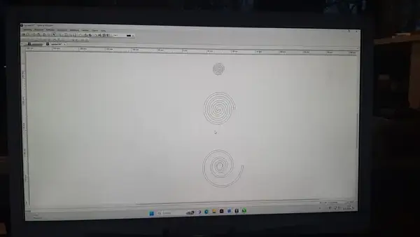
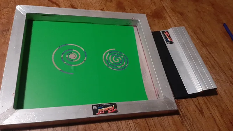
I start with playing with the spiral tool in Corel Draw to make a shape. I try the different functions that the tool offers like the amount of turns and the distance between the lines. It can be evenly distributed or centering at the circle. I thing I will try them both. And I export the drawings as .EPS files.
 With the Summa vinyl cutter an the Fablab Arnhem I cut out a peace of leftover foil with the pressure set to 60 grams, weed the actual sticker itself so I’m left with the outer shape and use transfer foil to put it on the screen.
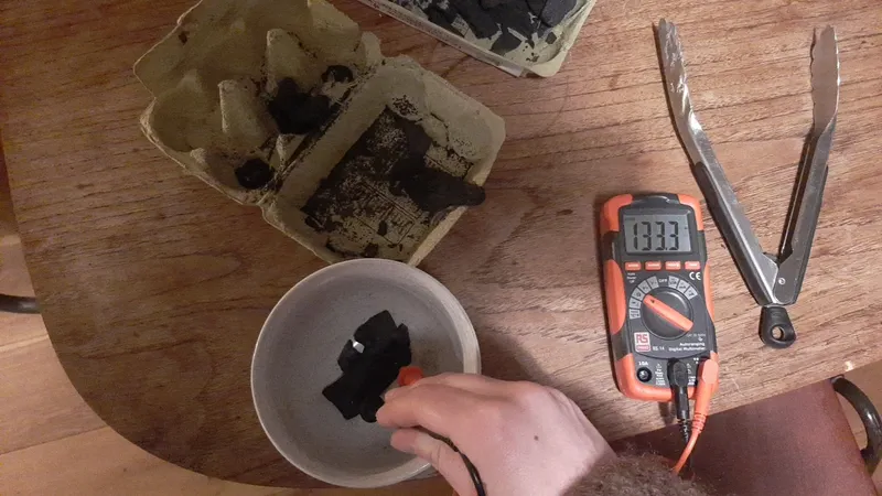
 I follow this tutorial showing how to make conductive paint from charcoal. I have a bag of charcoal for barbecuing and start with using the multimeter in the Ohm function and I try find the peaces with low resistance, I found some peaces of <80 ohm but it’s kinda hard. A lot of the peaces have a very high or unmeasurable resistance.
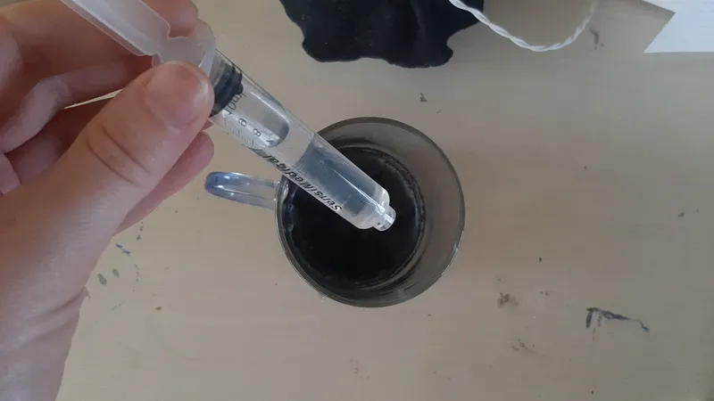
 And put them in the blender. I take away the clean water on top after letting it rest and put a little bit of textile binder instead of glue (what they use in the tutorial).
 I try to screenprint with it but the emulsion does not pass through the sieve. I strain the ink and try again, still no success.
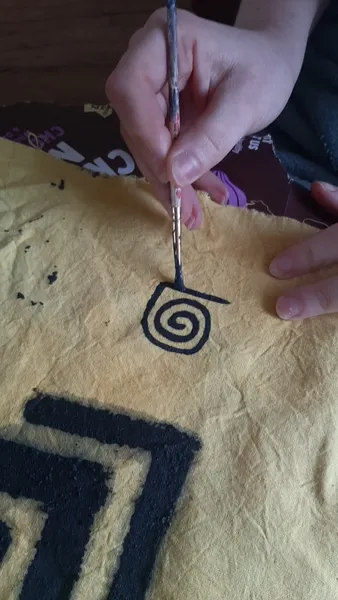
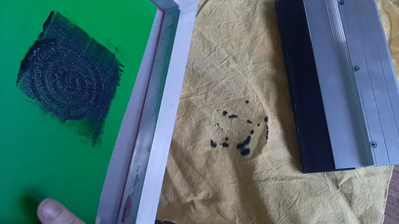 I end up painting a shape and after I let it dry I test it but the resistance is very high I measure Mega ohms now, and on some parts I can’t even measure it because it’s to high. The paint is leaving black prints on your finger when you touch it so it’s not a success at all.
Follow up: I ordered this conductive paint for about 11 euro’s and mixed it with a bit of textile binder again to make sure it will attach to the fabric. I use a rate of 1:1 of the paint and binder and pain a shape on the fabric again. I use the same code described at the coper fabric capacity sensor below and was able to read numbers from the serial monitor.
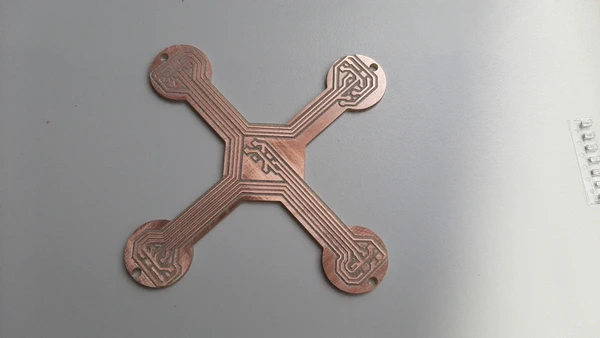
Coper fabric vinyl cutting - capacity sensor
I got a tip from Michelle looking in to coper fabric who worked with this during fabacamdemy originally inspired by this project kobakant tutorial to make the conductive pillow touch sensor. You can find instructions of working with the vinyl cutter machine on Week computer controlled cutting. And on Week electronics design I tried cutting a pcb with the same machine and material. I got the tip for using vliesofix to attach coper fabric to fabric from Michelle and I used the vinyl cutter instead of the lasercutter because I don’t know what type of material vliesofix is made from and if I can safely cut it with the lasercutter and I think it should be possible to cut it with the vinyl cutter as well.
I used the following materials:
- vliesofix I got it from a local store that I bought for 0,60 cents
- coper fabric I got it from amazon fot about 11 euros
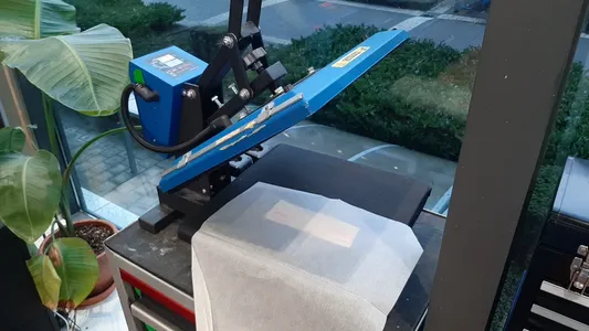
I start by using the heat press to attach one side of the double sides vliesofix to the coper fabric. I put the heat at 100 degrees, test the pressure by turning the big black screw on top and make sure I feel resistance from the press and pressed it for a sew seconds, that works nicely!
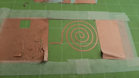
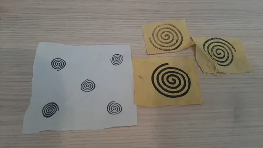
I put the peace of coper fabric with the vliesofix material attached to the backside on the cricut sticky mat, and I use some extra tape to make sure the material stays in place. I do some test runs using the test function of the machine and the pressure of 20 grams works best for cutting through the coper. I export my design as an EPS file and send it to the plotter. Weeding the material is easy I do have to watch out that the spiral does’t get loose from the sticky mat. I it looks very good and i’m happy so far!
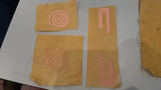
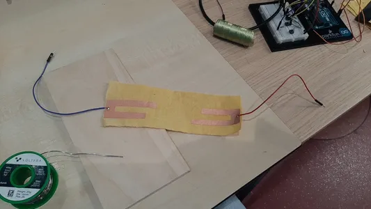
I cut peaces of yellow cotton fabric and use a transfer sticker to transfer the spiral to the fabric without deforming it. I use the heat press again same temperature /pressure and length as step 1. I will now attach the the coper fabric to the yellow fabric by heating the vliesofix again. I press it leaving the transfer sticker on. Because I don’t want to deform the spiral. The vliesofix material only becomes sticky when you heat it so it wont attach to the fabric before. The transfer foil comes of easily and there is no glue or anything left and the coper fabric is nicely attached to the yellow fabric! It looks really good no loose edges.
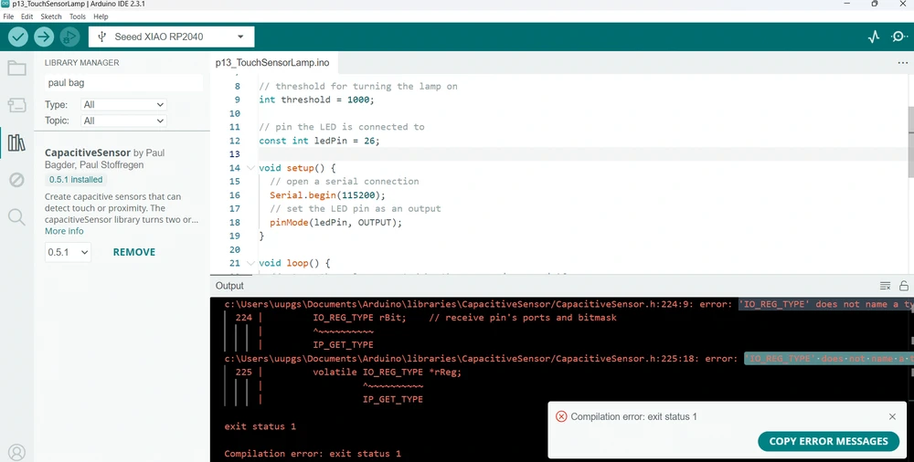
I open Arduino IDE 2.3.1. and use the code from the arduino starter kit that uses an capacity sensor library by Paul Badgers and try to get it to work using the micro controller I made during the electronics design week. I get an error and remember that chips have become faster to I check the baud rate of the XIAO RP2040 and change the code to 115200 instead of 9600. Thinking it will work now! nope.. I googled the error and after some rome research I can make the conclusion that the library that i’m using is not supported by the XIAO RP2040, so I need to change library or micro controller. For now I will change the controller because I can do this quickly, find an arduino uno laying around in the lab and use this to test if i can read values.
I start from this example code:
Example code capacity sensor Arduino
/*
  Arduino Starter Kit example
  Project 13 - Touch Sensor Lamp

  This sketch is written to accompany Project 13 in the Arduino Starter Kit

  Parts required:
  - 1 megohm resistor
  - metal foil or copper mesh
  - 220 ohm resistor
  - LED

  Software required :
  - CapacitiveSensor library by Paul Badger
    https://www.arduino.cc/reference/en/libraries/capacitivesensor/

  created 18 Sep 2012
  by Scott Fitzgerald

  https://store.arduino.cc/genuino-starter-kit

  This example code is part of the public domain.
*/

// import the library (must be located in the Arduino/libraries directory)
#include <CapacitiveSensor.h>

// create an instance of the library
// pin 4 sends electrical energy
// pin 2 senses senses a change
CapacitiveSensor capSensor = CapacitiveSensor(4, 2);

// threshold for turning the lamp on
int threshold = 1000;

// pin the LED is connected to
const int ledPin = 12;


void setup() {
  // open a serial connection
  Serial.begin(9600);
  // set the LED pin as an output
  pinMode(ledPin, OUTPUT);
}

void loop() {
  // store the value reported by the sensor in a variable
  long sensorValue = capSensor.capacitiveSensor(30);

  // print out the sensor value
  Serial.println(sensorValue);

  // if the value is greater than the threshold
  if (sensorValue > threshold) {
    // turn the LED on
    digitalWrite(ledPin, HIGH);
  }
  // if it's lower than the threshold
  else {
    // turn the LED off
    digitalWrite(ledPin, LOW);
  }

  delay(10);
}- I delete everything that has something to do with the LED because I just wan’t to read the sensor value for now in the Serial Monitor. And add the map function. This will recalculate the output values between the number you type there so for example: Instead of mapping a value number between 0 ans 2000 you can scale this bac to between 0 and 10. So an original value of 1000 will be 5 now on a scale from 0 to 10. This is the actual code I used to make the video below:
Altered code capacity sensor Arduino
// create an instance of the library
// pin 4 sends electrical energy
// pin 2 senses senses a change
CapacitiveSensor capSensor = CapacitiveSensor(4, 2);
void setup() {
// open a serial connection
Serial.begin(9600);
}
void loop() {
// store the value reported by the sensor in a variable
long sensorValue = capSensor.capacitiveSensor(30);
// scale the numbers back for you to make it more readable.
map (sensorValue, 0, 1023, 0, 100)
// print out the sensor value
Serial.println(sensorValue);
}
delay(10);
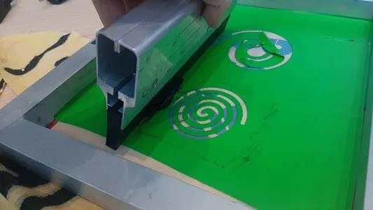
}With the new paint I was able to test screenprinting the designs. With the multimeter I measured the Ohm resistance of the material. With the smaller lines it’s to high but the bigger lines look fine!
It took me a few tried to get the pressure right and and up with a nice screenprinted spiral.
Velostat and coper fabric - Pressure sensor
In the local meeting I got the change to share my final project and got the tip from Adrian to look at the material velostat, so I ordered this to. It’s a pressure sensitive conductive sheet if you put pressure on it the resistance becomes less. Ardian shows the E-monsters project made with velostat, the led changes color when the fabric is pressed. Velostat is a Carbon impregnated black polyethylene film material with a volume resistivity is <500 Ohms/cm I read in his documentation you can find here flex sensor this also uses the Ardianino board I made so it’s very helpful. I’m going to try to make two different versions of this pressure sensor. One laminated in plastic that could go inside of the pillow and another one with fabric that could be sewed on top of the fabric.
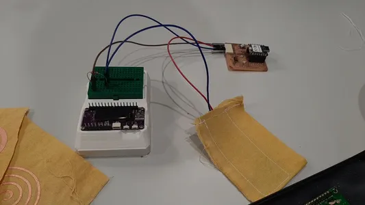
In have the wires of the VCC and ground soldered to the coper fabric. I will add an 10k pull-down resistor at the sensor signal output. And an other wire for communicating the signal to arduino pin 0I use the microcontroller XIAO Rp2040 and use the following code from Adrian’s page about the Textile Flexure sensor.
Textile Flexure Sensor code
//Fab Academy 2021 - Fab Lab León
//Textile Flexure Sensor
//Adrianino
//ATtiny1614
int sensorPin = 0; // analog input pin to hook the sensor to
int sensorValue = 0; // variable to store the value coming from the sensor
void setup() {
Serial.begin(115200); // initialize serial communications
}
void loop() {
sensorValue = analogRead(sensorPin); // read the value from the sensor
sensorValue = map(sensorValue, 0, 1024, 0, 1024);
Serial.println(sensorValue); // print value to Serial Monitor
//mySerial.println("x"); // print value "x" to Serial Monitor
delay(500); // short delay so we can actually see the numbers
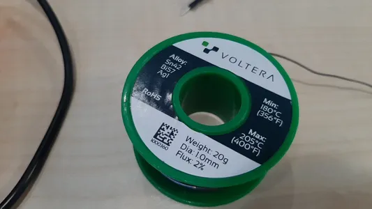
}I start with cutting the coper fabric in two peaces and use the heat press to fix the vliesofix to the yellow fabric the same way I made the capacitive sensor. Soldering on the coper fabric is difficult because you will burn holes in it with normal tin. I found this low temperature solder tin from Voltera. It’s expensive but works super nice. I soldered the wires at a temperature of 200 degrees and now have my base.
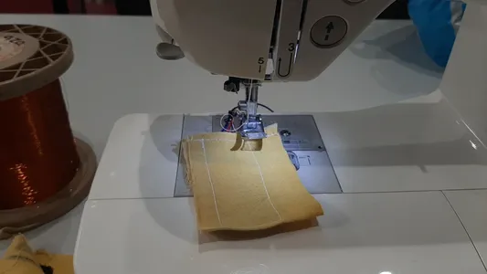
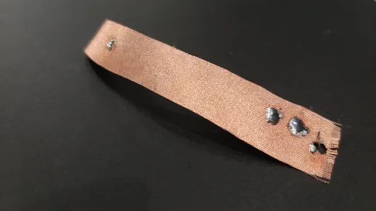 I fold the fabric in half, put a peace of velostat between it an sew it together using the sewing machine. Watch out for you needle on the parts that have tin.
During week 6 embedded programming I tested and programmed the velostat pressure sensor by changing the color of the Neopixel depending on the pressure and a second version making the neopixel dim.
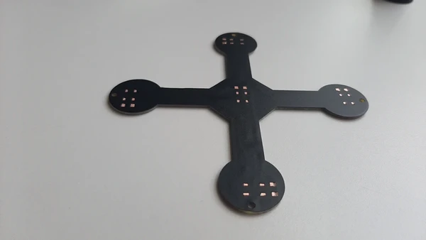
Step response
During week 11 input devices I learned about step response. I made the first actual pillow using this technique because I like the fact that it needs no library or capacitive pins. I’ve been working on a reliable sensor since. You can read all about the process during system integration week.
Mechanical movement - Kinetic art
For the mechanics of my project I start working on a system based on beveled gears but I switch the gears for universal couplers during the process.
Beveled gear
During 3D printing and scanning week 5 I made a design for the beveled gears to create this rotating movement inspired by this video from Geo3Dprint I found creating an Antony howe inspired sculpture.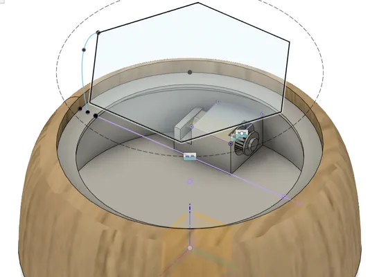 It will be placed on top of a base which will include the motor to drive the mechanism and the PCB with the neopixels.
After printing it, you can find the result here
It will be placed on top of a base which will include the motor to drive the mechanism and the PCB with the neopixels.
After printing it, you can find the result here
I redesigned the beveled gears to get more grip
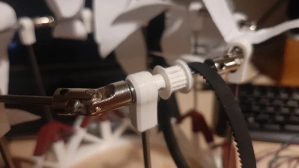
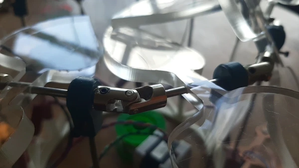
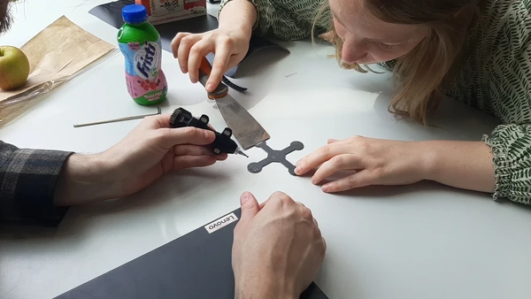
But during output devices I decided to go another rout and made a prototype using universal couplers so I could add a stepper motor before the end of the week to test it.
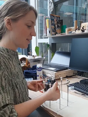
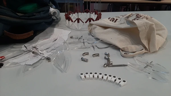
Universal couplers and bearings mechanism
I continued building on the prototype and design holders for the bearings. The bearings make the mechanism move smoothly. The holders I designed are to connect the 3 mm shafts to the base.
I build the mechanism with 3 mm shaft material. And here you can see the result.
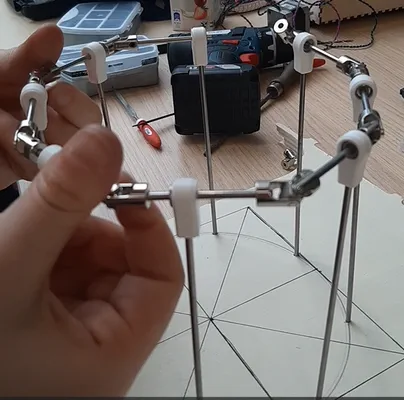
I draw the design on a wooden base and drill holes for the shafts. But the mechanism has to many degrees of freedom and it not turing properly.
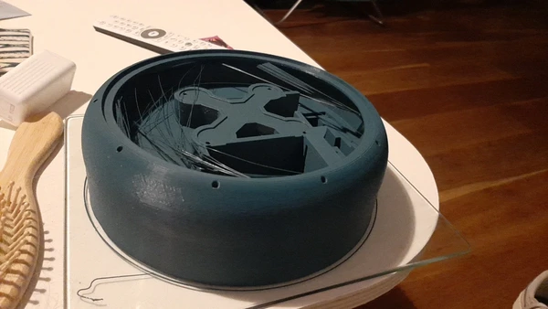
Base Design
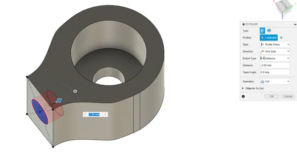
I start designing a base in Fusion360 to 3D print to give the shafts more support, because the wooden plate with drilled holes was not exact enough and not thick enough.
I start with creating the base with the holes. I used 0.1 mm offset for a perfect fit (on the bambulab).
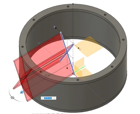
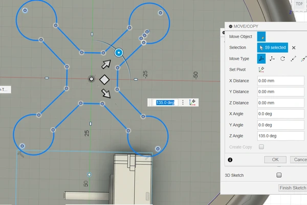
I decide to save material for 3D printing and build a triangle shaped structure instead of a solid. I start with drawing an X in the middle let it overlap and use the intersect tool to keep this part.
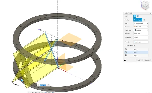 I use the circular pattern function to make it all the way around.
 After some fillets I print the first version on the Bambu labs using Bambu slicer.
The result it much better but the universal couplers still interlock, the have a small angle where they can turn and i’m pushing the limits a bit with this angle.
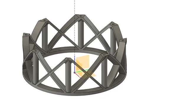
I decide to change my design from 8 couplers to 10, to make a wider angle and print it again.
I also designed new bearing holders and use inserts to prevent the holders to turn by clamping it using 2 mm bolts. This way I can fix the holder to the shaft in a specific angle and it can’t turn anymore. Limiting the degrees of freedom.
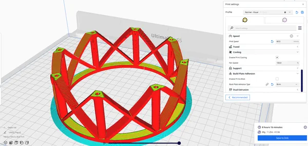
After some alterations this is the final design:
I printed 10 parts on the Ultimaker 2+ Extended using a layerheight of 0.2 mm and a wall / top bottom thickness of 1.2 mm. For all the 3D prints I use PLA filament from FromFutura.
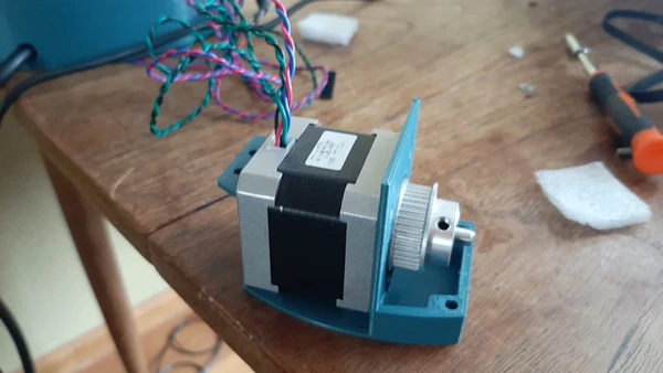
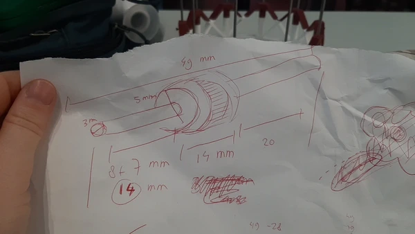
Driving the mechanism
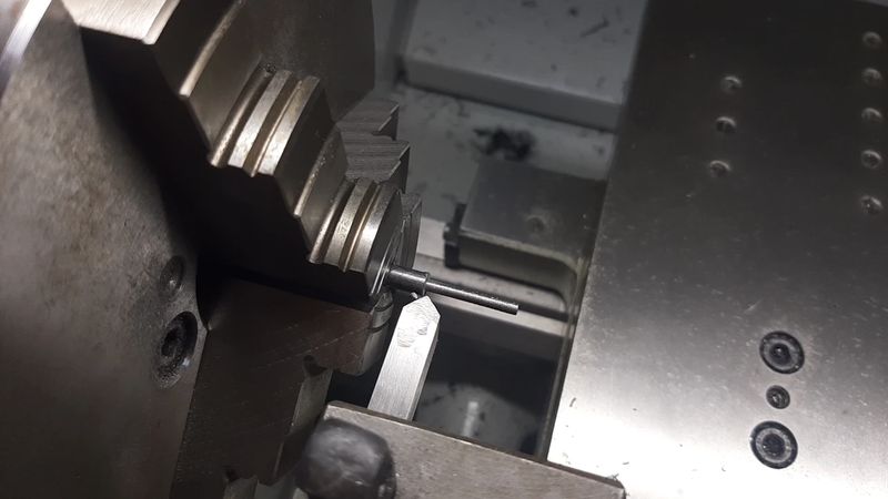
To drive the timing belt that will drive this mechanism I use a pulley I got from an old Ultimaker plus. It’s has a 5mm diameter hole. So I have to make a shaft with thickness 5mm in the middle and 3 on the edges. I make a drawing ot the part:
 And I use this lathe to make the part.
Turning the wheel the right way, hold it with two hands to prevent big mistakes
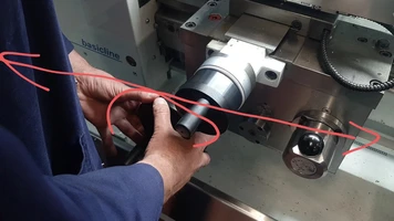
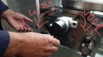
Setting X and Y coordinates for the measurements.
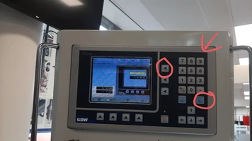
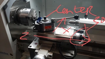
- Working on the part
System integration
During the last weeks of the Fabacademy I started designing the base of the nightlight and the casing of the pillow electronics. During week 17 system integration I start working and documenting on the electronics casing. You can head it here.
I kept working on this casing because I was not very happy with the first try.
I first include clicking fingers to open and close the casing. You can see them in this cut view.
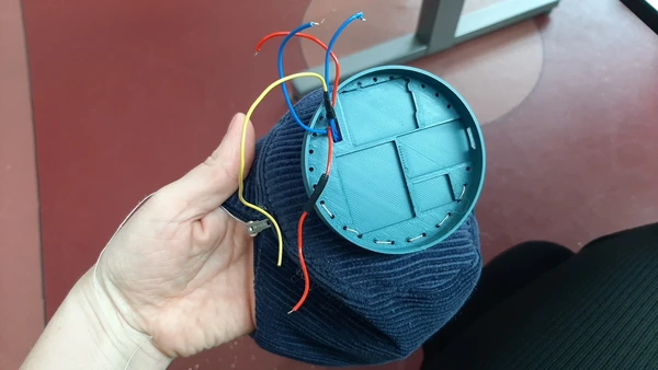
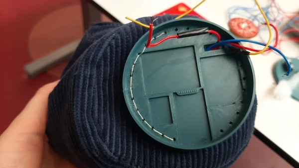
I want to change the position of the electronics to because it’s on the big side for the label idea I previously had. I played around with it and the new plan it to attach the casing on one side of the pillow. To do this i make holes in the back so I can (hand)sew it to the fabric.
Here you see the result.
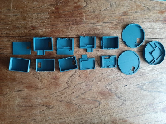
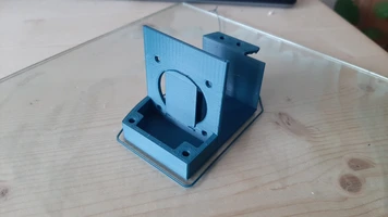
I made a second version that is more flat and has a round shape because I think it will fit the shape of the pillow better. So I start over and design it from scratch:
I print both the casing to see which one I like the best. Again on the Ultimaker 2+ Extended using 0.2 mm layerheight.
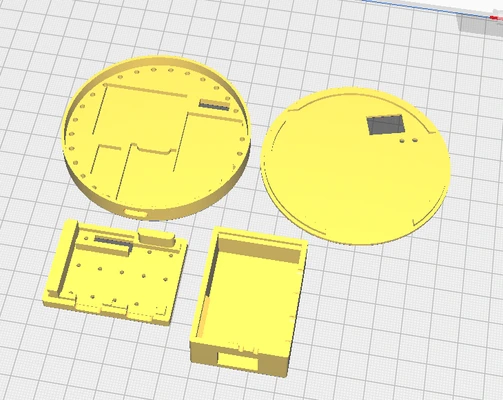
I decide to go for the round shape, It’s not having the clicking feature but it has a tight fit and I’m running out of time so I sew it together and put the electronics inside it.
Here you can see al my iterations during the process of designing this case:
nightlight system integration
Before I start I looked up 3D models I can use for my drawing.
- I got the design for the flat stepper motor here
- But I switched to a normal NEMA 17 stepper motor instead of the flat one after all.
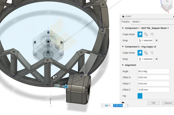
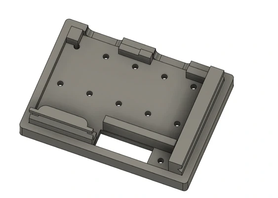
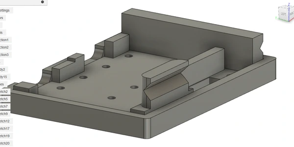
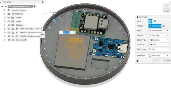
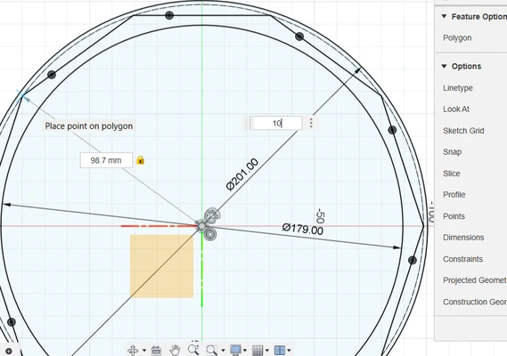
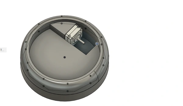
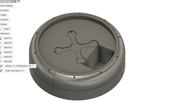
Here you can follow the design process in Fusion360. I start with drawing the base and using my calculations for positioning the holes.
I add the motor and make sure the axes of the motor it’s parallel to the shaft it will be driving by fixing it’s position with a joint.
I use the DXF outline drawing of the neopixels PCB I created and import this drawing within Fusion360.
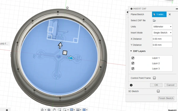 I position it and give it an offset and make a cut extrude.
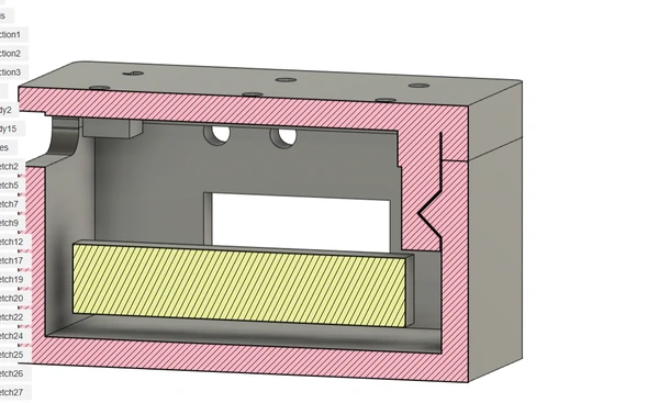
I add slides to mount the stepper motor and I add a big hole in the back for the power supply. I also add a little edge fot the lid to be positioned on top of.
I print the case using the Ultimaker 2+ Extended printing with a 0.25 mm layerheight and a cubic subdivision infill of 15 percent. Here you can see the support being printed were the power supply will be mounted.
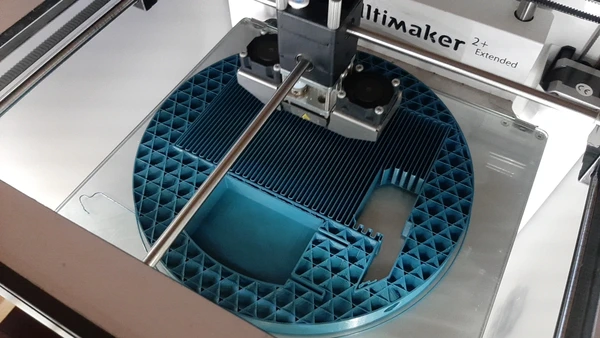
I have a big of stringing on top because of a chamfer not properly lining up giving it a tiny overhang. But It’s not an issue, I can cut the strings. The print took roughly one day.
Here you see it finished with the electronics and mechanical parts mounted.
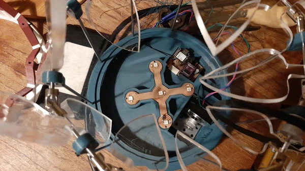
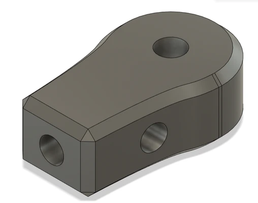
After this I continued working on a mount for the stepper motor.
This is the part I designed and it fits within the base of the nightlight. With bolts and inserts it’s mounted to the base.
 In the future I will make a stepper holder that can change the tension on the belt this way the length can be less precise.
Getting the right tension in the timing belt was a struggle. I measured the length for the right tension, cut the timing belt and I follow this tutorial video on how to connect the two ends. I did this three times before having the perfect belt.
I lasercutted the lid of the nightlight base. I first made a test fits with cardboard before
 I cut the final piece from PET-G.
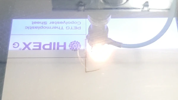 This closes the base with the electronics.
Light pattern reflective object
The mechanism I designed will have leaf like objects turning around to bend the light and create patterns on the ceiling. During molding and casting week I tried to pour the shape with a bio resin. You can read about it here, but this didn’t reflect the light as I hoped. So I decided to go for a lasercutted acrylic shape to bend the light.
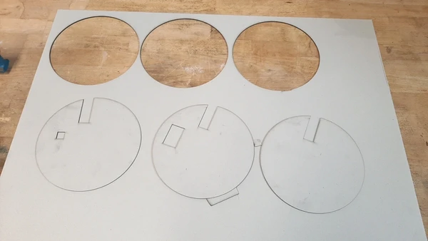
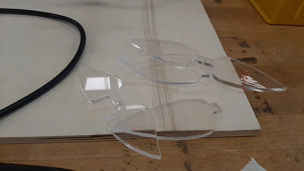
Acrylics light bending
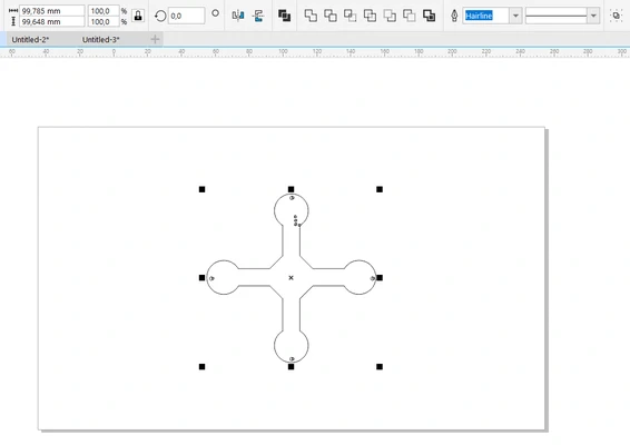
During one of the first weeks of Fabacademy I cut out a shape I designed in Coreldraw using the circular pattern function and the line tool. I cut 3 mm acrylic using the BRM machine I introduced in week 2.
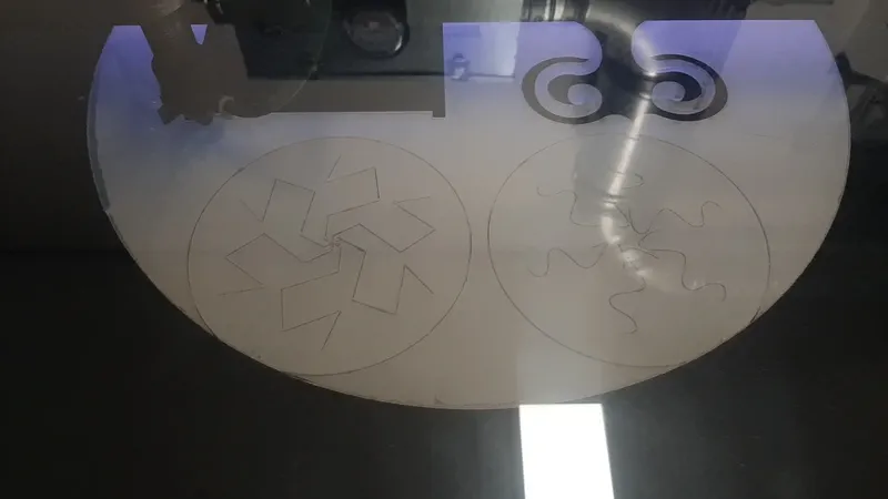 I heat the shape with a hot air gun afterwards and bend the shape so the light bends. Otherwise the light would just shine trough and you don’t see the light bending effects.
 Here you can see the light bending effect with the flashlight of my phone.

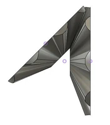
Weeks after I made this first test, I design the leaf shaped parts I use for the final project. since I now have a better idea of the size and amount of can be and used Fusion360 to draw the shapes.
I start with drawing the constraints so I know how big I can make the peases. After this I start working on the shape itself inspired by some google search pictures of leaves.

After drawing one leaf I copy and paste the shape and I design a range of leafs going from small to big.
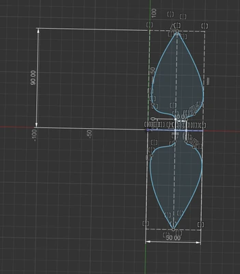
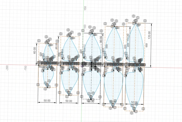
To export the drawing I give a thickness to the leafs and export them using the DXF lasercutter plugin.
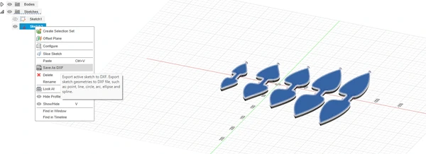
After exporting the shaped as a .DXF file I use deepnest to nest the parts efficiently.

I use 6 mm recycled acrylics to cut the parts.
After cutting them I use a 3 mm drill to drill holes in the middle of them. The shafts will go in the middle of the parts.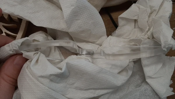
I use a heating wire to heat the horizontal middle of the leaf shapes and bend (twist) them with my hands afterwards.
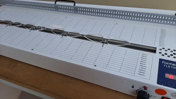
After drilling and bending all the shapes I make the chain by adding the universal couplers and the bearing holders.
 I use a tiny bit of superglue to glue the acrylics to the shafts. I eyeball the angle to make a full turn. I can easily change the angle later by unscrewing the universal coupler and turning the pease.
Here you can see the result!
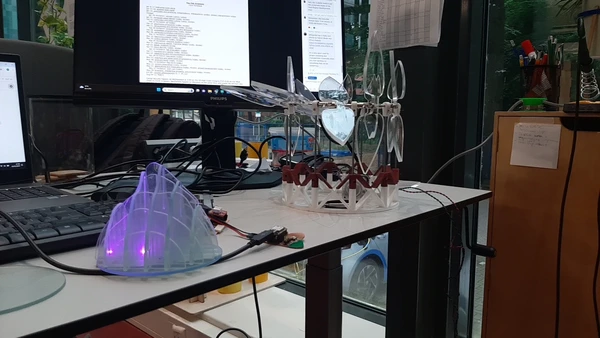
I test the mechanism with the flashlight of my phone again. I’m happy with the result.
Electronics
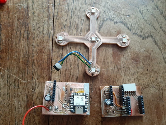
For my final project I designed and made 3 PCB’s. One for the pillow, the main PCB with the step stick driver and power supply and one for the neopixels. You can read about the design process below.
Stepresponse PCB
During week 11 I designed the first PCB for the stepresponse sensors. The finalproject PCB was the same as this PCB the only thing I changed is the layout to make it more compact. I did this during week 16. You can read about it there.
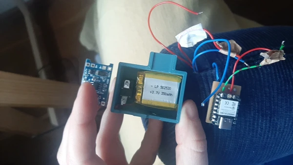
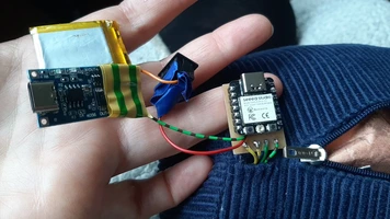
For creating the wireless connection I have to embed a battery and the battery manager. here you can read about me testing the XIAO ESP-C3 with a Lithium battery. I ordered the battery manager after this testing.
I finally got the battery charging module for the input pillow.
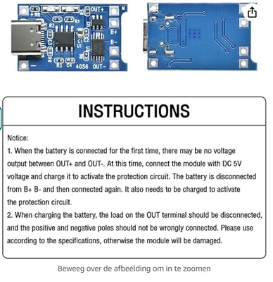
Before I connect the board I read about the instructions. here you can find the instruction video I watched on how to change the resistor on the battery manager to match the millie amps of the battery you are using. You need to do this to get the right charging speed for your battery.
I changed the resistor (R3) to 10k Ohm for charging the 130 mA lithium battery I’m using.
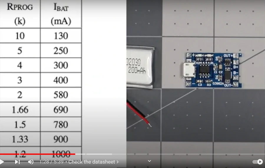
It’s been a struggle getting rid of the resistor and solder a new one since the components are super tiny (size 0402 SMD components). The trick is to hold the component with a plier and heat it with a heat gun and let gravity do the trick.
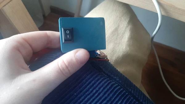
After swapping the resistor I check if the module is working properly by soldering and charging it. I see a red light and when it’s full it turns blue. I add the button for switching on and off the circuit and test the step response sending again. It’s working as I aspect.
Nightlight PCB
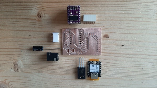
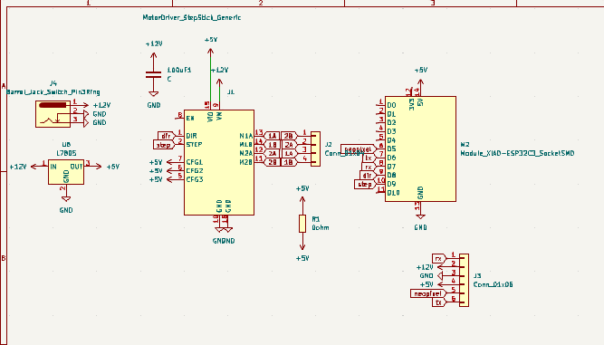
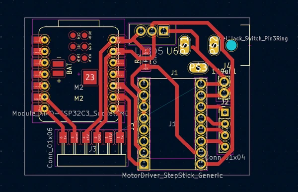
During week 13 I designed the first PCB for the nightlight that will have the power supply and drive the Stepper motor and neopixels. I have had a lot of trouble with this PCB. (5V to 3V, cracked traces, sloppy soldering because off how I orientated the parts) I made some changes and I made a second version. I did something stupid, I soldered the ESP32-C3 directly to the PCB board and got rid of the sockets. But I forgot to put tape between the boards.. I tried to remove the ESP with a heat gun but I could not properly have the PCB. So I made a third one.
Here you can have a look at the schematics
 And the components:
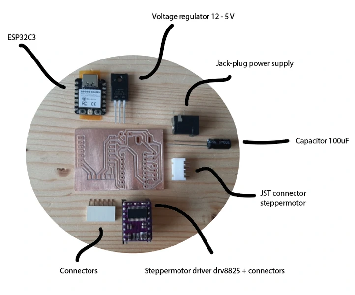
I have some side notes on the design.I would recommend adding a diode between the ESP-C3 power supply and the voltage regulator. I accidentally fried my step stick one time having both the power supply and the usb power on.. It will save you a lot of time debugging to trying to find out what’s wrong with the PCB.
Connectors that you will plug and unplug often you can better make though hole and solder on the back when you mill your own PCB’s with FR1 material. It prevents cracking traces. I have had so many problems with wiggling components cracking traces without me knowing. It can be hard to debug when this is happening when your coding. I actually would recommend ordering the PCB instead of FR1 when working with bigger components and connectors after my experience..
Here you can see my failed results:
Neopixel PCB
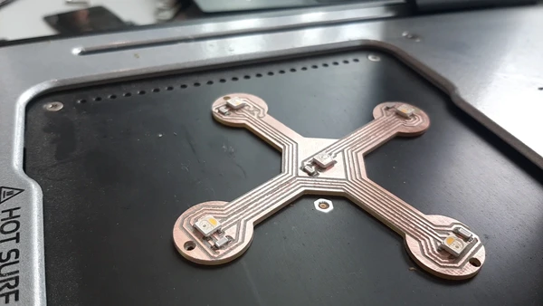
During week 14 I made the PCB for the neopixels. It’s a simple PCB but I love the shape and how it’s incorporated in my final project. I remade this PCB using RGBW neopixels in the last week because I want the light to be more warm and because the board I made in week 14 stopped working. Again the problem was a cracked trace but I did not notice until very late. So now I have a back-up PCB that I did not have to use.
Milling the PCB for the RGBW pixels:
![]() Result:
Result:
 Since I did not try reflow soldering until this point I tried it for the hard to solder neopixels. I used the vinyl cutter to make the mask for the solder paste inside coreldraw. I export the mask layer from KiCad to get the drawing of the pads.
 applying the solder together with my college Niels who was curious.
 We used the Voltera PCB printer to heat the board and reflow the solder paste. It came out looking very nice!
Coding
I start working on the code for the stepresponse during week 11 you can read about it there. During week 9 I worked on the stepper motor code, in week 13 I worked on wireless communication. I made a BLE connection. But I decided to go with ESP-NOW for myfinal project. Since then I have been working creating two code’s that combine the following.
Pillow code: Read the values of the stepresponse sensors, map the data, send data via ESP-NOW protocol.
Nightlight code: Receive the mapped sensor value’s. On receive change the motor speed to sensor data 1, change the neopixel brightness to sensor data 2. On no receive, turn the motor at the same speed and have one neopixel turned on with a breathing fading effect.
wireless connection with ESP-NOW
Since the BLE example I made during week 13 networking and communication stops working often and then I need to reset the system to get it to connect again, plus I didn’t really understand the code, I looked into ESP-NOW. Bas mentioned it briefly and so did my college Niels. It should be an easy set up and it will connect automatically when you turn on a device. Niels showed me how he has setup a connection before using the following sample.
So I tried it out myself. I Start with uploading the following code to the receiving ESP. In my case the nightlight. This code will display the MAC address of the ESP32-C3 I connect to it. In my case it’s
D4:F9:8D:04:1B:58
MAC address receiving code
// Complete Instructions to Get and Change ESP MAC Address: https://RandomNerdTutorials.com/get-change-esp32-esp8266-mac-address-arduino/

#include "WiFi.h"

void setup(){
  Serial.begin(115200);
  WiFi.mode(WIFI_MODE_STA);
  Serial.println(WiFi.macAddress());
}

void loop(){
  Serial.println(WiFi.macAddress());
}
Now upload the sending code, in my case the pillow. In the code I add the mac address of the receiving client. So it’s knows where to look. So I changed this line of code: uint8_t broadcastAddress[] = {0xFF, 0xFF, 0xFF, 0xFF, 0xFF, 0xFF};
and add the MAC address:
uint8_t broadcastAddress[] = {0xD4, 0xF9, 0x8D, 0x04, 0x1B, 0x58};
sending code, pillow
/*
  Rui Santos
  Complete project details at https://RandomNerdTutorials.com/esp-now-esp32-arduino-ide/

  Permission is hereby granted, free of charge, to any person obtaining a copy
  of this software and associated documentation files.

  The above copyright notice and this permission notice shall be included in all
  copies or substantial portions of the Software.
*/

#include <esp_now.h>
#include <WiFi.h>

// REPLACE WITH YOUR RECEIVER MAC Address
uint8_t broadcastAddress[] = {0xD4, 0xF9, 0x8D, 0x04, 0x1B, 0x58};

// Structure example to send data
// Must match the receiver structure
typedef struct struct_message {
  char a[32];
  int b;
 // float c;
 // bool d;
} struct_message;

// Create a struct_message called myData
struct_message myData;

esp_now_peer_info_t peerInfo;

// callback when data is sent
void OnDataSent(const uint8_t *mac_addr, esp_now_send_status_t status) {
  Serial.print("\r\nLast Packet Send Status:\t");
  Serial.println(status == ESP_NOW_SEND_SUCCESS ? "Delivery Success" : "Delivery Fail");
}

void setup() {
  // Init Serial Monitor
  Serial.begin(115200);

  // Set device as a Wi-Fi Station
  WiFi.mode(WIFI_STA);

  // Init ESP-NOW
  if (esp_now_init() != ESP_OK) {
    Serial.println("Error initializing ESP-NOW");
    return;
  }

  // Once ESPNow is successfully Init, we will register for Send CB to
  // get the status of Transmitted packet
  esp_now_register_send_cb(OnDataSent);

  // Register peer
  memcpy(peerInfo.peer_addr, broadcastAddress, 6);
  peerInfo.channel = 0;
  peerInfo.encrypt = false;

  // Add peer
  if (esp_now_add_peer(&peerInfo) != ESP_OK){
    Serial.println("Failed to add peer");
    return;
  }
}

void loop() {
  // Set values to send
  strcpy(myData.a, "THIS IS A CHAR");
  myData.b = random(1,20);
  //myData.c = 1.2;
  //myData.d = false;

  // Send message via ESP-NOW
  esp_err_t result = esp_now_send(broadcastAddress, (uint8_t *) &myData, sizeof(myData));

  if (result == ESP_OK) {
    Serial.println("Sent with success");
  }
  else {
    Serial.println("Error sending the data");
  }
  delay(2000);
}
receiving code, nightlight
/*
  Rui Santos
  Complete project details at https://RandomNerdTutorials.com/esp-now-esp32-arduino-ide/

  Permission is hereby granted, free of charge, to any person obtaining a copy
  of this software and associated documentation files.

  The above copyright notice and this permission notice shall be included in all
  copies or substantial portions of the Software.
*/

#include <esp_now.h>
#include <WiFi.h>

// Structure example to receive data
// Must match the sender structure
typedef struct struct_message {
    char a[32];
    int b;
  //  float c;
  //  bool d;
} struct_message;

// Create a struct_message called myData
struct_message myData;

// callback function that will be executed when data is received
void OnDataRecv(const uint8_t * mac, const uint8_t *incomingData, int len) {
  memcpy(&myData, incomingData, sizeof(myData));
  Serial.print("Bytes received: ");
  Serial.println(len);
  Serial.print("Char: ");
  Serial.println(myData.a);
  Serial.print("Int: ");
  Serial.println(myData.b);
  Serial.print("Float: ");
  //Serial.println(myData.c);
  //Serial.print("Bool: ");
  //Serial.println(myData.d);
  //Serial.println();
}

void setup() {
  // Initialize Serial Monitor
  Serial.begin(115200);

  // Set device as a Wi-Fi Station
  WiFi.mode(WIFI_STA);

  // Init ESP-NOW
  if (esp_now_init() != ESP_OK) {
    Serial.println("Error initializing ESP-NOW");
    return;
  }

  // Once ESPNow is successfully Init, we will register for recv CB to
  // get recv packer info
  esp_now_register_recv_cb(OnDataRecv);
}

void loop() {

}
I merged my stepresponse code with the ESP-NOW first sending 1 sensor integer. I decide to send the sensor value as an integer to do this I asked chat GPT how I convert a long int into an int because the sensor data is stored as a long int.
I get the following sample line of code:
long longValue = 123456;  // Example long value
int intValue = (int) longValue;  //
So I add it inside my own code:
  int intResult1 = (int) result1; // Convert long to int for sensor 1
  int intResult2 = (int) result2; // Convert long to int for sensor 2
and I send the data inside the struct myData.b:
myData.b = intResult1;
sending code with integers
/*
  Rui Santos
  Complete project details at https://RandomNerdTutorials.com/esp-now-esp32-arduino-ide/

  Permission is hereby granted, free of charge, to any person obtaining a copy
  of this software and associated documentation files.

  The above copyright notice and this permission notice shall be included in all
  copies or substantial portions of the Software.
  tx_rx03  Robert Hart Mar 2019.
  https://roberthart56.github.io/SCFAB/SC_lab/Sensors/tx_rx_sensors/index.html

  Modified by Adrián Torres Omaña
  Fab Academy 2023 - Fab Lab León
  Step Response TX, RX
  Fab-Xiao
  Modified by ChATGPT and Vera Schepers to make a double reading
*/

#include <esp_now.h>
#include <WiFi.h>


// REPLACE WITH YOUR RECEIVER MAC Address
uint8_t broadcastAddress[] = {0xD4, 0xF9, 0x8D, 0x04, 0x1B, 0x58};

// Structure example to send data
// Must match the receiver structure
typedef struct struct_message {
  char a[32];
  int b;
 // float c;
 // bool d;
} struct_message;

// Create a struct_message called myData
struct_message myData;

esp_now_peer_info_t peerInfo;


//stepresponse
long result1;   //variable for the result of the tx_rx measurement for sensor 1
long result2;   //variable for the result of the tx_rx measurement for sensor 2
int analog_pin1 = A0; //  GPIO 27 of the XIAO RP2040 or ESP32-C3 pin A0 for sensor 1
int analog_pin2 = A2; //  GPIO 27 of the XIAO RP2040 or ESP32-C3 pin A2 for sensor 2
int tx_pin1 = D1;  //     GPIO 28 of the XIAO RP2040 or ESP32-C3 pin D1 for sensor 1
int tx_pin2 = D3;  //     GPIO 28 of the XIAO RP2040 or ESP32-C3 pin D3 for sensor 2

// callback when data is sent
void OnDataSent(const uint8_t *mac_addr, esp_now_send_status_t status) {
  Serial.print("\r\nLast Packet Send Status:\t");
  Serial.println(status == ESP_NOW_SEND_SUCCESS ? "Delivery Success" : "Delivery Fail");
}

void setup() {
  // Init Serial Monitor
  Serial.begin(115200);

  // Set device as a Wi-Fi Station
  WiFi.mode(WIFI_STA);

  //stepresponse
  pinMode(tx_pin1, OUTPUT);      // Pin D1 provides the voltage step for sensor 1
  pinMode(tx_pin2, OUTPUT);      // Pin D3 provides the voltage step for sensor 2
  Serial.begin(115200);

  // Init ESP-NOW
  if (esp_now_init() != ESP_OK) {
    Serial.println("Error initializing ESP-NOW");
    return;
  }

  // Once ESPNow is successfully Init, we will register for Send CB to
  // get the status of Transmitted packet
  esp_now_register_send_cb(OnDataSent);

  // Register peer
  memcpy(peerInfo.peer_addr, broadcastAddress, 6);
  peerInfo.channel = 0;
  peerInfo.encrypt = false;

  // Add peer
  if (esp_now_add_peer(&peerInfo) != ESP_OK){
    Serial.println("Failed to add peer");
    return;
  }
}
//stepresponse function
long tx_rx(int tx_pin, int analog_pin) {
  int read_high;
  int read_low;
  int diff;
  long int sum;
  int N_samples = 100;    // Number of samples to take. Larger number slows it down, but reduces scatter.

  sum = 0;

  for (int i = 0; i < N_samples; i++) {
    digitalWrite(tx_pin, HIGH);         // Step the voltage high on one conductor
    read_high = analogRead(analog_pin); // Measure response of the other conductor
    delayMicroseconds(100);             // Delay to reach steady state
    digitalWrite(tx_pin, LOW);          // Step the voltage to zero
    read_low = analogRead(analog_pin);  // Measure response again
    diff = read_high - read_low;        // Desired answer is the difference between high and low
    sum += diff;                        // Sum up N_samples of these measurements
  }
  return sum;
}

void loop() {
  //stepresponse
  result1 = tx_rx(tx_pin1, analog_pin1); // Measure response for sensor 1
  result2 = tx_rx(tx_pin2, analog_pin2); // Measure response for sensor 2
  result1 = map(result1, 12763, 14468, 0, 255); // Map the values for sensor 1
  result2 = map(result2, 10429, 23735, 0, 255); // Map the values for sensor 2

  int intResult1 = (int) result1; // Convert long to int for sensor 1
  int intResult2 = (int) result2; // Convert long to int for sensor 2

  Serial.print("Sensor 1: ");
  Serial.print(result1);
  Serial.print(" | Sensor 2: ");
  Serial.println(result2);
  delay(100);

  // Set values to send
  strcpy(myData.a, "THIS IS A CHAR");
  myData.b = intResult1;
  //myData.c = 1.2;
  //myData.d = false;

  // Send message via ESP-NOW
  esp_err_t result = esp_now_send(broadcastAddress, (uint8_t *) &myData, sizeof(myData));

  if (result == ESP_OK) {
    Serial.println("Sent with success");
  }
  else {
    Serial.println("Error sending the data");
  }
  delay(2000);
}
I test it and it worked, so I altered the code to sending two sensor and integers:
sending two integers (stepresponse data)
/*
  Rui Santos
  Complete project details at https://RandomNerdTutorials.com/esp-now-esp32-arduino-ide/

  Permission is hereby granted, free of charge, to any person obtaining a copy
  of this software and associated documentation files.

  The above copyright notice and this permission notice shall be included in all
  copies or substantial portions of the Software.
  tx_rx03  Robert Hart Mar 2019.
  https://roberthart56.github.io/SCFAB/SC_lab/Sensors/tx_rx_sensors/index.html

  Modified by Adrián Torres Omaña
  Fab Academy 2023 - Fab Lab León
  Step Response TX, RX
  Fab-Xiao
  Modified by ChATGPT and Vera Schepers to make a double reading
*/

#include <esp_now.h>
#include <WiFi.h>


// REPLACE WITH YOUR RECEIVER MAC Address
uint8_t broadcastAddress[] = {0xD4, 0xF9, 0x8D, 0x04, 0x1B, 0x58};

// Structure example to send data
// Must match the receiver structure
typedef struct struct_message {
  char a[32];
  int b;
  int c;
 // float c;
 // bool d;
} struct_message;

// Create a struct_message called myData
struct_message myData;

esp_now_peer_info_t peerInfo;


//stepresponse
long result1;   //variable for the result of the tx_rx measurement for sensor 1
long result2;   //variable for the result of the tx_rx measurement for sensor 2
int analog_pin1 = A0; //  GPIO 27 of the XIAO RP2040 or ESP32-C3 pin A0 for sensor 1
int analog_pin2 = A2; //  GPIO 27 of the XIAO RP2040 or ESP32-C3 pin A2 for sensor 2
int tx_pin1 = D1;  //     GPIO 28 of the XIAO RP2040 or ESP32-C3 pin D1 for sensor 1
int tx_pin2 = D3;  //     GPIO 28 of the XIAO RP2040 or ESP32-C3 pin D3 for sensor 2

// callback when data is sent
void OnDataSent(const uint8_t *mac_addr, esp_now_send_status_t status) {
  Serial.print("\r\nLast Packet Send Status:\t");
  Serial.println(status == ESP_NOW_SEND_SUCCESS ? "Delivery Success" : "Delivery Fail");
}

void setup() {
  // Init Serial Monitor
  Serial.begin(115200);

  // Set device as a Wi-Fi Station
  WiFi.mode(WIFI_STA);

  //stepresponse
  pinMode(tx_pin1, OUTPUT);      // Pin D1 provides the voltage step for sensor 1
  pinMode(tx_pin2, OUTPUT);      // Pin D3 provides the voltage step for sensor 2
  Serial.begin(115200);

  // Init ESP-NOW
  if (esp_now_init() != ESP_OK) {
    Serial.println("Error initializing ESP-NOW");
    return;
  }

  // Once ESPNow is successfully Init, we will register for Send CB to
  // get the status of Transmitted packet
  esp_now_register_send_cb(OnDataSent);

  // Register peer
  memcpy(peerInfo.peer_addr, broadcastAddress, 6);
  peerInfo.channel = 0;
  peerInfo.encrypt = false;

  // Add peer
  if (esp_now_add_peer(&peerInfo) != ESP_OK){
    Serial.println("Failed to add peer");
    return;
  }
}
//stepresponse function
long tx_rx(int tx_pin, int analog_pin) {
  int read_high;
  int read_low;
  int diff;
  long int sum;
  int N_samples = 100;    // Number of samples to take. Larger number slows it down, but reduces scatter.

  sum = 0;

  for (int i = 0; i < N_samples; i++) {
    digitalWrite(tx_pin, HIGH);         // Step the voltage high on one conductor
    read_high = analogRead(analog_pin); // Measure response of the other conductor
    delayMicroseconds(100);             // Delay to reach steady state
    digitalWrite(tx_pin, LOW);          // Step the voltage to zero
    read_low = analogRead(analog_pin);  // Measure response again
    diff = read_high - read_low;        // Desired answer is the difference between high and low
    sum += diff;                        // Sum up N_samples of these measurements
  }
  return sum;
}

void loop() {
  //stepresponse
  result1 = tx_rx(tx_pin1, analog_pin1); // Measure response for sensor 1
  result2 = tx_rx(tx_pin2, analog_pin2); // Measure response for sensor 2
  result1 = map(result1, 12763, 14468, 0, 255); // Map the values for sensor 1
  result2 = map(result2, 10429, 23735, 0, 255); // Map the values for sensor 2

  int intResult1 = (int) result1; // Convert long to int for sensor 1
  int intResult2 = (int) result2; // Convert long to int for sensor 2

  Serial.print("Sensor 1: ");
  Serial.print(result1);
  Serial.print(" | Sensor 2: ");
  Serial.println(result2);
  delay(100);

  // Set values to send
  strcpy(myData.a, "sensordata");
  myData.b = intResult1;
  myData.c = intResult2;

  // Send message via ESP-NOW
  esp_err_t result = esp_now_send(broadcastAddress, (uint8_t *) &myData, sizeof(myData));

  if (result == ESP_OK) {
    Serial.println("Sent with success");
  }
  else {
    Serial.println("Error sending the data");
  }
  delay(1000);
}
receiving two integers (stepresponse data)
/*
Rui Santos
Complete project details at https://RandomNerdTutorials.com/esp-now-esp32-arduino-ide/
Permission is hereby granted, free of charge, to any person obtaining a copy
of this software and associated documentation files.
The above copyright notice and this permission notice shall be included in all
copies or substantial portions of the Software.
*/
#include <esp_now.h>
#include <WiFi.h>
// Structure example to receive data
// Must match the sender structure
typedef struct struct_message {
char a[32];
int b;
int c;
} struct_message;
// Create a struct_message called myData
struct_message myData;
// callback function that will be executed when data is received
void OnDataRecv(const uint8_t * mac, const uint8_t *incomingData, int len) {
memcpy(&myData, incomingData, sizeof(myData));
Serial.print("Bytes received: ");
Serial.println(len);
Serial.print("Char: ");
Serial.println(myData.a);
Serial.print("Int: ");
Serial.println(myData.b);
Serial.print("Int: ");
Serial.println(myData.c);
}
void setup() {
// Initialize Serial Monitor
Serial.begin(115200);
// Set device as a Wi-Fi Station
WiFi.mode(WIFI_STA);
// Init ESP-NOW
if (esp_now_init() != ESP_OK) {
Serial.println("Error initializing ESP-NOW");
return;
}
// Once ESPNow is successfully Init, we will register for recv CB to
// get recv packer info
esp_now_register_recv_cb(OnDataRecv);
}
void loop() {
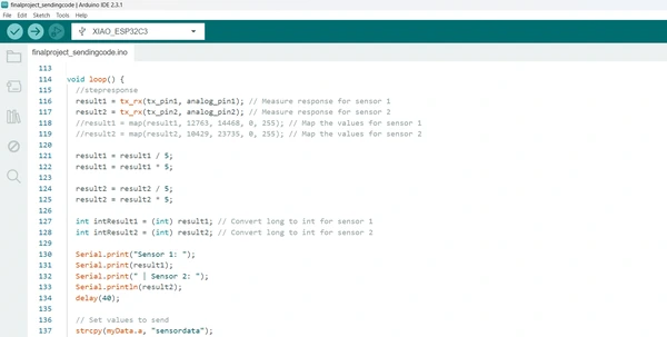
}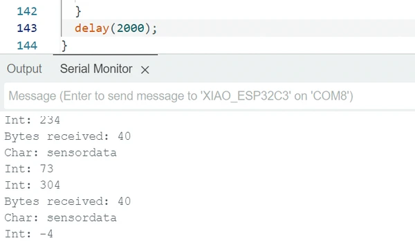 I played with the delays after testing to send the data quickly instead of every 2 seconds. But you can see I have to work on the mapping because I’m receiving negative sensor value’s.
Some helpful notes when starting working with ESP-NOW
- ESP-NOW is a wireless communication protocol defined by Espressif, which enables the direct, quick and low-power control of smart devices, without the need of a router. ESP-NOW can work with Wi-Fi and Bluetooth LE, and supports the ESP8266, ESP32, ESP32-S and ESP32-C series of SoCs. I personally find the code easy to understand which is a huge plus Inside the code you find a few important parts:
- typedef : define the type of data as a struct. you do this once
- struct_message variable that stores the data.
- Callback : function upon sending data – the OnDataSent function will be executed when a message is send
- Initialize: This is a function that will be executed when a message is received.
Mapping
The code for sending data via ESP works really nice. The only thing that’s left is to have a look at the sensor readings. I see I have a lot of spikes in my readings and it’s going to have an effect on the outputs. I read in Michelle’s documentation about
Smoothing values and I try the same trick of dividing and multiplying the value’s to remove spikes. Here you can see the code:
receiving two sensor data
#include <esp_now.h>
#include <WiFi.h>
#include <FastAccelStepper.h>

// Structure to receive data
typedef struct struct_message {
  char a[32];
  int b;
} struct_message;

struct_message incomingData;

// Stepper motor setup
#define dirPinStepper D8
#define stepPinStepper D9

FastAccelStepperEngine engine = FastAccelStepperEngine();
FastAccelStepper *stepper = NULL;
int motorSpeed = 200;
int microStepping = 32;

// Callback when data is received
void OnDataRecv(const uint8_t *mac, const uint8_t *data, int len) {
  memcpy(&incomingData, data, sizeof(incomingData));
  motorSpeed = map(incomingData.b, 0, 100, 50, 800);
  Serial.print("Received sensor value: ");
  Serial.println(incomingData.b);
  Serial.print("Mapped motor speed: ");
  Serial.println(motorSpeed);

  if (stepper) {
    stepper->setSpeedInHz(motorSpeed);
    stepper->applySpeedAcceleration();
  }
}

void setup() {
  Serial.begin(115200);
  WiFi.mode(WIFI_STA);

  if (esp_now_init() != ESP_OK) {
    Serial.println("Error initializing ESP-NOW");
    return;
  }

  esp_now_register_recv_cb(OnDataRecv);

  engine.init();
  stepper = engine.stepperConnectToPin(stepPinStepper);
  if (stepper) {
    stepper->setDirectionPin(dirPinStepper);
    stepper->setAutoEnable(true);
    stepper->setSpeedInHz(motorSpeed);
    stepper->setAcceleration(200 * microStepping);
    stepper->applySpeedAcceleration();
  }
}

void loop() {
  if (stepper) {
    stepper->runForward();
  }
}
This did an excellent job and really smooth out my sensor readings.
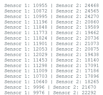 I did my best squeezing the pillow in everyway possible and read the highest and lowest number for both sensors. And I put the numbers in the map function. Note that the numbers are from a different sensors than the value’s screenshot above since I was still working on the pillow sensors.
result1 = map(result1, 12763, 14468, 0, 255); // Map the values for sensor 1
result2 = map(result2, 10429, 23735, 0, 255); // Map the values for sensor 2
I did notice over time that the mapped value’s change a bit. It’s mapping less neat right now than when I did this testing. I’m not sure why but for the future it would be better to add a reading of the sensor at the start of the code. Squeeze it the first sew seconds and use the reading as the highest and lowest value for the mapped value. I say Michelle’s project using this technique since she’s using different materials as sensors. Since mine is the same I thought it was not necessary.
Output devices, Steppermotor and neopixels
Neo pixels
During week 14 I started working on coding the neopixels. Since this was so easy I did not think it would be difficult to add the neopixels to the code at the end. I was very wrong about this, more about it later. But during the weeks I experimented with code for neo pixels and neostrips that you can find below.
Neopixels strip basics
//Fab Academy 2023 - Fab Lab León
//RGB LED
//Fab-Xiao
//original code from https://wiki.seeedstudio.com/XIAO-RP2040-with-Arduino/#rgb-led


#include <Adafruit_NeoPixel.h>

int PIN  = 2;
#define NUM_PIXELS 2

Adafruit_NeoPixel strip(NUM_PIXELS, PIN, NEO_GRB + NEO_KHZ800);


void setup() {
  strip.begin();
  strip.show(); // Initialize all pixels to 'off'
}

void loop() {
  // Example: Turn on the first pixel
  strip.clear(); // Clear the strip
  strip.setPixelColor(0, 255, 255, 255); // Set the first pixel color to white
  strip.setPixelColor(1, 255, 255, 255); // Set the first pixel color to white
  strip.show(); // Display the updated pixel
  delay(1000); // Delay for 1 second (adjust as needed)

}
Neopixels pixels basics
#include <Adafruit_NeoPixel.h>

int PIN  = D8;
#define NUM_PIXELS 2

Adafruit_NeoPixel strip(NUM_PIXELS, PIN, NEO_GRB + NEO_RGBW);


void setup() {
  strip.begin();
  strip.show(); // Initialize all pixels to 'off'
}

void loop() {
  // Example: Turn on the first pixel
  strip.clear(); // Clear the strip
  strip.setPixelColor(0, 255, 255, 255, 200); // Set the first pixel color to white
  strip.setPixelColor(1, 255, 255, 255, 30); // Set the first pixel color to white
  strip.show(); // Display the updated pixel
  delay(1000); // Delay for 1 second (adjust as needed)

}
Adafruit made a uber guide for Neopixels that if super helpful if you have troubleshere
Since I knew these codes worked It’s something I could fall back to when trouble shooting. If the device stopped working.
Steppermotor
During week 9 and week16 you can read about my struggles with microstepping and finding a library non interrupting for continuously rotation of a stepper motor. I used teh FastAccelStepper library to get the job done in week 16 but I still had problems with microstepping. Turns out most of my problems were hardware related. changing the driver again and changing the power supply for a more reliable one helped. The code I used during week 16 was fine. so I continued building on the code and combined it with the ESP-NOW sensor data with the help of Chat GPT to show me example code of using the mapped sensor value to set the motor speed in my previous code.
Microstepping and ESP-NOW
#include <esp_now.h>
#include <WiFi.h>
#include <FastAccelStepper.h>

// Structure to receive data
typedef struct struct_message {
  char a[32];
  int b;
} struct_message;

struct_message incomingData;

// Stepper motor setup
#define dirPinStepper D8
#define stepPinStepper D9

FastAccelStepperEngine engine = FastAccelStepperEngine();
FastAccelStepper *stepper = NULL;
int motorSpeed = 200;
//int microStepping = 32;

// Callback when data is received
void OnDataRecv(const uint8_t *mac, const uint8_t *data, int len) {
  memcpy(&incomingData, data, sizeof(incomingData));
  motorSpeed = map(incomingData.b, 0, 255, 50, 800);
  Serial.print("Received sensor value: ");
  Serial.println(incomingData.b);
  Serial.print("Mapped motor speed: ");
  Serial.println(motorSpeed);

  if (stepper) {
    stepper->setSpeedInHz(motorSpeed);
    stepper->applySpeedAcceleration();
  }
}

void setup() {
  Serial.begin(115200);
  WiFi.mode(WIFI_STA);

  if (esp_now_init() != ESP_OK) {
    Serial.println("Error initializing ESP-NOW");
    return;
  }

  esp_now_register_recv_cb(OnDataRecv);

  engine.init();
  stepper = engine.stepperConnectToPin(stepPinStepper);
  if (stepper) {
    stepper->setDirectionPin(dirPinStepper);
    stepper->setAutoEnable(true);
    stepper->setSpeedInHz(motorSpeed);
    stepper->setAcceleration(100);
    stepper->applySpeedAcceleration();
    stepper->runForward();
  }
}

void loop() {


}
Next up is to combine the neopixels in the code. I try to combine this fading neopixels sample that I tries outside of the ESP-NOW and stepper motor code first and that worked very nice.
dropdown
#include <Adafruit_NeoPixel.h>

#define PIN D5       // Pin where the NeoPixel strip is connected
#define NUMPIXELS 5    // Number of NeoPixels in the strip
#define BRIGHTNESS_STEPS 256  // Number of steps for brightness transition
#define FADE_DELAY 10   // Delay between steps in milliseconds

Adafruit_NeoPixel pixels(NUMPIXELS, PIN, NEO_GRBW + NEO_KHZ800);

// State variables
int pixelIndex = 0;
int brightness = 0;
bool increasing = true;
unsigned long lastUpdate = 0;

void setup() {
  pixels.begin();
  pixels.clear();
  Serial.begin(115200);      // Initialize serial communication at 115200 bits per second
}

void loop() {
  unsigned long currentTime = millis();
  if (currentTime - lastUpdate >= FADE_DELAY) {
    lastUpdate = currentTime;

    // Set the pixel brightness
    setPixelBrightness(pixelIndex, brightness);

    // Update brightness value
    if (increasing) {
      brightness++;
      if (brightness >= BRIGHTNESS_STEPS) {
        brightness = BRIGHTNESS_STEPS - 1;
        increasing = false;
      }
    } else {
      brightness--;
      if (brightness <= 0) {
        brightness = 0;
        increasing = true;
        pixelIndex = (pixelIndex + 1) % NUMPIXELS;
      }
    }
  }
}

void setPixelBrightness(int index, int brightness) {
  int value = map(brightness, 0, BRIGHTNESS_STEPS - 1, 0, 255);
  pixels.setPixelColor(index, pixels.Color(value, value, value, value)); // RGBW
  pixels.show();
}
And I tried to combine the two but the neopixels refused to glow. I run into a rabbit hole of debugging that got me to understand the ESP-NOw and stepper motor code is blocking the void loop, so it’s getting stuck somewhere. I kept thinking the problem was with the ESP-NOW and the neopixels but it turned out the fast Accel Stepper motor library and the neopixel library were the problem.
After lost of hours debugging I asked help from Niels. Together we thought the problem was within the ESP-NOw connection but there is little information to find about problems with this online. After more debugging we understood the problem is not the ESP-NOw it’s the stepper motor library! He helped me understand the Fast Accel library uses special hardware of the esp32 to be able to send the pulses very quickly. Making it able to accel smoothly. That’s why it’s called fast accel library. For sending the data the esp32 has two methods MCPWM and RMT. Unfortunately, the library only supports RMT for the ESP32-C3 specifically. This chip has two RMT channels. So we could use RMT0 for the motor and RMT1 for the Neopixels. We tried that, but it still didn’t work. MCPWM is not supported, so only bit banging remains. However, bit-banging at 800khz is exactly what the adafruit library does. However the neopixel bus bit bang method just seems to be written more efficiently than the neopixels library and is not clashing with the RMT timer. The only disadvantage is that it’s not considered an ideal method for neopixel bus and it therefore only works with low numbers of neopixels, fortunately it is not a problem for my project because I only need 5.
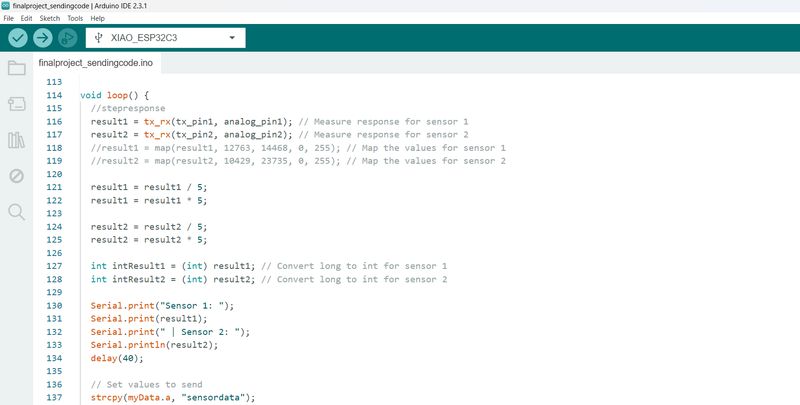
So I end up switching from the Adafruit Neopixel library to the Makuna’s NeoPixelBus library. This fixed the problems. I added the fading effect with a bit of help from chat gtp and combined al the codes in the following final project codes:
final project code sending device(pillow)
/*
  This code is gathered and altered by Vera Schepers with the help of chat GPT for the Fabacademy 2024 final project

  I used the ESP NOW sample code of:
  Rui Santos
  Complete project details at https://RandomNerdTutorials.com/esp-now-esp32-arduino-ide/

  Permission is hereby granted, free of charge, to any person obtaining a copy
  of this software and associated documentation files.

  The above copyright notice and this permission notice shall be included in all
  copies or substantial portions of the Software.
  tx_rx03  Robert Hart Mar 2019.
  https://roberthart56.github.io/SCFAB/SC_lab/Sensors/tx_rx_sensors/index.html

  And I used the Step Response TX, RX code
  Modified by Adrián Torres Omaña
  Fab Academy 2023 - Fab Lab León
  Fab-Xiao
*/

#include <esp_now.h>
#include <WiFi.h>


// REPLACE WITH YOUR RECEIVER MAC Address
uint8_t broadcastAddress[] = {0xD4, 0xF9, 0x8D, 0x04, 0x1B, 0x58};

// Structure example to send data
// Must match the receiver structure
typedef struct struct_message {
  char a[32];
  int b;
  int c;
 // float c;
 // bool d;
} struct_message;

// Create a struct_message called myData
struct_message myData;

esp_now_peer_info_t peerInfo;


//stepresponse
long result1;   //variable for the result of the tx_rx measurement for sensor 1
long result2;   //variable for the result of the tx_rx measurement for sensor 2
int analog_pin1 = A0; //  GPIO 27 of the XIAO RP2040 or ESP32-C3 pin A0 for sensor 1
int analog_pin2 = A2; //  GPIO 27 of the XIAO RP2040 or ESP32-C3 pin A2 for sensor 2
int tx_pin1 = D1;  //     GPIO 28 of the XIAO RP2040 or ESP32-C3 pin D1 for sensor 1
int tx_pin2 = D3;  //     GPIO 28 of the XIAO RP2040 or ESP32-C3 pin D3 for sensor 2

// callback when data is sent
void OnDataSent(const uint8_t *mac_addr, esp_now_send_status_t status) {
  Serial.print("\r\nLast Packet Send Status:\t");
  Serial.println(status == ESP_NOW_SEND_SUCCESS ? "Delivery Success" : "Delivery Fail");
}

void setup() {
  // Init Serial Monitor
  Serial.begin(115200);

  // Set device as a Wi-Fi Station
  WiFi.mode(WIFI_STA);

  //stepresponse
  pinMode(tx_pin1, OUTPUT);      // Pin D1 provides the voltage step for sensor 1
  pinMode(tx_pin2, OUTPUT);      // Pin D3 provides the voltage step for sensor 2
  Serial.begin(115200);

  // Init ESP-NOW
  if (esp_now_init() != ESP_OK) {
    Serial.println("Error initializing ESP-NOW");
    return;
  }

  // Once ESPNow is successfully Init, we will register for Send CB to
  // get the status of Transmitted packet
  esp_now_register_send_cb(OnDataSent);

  // Register peer
  memcpy(peerInfo.peer_addr, broadcastAddress, 6);
  peerInfo.channel = 0;
  peerInfo.encrypt = false;

  // Add peer
  if (esp_now_add_peer(&peerInfo) != ESP_OK){
    Serial.println("Failed to add peer");
    return;
  }
}
//stepresponse function
long tx_rx(int tx_pin, int analog_pin) {
  int read_high;
  int read_low;
  int diff;
  long int sum;
  int N_samples = 100;    // Number of samples to take. Larger number slows it down, but reduces scatter.

  sum = 0;

  for (int i = 0; i < N_samples; i++) {
    digitalWrite(tx_pin, HIGH);         // Step the voltage high on one conductor
    read_high = analogRead(analog_pin); // Measure response of the other conductor
    delayMicroseconds(100);             // Delay to reach steady state
    digitalWrite(tx_pin, LOW);          // Step the voltage to zero
    read_low = analogRead(analog_pin);  // Measure response again
    diff = read_high - read_low;        // Desired answer is the difference between high and low
    sum += diff;                        // Sum up N_samples of these measurements
  }
  return sum;
}

void loop() {
  //stepresponse
  result1 = tx_rx(tx_pin1, analog_pin1); // Measure response for sensor 1
  result2 = tx_rx(tx_pin2, analog_pin2); // Measure response for sensor 2
  result1 = map(result1, 12763, 14468, 0, 255); // Map the values for sensor 1
  result2 = map(result2, 10429, 23735, 0, 255); // Map the values for sensor 2

  result1 = result1 / 5; //smooth out sensor values
  result1 = result1 * 5; //smooth out sensor values

  result2 = result2 / 5; //smooth out sensor values
  result2 = result2 * 5; //smooth out sensor values

  int intResult1 = (int) result1; // Convert long to int for sensor 1
  int intResult2 = (int) result2; // Convert long to int for sensor 2

  // print the integers in the serial monitor
  Serial.print("Sensor 1: ");
  Serial.print(result1);
  Serial.print(" | Sensor 2: ");
  Serial.println(result2);
  delay(40);

  // Set values to send
  strcpy(myData.a, "sensordata");
  myData.b = intResult1;
  myData.c = intResult2;

  // Send message via ESP-NOW
  esp_err_t result = esp_now_send(broadcastAddress, (uint8_t *) &myData, sizeof(myData));

  if (result == ESP_OK) {
    Serial.println("Sent with success");
  }
  else {
    Serial.println("Error sending the data");
  }
  delay(200);
}
final project code receiving device(nightlight)
#include <esp_now.h>
#include <WiFi.h>
#include <NeoPixelBus.h>
#include <FastAccelStepper.h>

// IO pin assignments
#define dirPinStepper D8
#define stepPinStepper D9
#define ledPin D5

// Settings
#define numPixels 5    // Number of NeoPixels in the strip
#define brightSteps 256  // Number of steps for brightness transition

// Define the color components
uint8_t red;
uint8_t green;
uint8_t blue;
uint8_t white; // Add white component
RgbColor black(0);

// Structure to receive data
typedef struct struct_message {
  char a[32];
  int b;
  int c;
} struct_message;
struct_message incomingData;

// Initialize NeoPixelBus object
NeoPixelBus<NeoRgbwFeature, NeoEsp32BitBang800KbpsMethod> pixels(numPixels, ledPin);

FastAccelStepperEngine engine = FastAccelStepperEngine(); // motor
FastAccelStepper *stepper = NULL; // motor

// State variables
int pixelIndex = 0;
int brightness = 0;
int motorSpeed = 200;
bool fadeIn = true;
unsigned long previousMillis = 0;
const long interval = 80; // interval at which to update the LED
unsigned long lastMessage;
const long connectionLost = 2000;

// Callback when data is received
void OnDataRecv(const uint8_t *mac, const uint8_t *data, int len) {
  memcpy(&incomingData, data, sizeof(incomingData));
  motorSpeed = map(incomingData.b, 0, 100, 50, 400);
  lastMessage = millis();
  Serial.print("Received sensor value: ");
  blue = incomingData.c;
  Serial.println(incomingData.b);
  Serial.print("Mapped motor speed: ");
  Serial.println(motorSpeed);

  if (stepper) {
    stepper->setSpeedInHz(motorSpeed);
    stepper->applySpeedAcceleration();
  }

  // Set brightness of NeoPixels 0 to 3 based on sensor data
  int sensorBrightness = map(incomingData.c, 0, 400, 0, 180);
  for (int i = 0; i < 4; i++) {
    pixels.SetPixelColor(i, RgbwColor(0, 0, sensorBrightness, sensorBrightness)); // Set blue color with sensor-based brightness
  }
  pixels.Show();
}

void setup() {
  Serial.begin(115200);
  WiFi.mode(WIFI_STA);

  if (esp_now_init() != ESP_OK) {
    Serial.println("Error initializing ESP-NOW");
    return;
  }

  esp_now_register_recv_cb(OnDataRecv);

  pixels.Begin(); // Initialize NeoPixels

  Serial.begin(115200);
  delay(2000); // Wait for serial monitor
  Serial.println("Hello World");
  // Set the color components to a desired value (for example, red)
  red = 0;
  green = 0;
  blue = 255;
  white = 100; // Set white to zero initially

  // Set up stepper motor
  engine.init(); // start stepper engine object
  stepper = engine.stepperConnectToPin(stepPinStepper);
  if (stepper) {
    stepper->setDirectionPin(dirPinStepper);
    stepper->setAutoEnable(true);
    stepper->setSpeedInHz(motorSpeed);
    stepper->setAcceleration(3000);
    stepper->applySpeedAcceleration();
    stepper->runForward();
  }
}

void loop() {
  // Non-blocking smooth fading for NeoPixel 4
  unsigned long currentMillis = millis();

  if (currentMillis - lastMessage >= connectionLost ) {
    pixels.SetPixelColor(0, black);
    pixels.SetPixelColor(1, black);
    pixels.SetPixelColor(2, black);
    pixels.SetPixelColor(3, black);
  }

  if (currentMillis - previousMillis >= interval) {
    previousMillis = currentMillis;

    if (fadeIn) {
      brightness += 4; // Increase brightness
      if (brightness >= 255) {
        brightness = 255;
        fadeIn = false; // Switch to fade out
      }
    } else {
      brightness -= 4; // Decrease brightness
      if (brightness <= 10) {
        brightness =10;
        fadeIn = true; // Switch to fade in
      }
    }

    // Set NeoPixel 4 to the current brightness level
     pixels.SetPixelColor(4, RgbwColor(0, 0, 0, brightness)); // Set white color with current brightness
    pixels.Show();
  }

  // Other code can run here without being blocked
}
Design files
PCB files
3D printing files
- download the STL and STEP file of the base and the stepper motor holder here
- download the STL and STEP file of the bearing holdershere
- download the STL and STEP file of electronic case for the pillow here
lasercut files
- download the DXF file of the acrylic leafs shapes here
- download the DXF file of the lid for the night light base here
Reflecting
I learned a lot during this course on personal level. The course was outside of my comfort zone and the first week being the only one without an engineering background, and after hearing a lot of new terms about communication protocols which made 0 sense, I was a bit worried what I got myself into. But I’m not one to back off and I know I can sink my teeth into something. I learned to prioritize tasks during the week because of the strict deadlines, I made schedules and the only tip I can give is just start the tasks, even when it’s 15 minutes on the train, the last hour before you go to sleep, just start doing something, document, looks into something, start your assignments! And don’t think about it to much, one thing will led to another! Some weeks were hard and I found help from my colleague’s and peers and instructors. I could not have done this corse without this network of supporting people. I remember during the first week Erwin helped me out on a friday night at 12, when I messed up my repository. His help gave me such a release! I would say to others don’t be afraid to ask help when you need it!
I’m proud to say I learned a lot about electronics and programming, I’m more confident about the subject which was my biggest goal. I feel like I learned a base to be able to teach myself. I learned what to look for, finding similar projects and what components I can use to make something. And I already am using this knowledge in my jobs so I’m really happy about this. Sure sometimes I got absolutely crazy stressed about why things (especially stepper motors) stopped working but I aslo learned it’s part of electronics design. I find humor in the meme channel and the stories of others having the same troubles. This helped me to continue trying and trying! I do recommend to stop trying at a certain point. Try doing something else for a bit or take a break when your completely stuck, because it’s likely your missing the obvious things because of a foggy mind. I can tell from experience. I will take this with me, it does not only applies to working with electronics.
A little practical thing for whoever is thinking about following this course. I wished I organized my files, pictures and video’s better from the start. It’s a mess right now! And it takes me some time to find the right file type and photo for finishing my documentation, try to find a system for it that works finding the file you need even after 8 weeks has past.
At last I would say the biggest thing this program has given me is time for myself. That mind sound weird because there was always to little hours in the week. But I’m talking about time to learn new things and time to actually realizing idea’s in my head. Having my schedule blocked for this purpose was an absolute blessing. It brought me back to when I was studying at the art academy and it made me realize how much I missed getting challenged like this. I need to be in an environment and mindset for this and Waag did this for me, so thank you all!
And for those who made it to the end of the page, thank you for reading! :D