Greetings! Welcome to the Third week of FabAcademy.
"In this week, our objective is to successfully accomplish two assignments centered around Computerized Controlled Cutting.
The assignments are categorized into a group task and an individual task, each contributing distinct elements to the overall learning experience.
The primary focus of these assignments is to document my insights and acquired knowledge in computer-controlled cutting, encompassing both laser cutting and vinyl cutting techniques.
The main aspect of this documentation involves illustrating my utilization of laser cutting to craft a personalized construction kit.
Additionally, I am detailing my understanding of parametric design and its significance in the context of laser cutting.
Group Assignment Laser Cutting and Scanning
During this week's group assignment, our focus was on Laser cutting and scanning. We worked in team to explore and conduct trials on the laser cutting machine. The primary objectives of the group assignment were as follows:
Understanding the Laser Cutting Machine:
Comprehensive exploration of the laser cutting machine and its specifications.
Gaining insights into the technical details and capabilities of the machine.
Operational Knowledge:
Acquiring practical knowledge on how to operate the laser cutting machine effectively.
Learning the step-by-step process of setting up and running the machine.
Safety Precautions:
Understanding and implementing safety measures associated with operating the Laser Cutting Machine.
Emphasizing the importance of maintaining a secure working environment.
Optimization Parameters:
Determining the optimum speed and power values for the laser cutting machine.
Calculating the Kerf value, a crucial parameter for achieving precision in cutting, across various materials.
These optimized values now serve as valuable references for our individual assignments and projects. Having established the optimal speed, power, and Kerf values, we can parametrically modify our CAD models based on these findings.
Laser Cutter
A laser cutter is a computer-controlled device that utilizes a laser beam to precisely cut or engrave materials.
It works by directing the focused laser beam onto the surface of the material, which then either melts, burns, or vaporizes the material,
leaving a clean and accurate cut. Laser cutters are versatile tools commonly used in various industries, including manufacturing,
crafting, and prototyping. They can cut through a wide range of materials such as wood, acrylic, plastic, fabric, and metal, depending
on the laser's power and the material's compatibility. Laser cutting is valued for its precision, speed, and ability to produce intricate
designs, making it a popular choice for creating detailed patterns, prototypes, and customized products.
At our Vigyan Ashram Fablab, we are having a C02 Laser Cutter, so we have did a trail and experimenting on the same.
C02 Laser Cutter Machine
A CO2 laser engraving and cutting machine is a versatile tool used for engraving and cutting various materials using a high-powered laser beam.
The “CO2” in the name refers to the type of laser it uses, which generates the laser beam by exciting carbon dioxide gas.
This cutting-edge technology employs a sealed carbon dioxide gas mixture as its laser medium, generating a focused and powerful beam of infrared light.
The CO2 laser cutter is particularly adept at slicing through materials like wood, acrylic, leather, and certain metals with exceptional accuracy,
leaving clean edges and intricate designs. Its effectiveness lies in its ability to vaporize or melt the material in its path, making it suitable
for a wide range of applications, from crafting intricate designs to industrial manufacturing processes. The machine's user-friendly interface and
computer-controlled precision make it an indispensable tool for professionals and hobbyists alike, revolutionizing the way materials are shaped and customized.
Parametric design, a fundamental aspect of computer-aided design (CAD) software, offers a powerful toolset that significantly enhances efficiency by eliminating the need for manual redesign when altering design dimensions. This innovative approach allows design engineers to establish relationships among various attributes, ensuring that modifications to one dimension automatically propagate throughout the entire design. In essence, parametric modeling empowers designers to define entire classes of shapes, providing flexibility beyond specific instances.
The relevance of parametric modeling becomes particularly evident in laser cutting operations, where precision is paramount. Addressing the kerf in laser cutting, which necessitates adjustments in design elements such as slots for press fits, underscores the importance of parametric modeling. Slot dimensions are contingent upon variables like material thickness and kerf, both subject to change based on factors like material type, speed, power settings, and more. Rather than manually adjusting each dimension, parametric modeling enables the designer to dynamically link the slot width to material thickness and kerf.
In the context of laser cutting, where the need for precise slot dimensions is critical, mastering parametric modeling becomes an essential skill. This is exemplified through practical application in software like Fusion 360.
Parametric Modeling in Fusion 360:
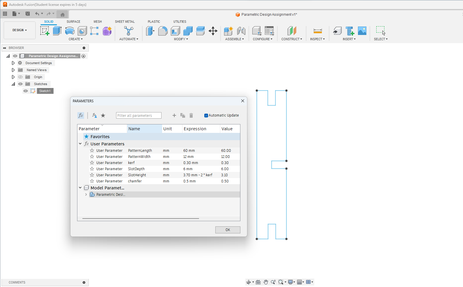
Initiated the parametric design process by creating a rectangular shape with slots along its periphery in Fusion 360.
Defined parametric equations within the "Modify" and "Change Parameters" menu to establish a dynamic relationship between slot width, material thickness, and kerf.
Utilized the parameters table to introduce equations that considered the interplay of material thickness and kerf in determining slot dimensions.
Explored the flexibility of the parametric model by modifying the material thickness through the "Modify Equation" menu. Witnessed the seamless adjustment of all slot width dimensions with a simple alteration in the parametric equation table.
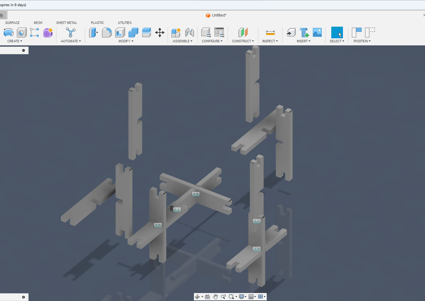
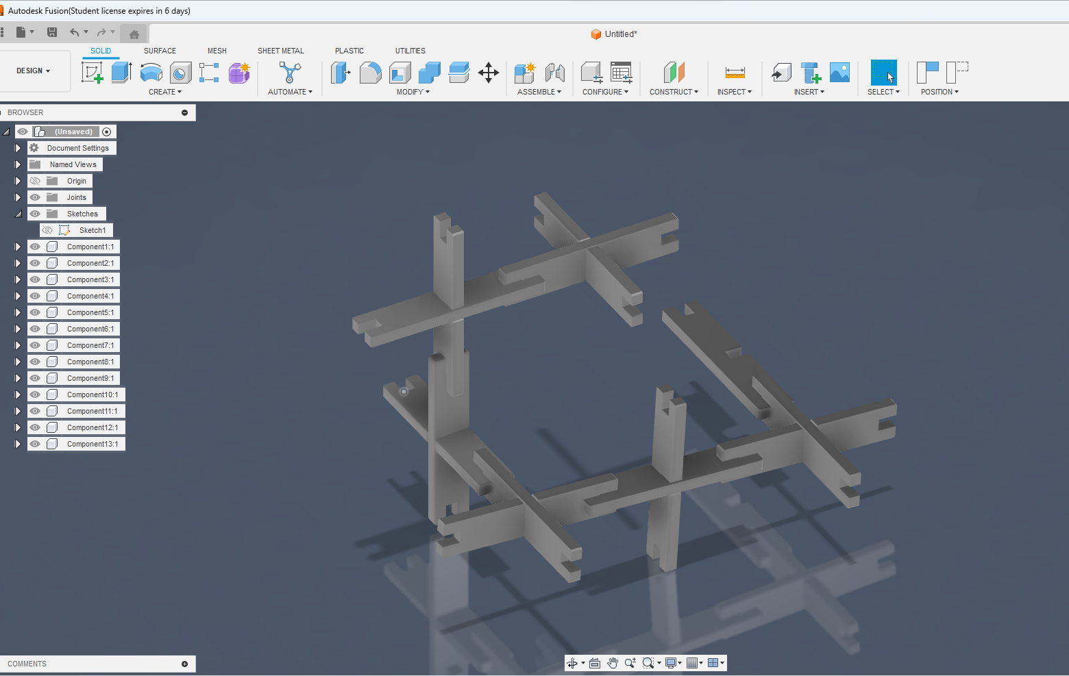
Model Assembly in Fusion 360:
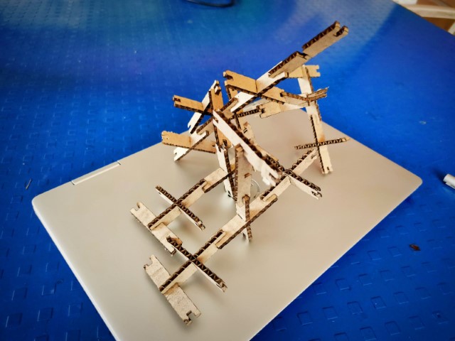
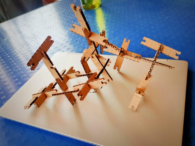
Actual Cutting and Joints
By incorporating parametric modeling into the design workflow, the ability to swiftly adapt to changes in material properties, laser cutting settings, and other parameters becomes a reality. This not only enhances efficiency but also ensures precision and accuracy in the final laser-cut components. Parametric modeling in Fusion 360 emerges as a valuable skill, offering a time-saving and versatile approach to design iteration and optimization.
Observation from actual Cutting
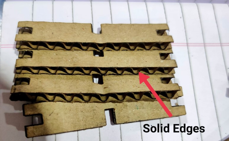
Observation of Cutting Cardboard: During laser cutting on corrugated cardboard sheets, I have noted a distinct difference in the outcomes based on the orientation of the cardboard.
When the sheet is placed vertically, the laser cutting tends to cause the flutes to open up. However, when the cardboard sheet is positioned horizontally, a more favorable result is achieved, with the laser creating cross cuts that maintain the integrity of the flutes.
This observation suggests that horizontal placement is preferable for achieving the desired cutting outcome on corrugated cardboard.
Vinyl Cutter
A vinyl cutter serves as an ideal entry-level device for crafting signs. It operates by directly cutting computer-designed vector files containing patterns
and letters onto a roll of vinyl. The vinyl, mounted and fed into the cutter, is connected to the computer via a USB or serial cable.
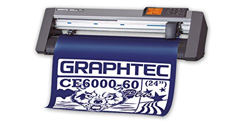
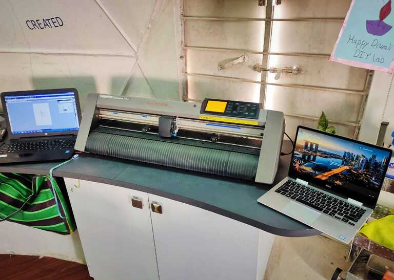
Fablab VA Vinyl Cutter Deatils
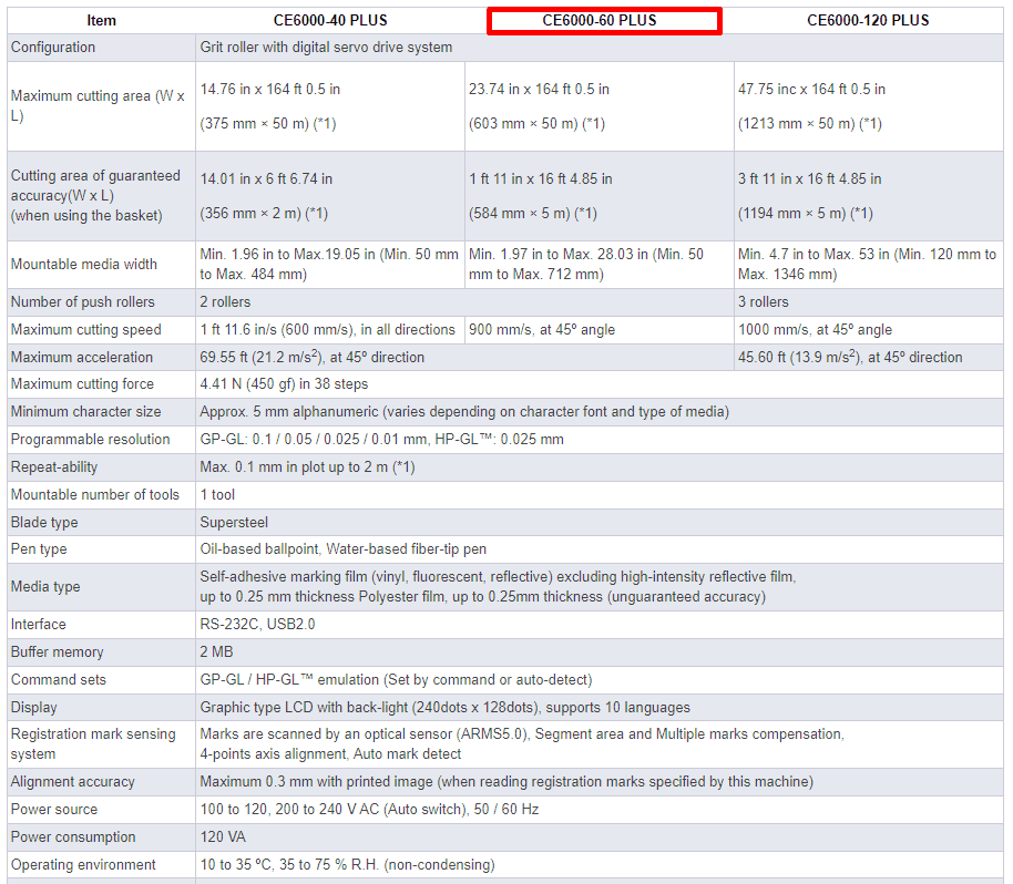
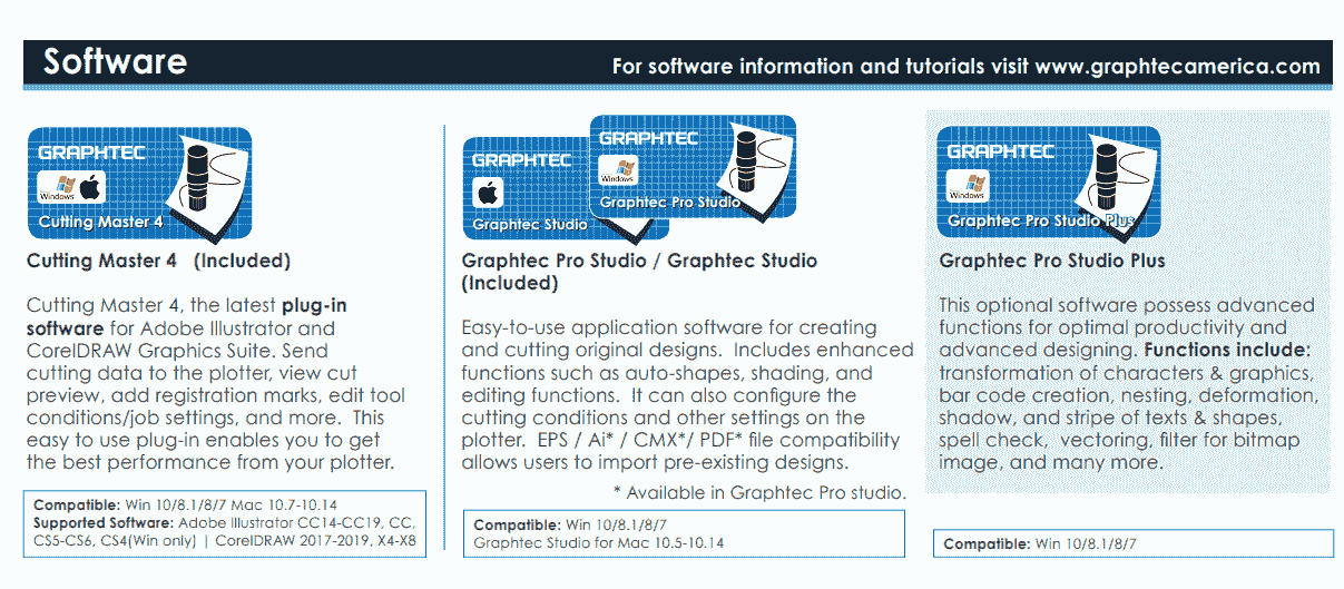
Graphtec CE6000-60 Plus series Vinyl Cutter
The CE6000 series sets the standard for high performance, low cost cutting plotters.
It is equipped with professional-level features such as registration mark sensing and perforation
cutting for producing a dividing line of labels or packaging mock-ups. The Graphtec CE6000 Plus Series comes standard with: floor stands
(except for the 15" CE-6000-60 model comes with rear media roll rack), Cutting Master Plug-in, plus Graphtec's ARMS (Automatic Registration Mark Sensor) system.
Key Features:-
Reliable cutting quality for variety applications
Intuitive and easy operation
Improved application software
Includes Graphtec ARMS (Advanced Registration Mark Sensor)
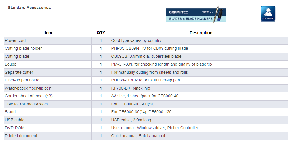
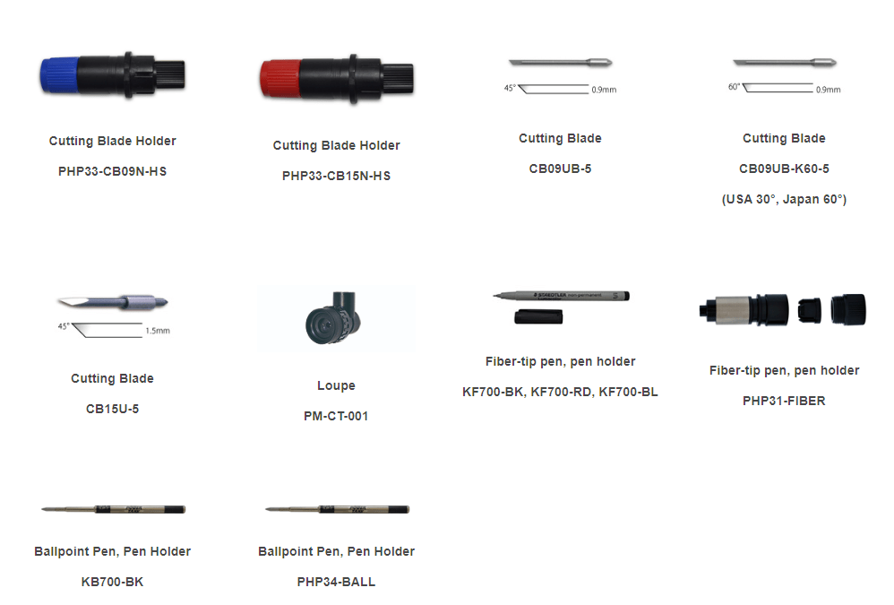
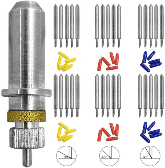
There various neccessary accesories available with the Graphtec Cutting Plotter. The Main component are the Cutting Blade which are being used for cutting various material.
About Cutting Blades:-
30 deg blade: Used for very thin material.
45 deg blade: Used for general vinyl cutter.
60 deg blade: Suitable for thick material like OFC sheet, copper sheet, mirror sheet.etc
Source: Signwarehouse
I have observed and studied about different Blade Angles there use and blade settings.
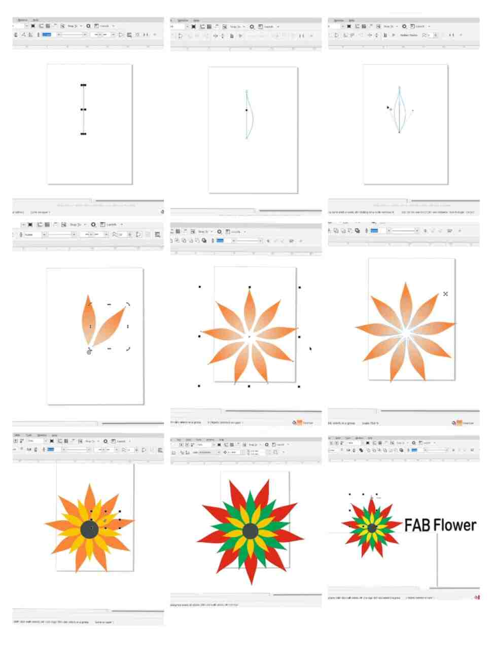
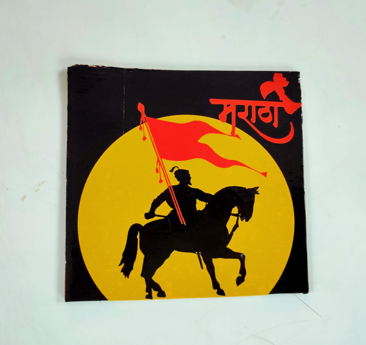
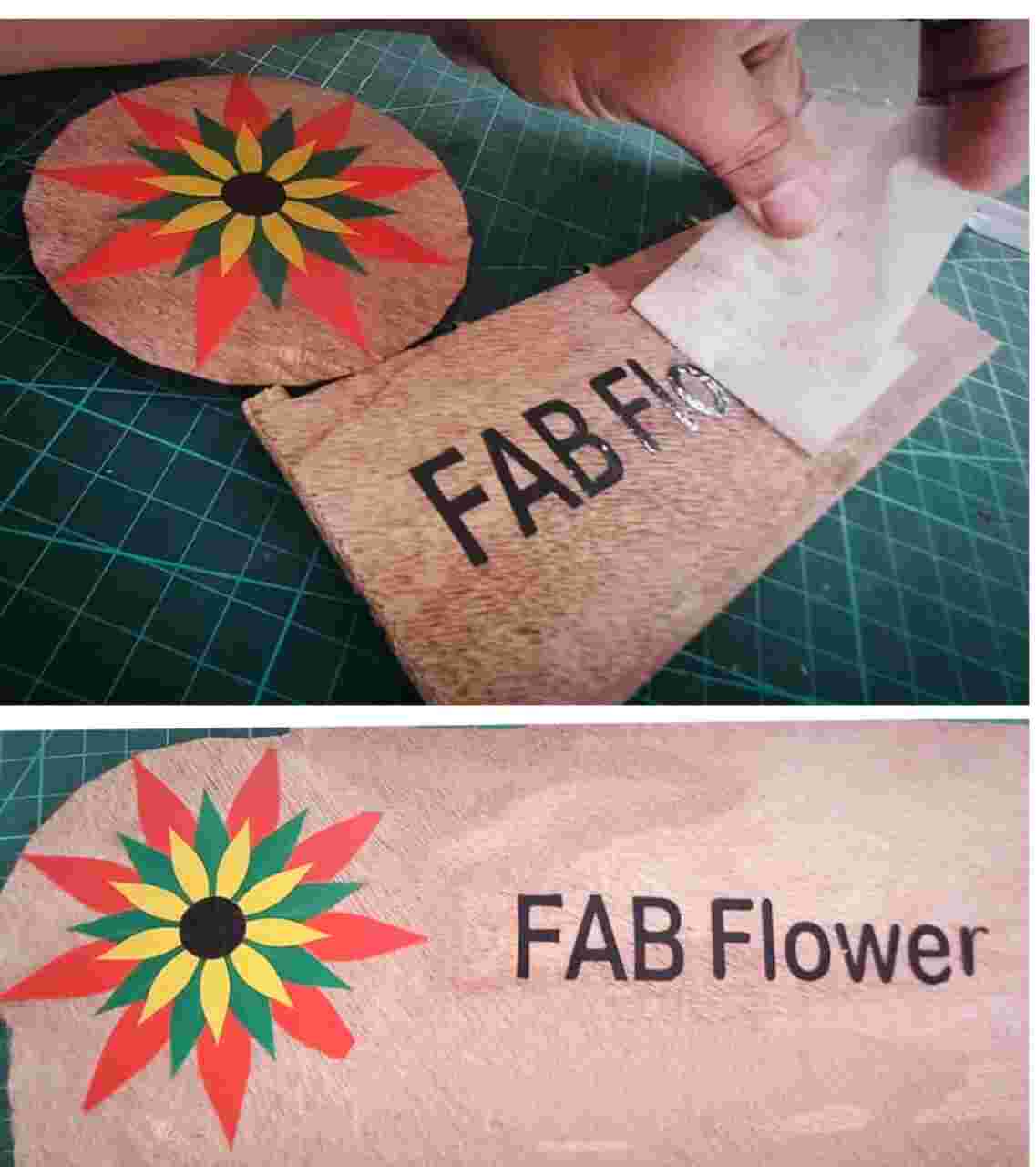
Creating a Design and Cutting of Vinyl Plotter
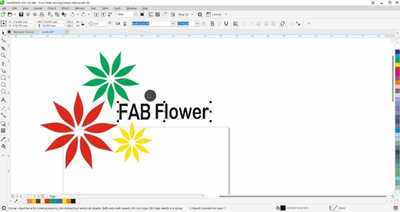
In the last assignment on 2D Design I have used Corel Draw and Inkskape to create 2D design file for cutting.
In Corel Draw I have Created my own design with marking lines and create a Flower shape by using various comands.
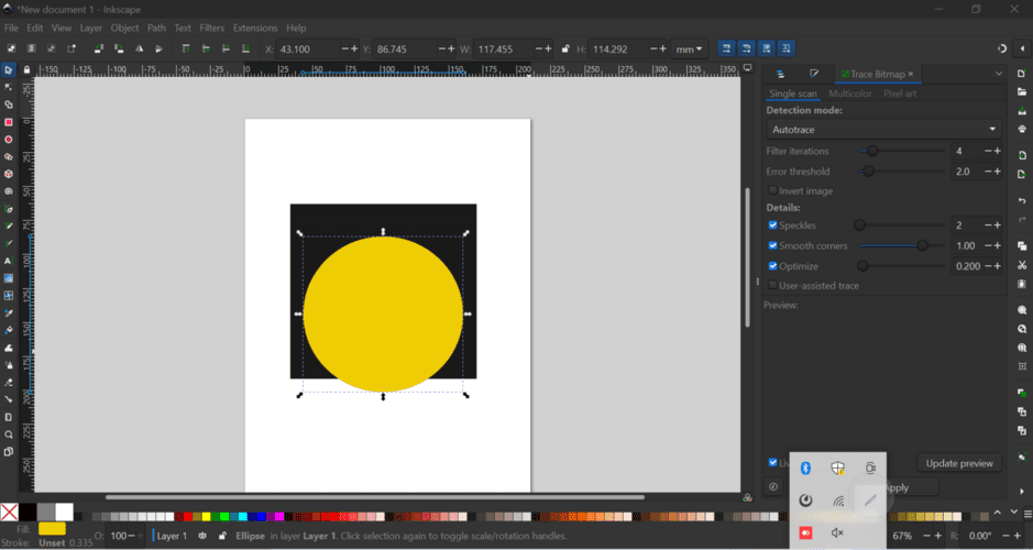
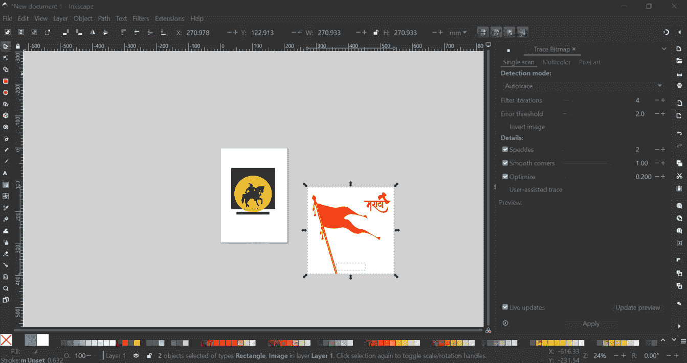
I have also tried to design a Sticker by trace bitmap the vector image and creating a drwaing file
Exporting the design file into DXF format
To import any file in the cutting software of the Plotter machine we need some desired file extension. I have exported the file to DXF format.
Cutting Software
This machine supports Graphtec Studio software for sending cutting file to Plotter Machine
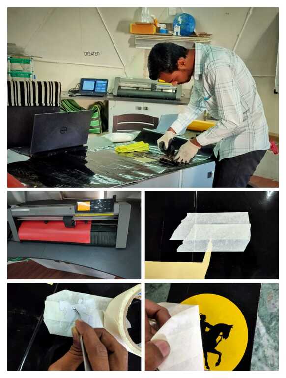
Cutting the design on Vinyl Paper
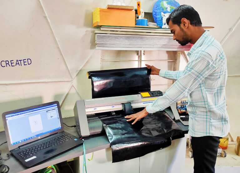
After the software is loaded with the cutting file, lets start the machine to load the material and and proceed with cutting
Step 1: Switch On the Machine and Wait till the machine initialize the settings
Step 2: Now push down the lever at backside of the machine to insert and load the Vinyl Paper
Load the paper facing the colour vinyl paper on the top and the peel off white paper at bottom
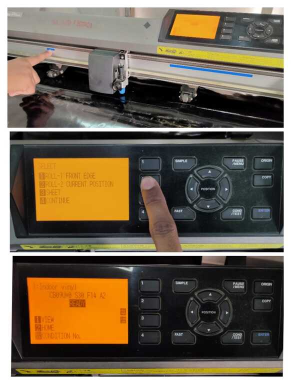
Step 3: After the material is loaded properly pull up lever to fix the paper on the bed
Step 4: Now use the Arrows Keys on the control panel to move the Cutting Head and set the origin at any desired point on the cutting area.
Step 5: Give the cutting command and take out the vinyl paper once it is finished.