Week 16
System Integration
Brief Overview
System integration is the process of linking together different computing systems and software applications physically or functionally, to act as a coordinated whole. The goal of system integration is to ensure that all sub-systems function together seamlessly, improving overall efficiency, data consistency, and reducing operational costs. In this assignment, I had documented system integration process workflow and production method for my Final Project.
Individual Assignment:-
In this assignment:-
1.System Integration of project componets and process.
2.Create a flowchart, explain the integration and Document what I have learned.
About my Final Project:-
A compact 2 axis CNC lathe, with totally enclosed interlocking guards - the ideal introduction to small part CNC manufacture. Variable spindle speeds and feedrates make the MicroTurn ideal for cutting resistant materials such as wax, plastic, acrylic, aluminum and free cutting alloys.
To Know more about my Final Project visit Here
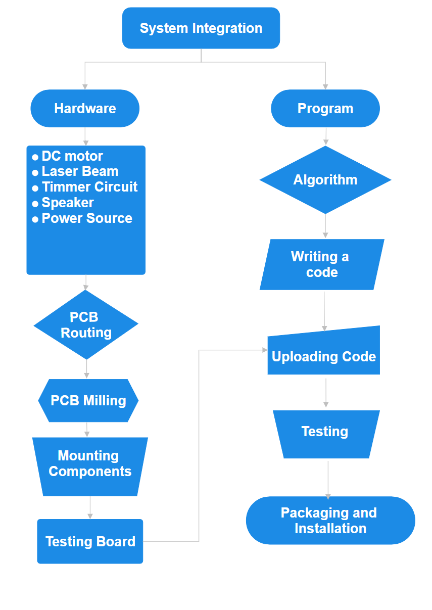
System Integration:
Work Flowchart:-
In my project I have utilize most of the machine and equipments available in our Vigyan Ashram Fablab. So I have split the work in two horizontals, Hardware and Program.
- What will it do?
- Who has done what beforehand?
- What will you design?
- What materials and components will be used?
- Where will they come from?
- How much will they cost?
- What parts and systems will be made?
- What processes will be used?
- What questions need to be answered?
- How will it be evaluated?
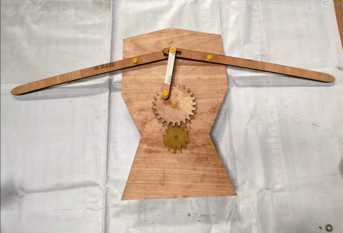
- SliderCrank mechanism for the Motion of hands for scarecrow.
- Scarecrow body structure which holds the mechanism
- Controller board, Integrated circuit to control the hand motion and loud sound.
- 2D and 3D design which will include additive and subtractive manufacturing
- Laser Cutting process
- Electronics design and programming
- Use of the PCB Milling machines at the lab to produce electronic board.
- Welding and Fabrication for making a stand for scarecrow.
- Insert an SD card into the microphone's SD card slot. The card should contain various scary sound clips like gunshots, tiger roars, and eagle calls.
- Ensure there is a delay between sounds in the audio clips to prevent continuous playback and to conserve battery life.
- If the loudspeaker is not playing sounds, check the SD card for correct file format and proper insertion.
- Ensure all electrical connections are secure and the control module is functioning properly.
- Verify the battery is charged and properly connected.
- Economical Timer: To control the scarecrow’s movements.
- Economical Sound System: For our product.
Objectives
What will it do?
So basically the main motive of making this Smart scarecrow it to, create a automated humaniod structural scary Farm field gaurd. This Smart Scarecrow will be used to make scary sounds and make hand motions.
What will you design?
I will design a mechanism for automation of the scarecrow. I will also design a microcontroller board to control the operations of the system and also some 3D printed parts for mounting and packaging. I have designed and cutted parts on Laser cutter as well.
What materials and components will be used?
To create a Smart Scarecrow: Material required can be refered from BOM list
Where will they come from?
Hardware like Motor, Battery, Solar Panel and Fabrication material will be procured from local vendors, and electronics material like SMDs, Microcontroller, Loudspeaker will be ordered online.
How much did they cost?
List of Materials Required
| Item | Description | Price |
|---|---|---|
| 6 mm Plywood | 4.00 Sq Ft | Rs 160 |
| 1.75 mm PLA Filament for 3D printing | 50gms/20mtrs | Rs 50 |
| 12V DC Geared Motor | 1 nos | Rs 250 |
| Red and Black Wire 0.5 mm diameter | 1 meter | Rs 10 |
| Nut and Bolts M8*10 | 8 Nos | Rs 50 |
| Acrylic Sheet 6mm | for Gear Cutting | Rs 25 |
| Human Manequine Structure | 1 Nos | Rs 150 |
| 50W Megaphone Loudspeaker | 1 Nos | Rs 650 |
| 12v 10W Solar Panel | 1 Nos | Rs 1350 |
| PCB Copper Clad | 5cm*7cm | Rs 20 |
| Microcontroller | XIAO ESP32 C3 | Rs 450 |
| 1″ inch Hollow MS Pipe | 7 ft | Rs 300 |
| 1/2″ inch Sq Tube | 4 ft | Rs 150 |
| DC Power Jack Pair | 1 Nos | Rs 10 |
| 12V 1.5ah Rechargeable battery | 12 V 1.5 AH | Rs 550 |
| 8 in Dia Plastic Ball and a Cap | for Making Face of Scarecrow | Rs 120 |
| Other Misc | Used Shirt, Paint Spray, SMDs etc | Rs 120 |
What parts and systems will be made?
What processes will be used?
What questions need to be answered?
It is possible to use GPS to track the Scarecrow in case to prevent theift
How will it be evaluated?
It will be evaluated based on field trials which include adoptation and strurdy design to withstand high speed winds and extreme weather conditions
Scarecrow Loudspeaker Connection Instructions
Follow these steps to properly connect and use the loudspeaker on your scarecrow:
1. Positioning the Loudspeaker
Mount the 50 W microphone loudspeaker at the top of the scarecrow's body, ideally on the head. Ensure it is securely fastened.
2. Connecting the Control Module
Extend the wiring from the loudspeaker's controlling module down to the control box located at the bottom of the scarecrow. Ensure all connections are secure and properly insulated.
3. Loading Sound Clips
4. Protecting the Connections
All electrical connections should be enclosed in a waterproof sealed casing to protect against rain and dust. Refer to the image below for proper sealing technique.
Troubleshooting Tips
Part II: Electronics
The current system relies on commercially available parts that require assembly. These parts have more functionality than needed for the scarecrow, which is why we decided to create our own PCB that consolidates all these functions, reducing costs and increasing the product’s longevity.
Previous Model Overview:
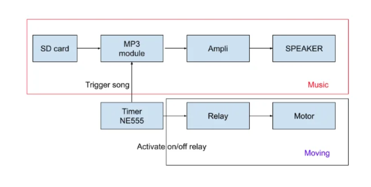
Two main electronic functions need to be realized:
a. Economical Timer: Based on the NE555 module, which is particularly interesting for fixed-time systems. It only requires two resistors and a capacitor to operate. We use the Timer555 in its astable mode (see diagram) more information on this device in this tutorial.
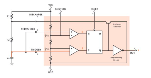
The choice of resistors and capacitor is based on the following formulas:
T = 0.693 *( R1 + R2) *C : Time High
T = 0.693 * R2 * C : Time Low
To simplify, you can use the following website to get direct values for a given pair (R1, R2, C1): link.
In our case, for a total operation of X minutes and Y minutes of movement, the resistances R1, R2, C1 are equal to ().
Premier test realise avec jumper et alim de labo :
b. Economical Sound System: Requires two new components: an MP3 module and an amplifier.
The MP3 module retrieves sound from an SD card and converts it into a signal that the speaker can understand. However, as the output signal is too weak, an amplifier is added to increase the sound signal’s power from the MP3.
The new system thus includes these components.
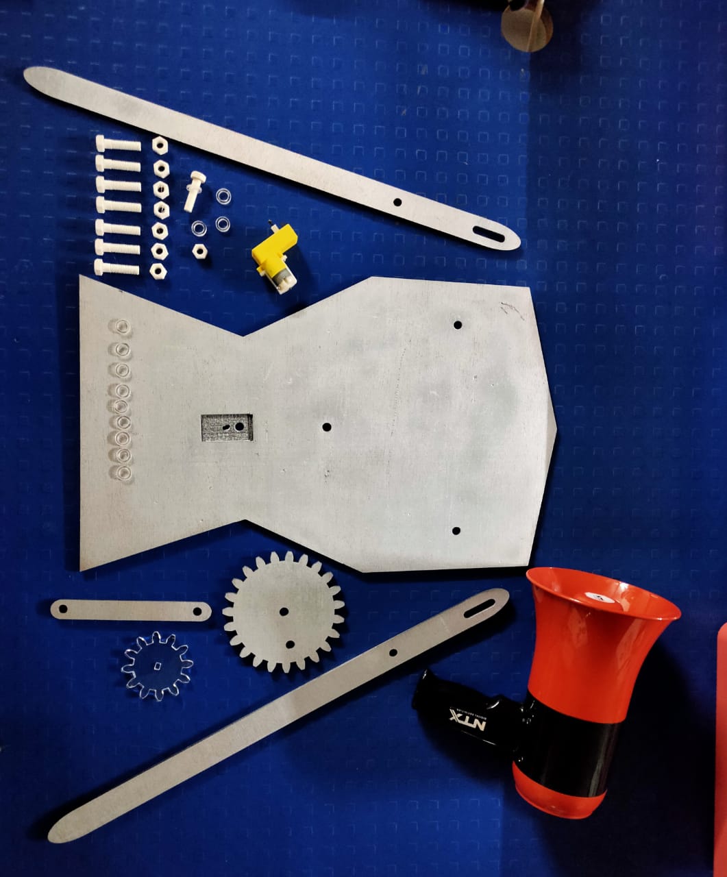
PART 1 Assembly of mechanism:
I have made all the parts ready by various D Fabrication procesS, and assembled it together.
PART 2 Creating a PCB:
Finally, we need to create a PCB that brings all these components together into a single module.
The PCB plans will be available here soon: [insert link when ready].